EP0936102A1 - Betätigungsvorrichtung, insbesondere für eine Verriegelungseinrichtung an einem Fahrzeugsitz - Google Patents
Betätigungsvorrichtung, insbesondere für eine Verriegelungseinrichtung an einem Fahrzeugsitz Download PDFInfo
- Publication number
- EP0936102A1 EP0936102A1 EP99101840A EP99101840A EP0936102A1 EP 0936102 A1 EP0936102 A1 EP 0936102A1 EP 99101840 A EP99101840 A EP 99101840A EP 99101840 A EP99101840 A EP 99101840A EP 0936102 A1 EP0936102 A1 EP 0936102A1
- Authority
- EP
- European Patent Office
- Prior art keywords
- slave
- locking
- actuating device
- piston
- cylinder
- Prior art date
- Legal status (The legal status is an assumption and is not a legal conclusion. Google has not performed a legal analysis and makes no representation as to the accuracy of the status listed.)
- Granted
Links
- 238000004519 manufacturing process Methods 0.000 description 4
- 239000012530 fluid Substances 0.000 description 3
- 238000009434 installation Methods 0.000 description 3
- 230000000694 effects Effects 0.000 description 2
- 210000003746 feather Anatomy 0.000 description 2
- 230000002411 adverse Effects 0.000 description 1
- 238000006073 displacement reaction Methods 0.000 description 1
- 230000002349 favourable effect Effects 0.000 description 1
- 238000009472 formulation Methods 0.000 description 1
- 239000007788 liquid Substances 0.000 description 1
- 239000012528 membrane Substances 0.000 description 1
- 238000000034 method Methods 0.000 description 1
- 239000000203 mixture Substances 0.000 description 1
- 230000002269 spontaneous effect Effects 0.000 description 1
- 230000001360 synchronised effect Effects 0.000 description 1
Images
Classifications
-
- F—MECHANICAL ENGINEERING; LIGHTING; HEATING; WEAPONS; BLASTING
- F15—FLUID-PRESSURE ACTUATORS; HYDRAULICS OR PNEUMATICS IN GENERAL
- F15B—SYSTEMS ACTING BY MEANS OF FLUIDS IN GENERAL; FLUID-PRESSURE ACTUATORS, e.g. SERVOMOTORS; DETAILS OF FLUID-PRESSURE SYSTEMS, NOT OTHERWISE PROVIDED FOR
- F15B7/00—Systems in which the movement produced is definitely related to the output of a volumetric pump; Telemotors
- F15B7/005—With rotary or crank input
-
- B—PERFORMING OPERATIONS; TRANSPORTING
- B60—VEHICLES IN GENERAL
- B60N—SEATS SPECIALLY ADAPTED FOR VEHICLES; VEHICLE PASSENGER ACCOMMODATION NOT OTHERWISE PROVIDED FOR
- B60N2/00—Seats specially adapted for vehicles; Arrangement or mounting of seats in vehicles
- B60N2/02—Seats specially adapted for vehicles; Arrangement or mounting of seats in vehicles the seat or part thereof being movable, e.g. adjustable
- B60N2/04—Seats specially adapted for vehicles; Arrangement or mounting of seats in vehicles the seat or part thereof being movable, e.g. adjustable the whole seat being movable
- B60N2/06—Seats specially adapted for vehicles; Arrangement or mounting of seats in vehicles the seat or part thereof being movable, e.g. adjustable the whole seat being movable slidable
- B60N2/07—Slide construction
- B60N2/0702—Slide construction characterised by its cross-section
- B60N2/072—Complex cross-section, e.g. obtained by extrusion
-
- B—PERFORMING OPERATIONS; TRANSPORTING
- B60—VEHICLES IN GENERAL
- B60N—SEATS SPECIALLY ADAPTED FOR VEHICLES; VEHICLE PASSENGER ACCOMMODATION NOT OTHERWISE PROVIDED FOR
- B60N2/00—Seats specially adapted for vehicles; Arrangement or mounting of seats in vehicles
- B60N2/02—Seats specially adapted for vehicles; Arrangement or mounting of seats in vehicles the seat or part thereof being movable, e.g. adjustable
- B60N2/04—Seats specially adapted for vehicles; Arrangement or mounting of seats in vehicles the seat or part thereof being movable, e.g. adjustable the whole seat being movable
- B60N2/06—Seats specially adapted for vehicles; Arrangement or mounting of seats in vehicles the seat or part thereof being movable, e.g. adjustable the whole seat being movable slidable
- B60N2/07—Slide construction
- B60N2/0735—Position and orientation of the slide as a whole
- B60N2/0747—Position and orientation of the slide as a whole the opening of the cross section being oriented in a direction different from the vertical, e.g. transversal
-
- B—PERFORMING OPERATIONS; TRANSPORTING
- B60—VEHICLES IN GENERAL
- B60N—SEATS SPECIALLY ADAPTED FOR VEHICLES; VEHICLE PASSENGER ACCOMMODATION NOT OTHERWISE PROVIDED FOR
- B60N2/00—Seats specially adapted for vehicles; Arrangement or mounting of seats in vehicles
- B60N2/02—Seats specially adapted for vehicles; Arrangement or mounting of seats in vehicles the seat or part thereof being movable, e.g. adjustable
- B60N2/04—Seats specially adapted for vehicles; Arrangement or mounting of seats in vehicles the seat or part thereof being movable, e.g. adjustable the whole seat being movable
- B60N2/06—Seats specially adapted for vehicles; Arrangement or mounting of seats in vehicles the seat or part thereof being movable, e.g. adjustable the whole seat being movable slidable
- B60N2/08—Seats specially adapted for vehicles; Arrangement or mounting of seats in vehicles the seat or part thereof being movable, e.g. adjustable the whole seat being movable slidable characterised by the locking device
- B60N2/0831—Movement of the latch
- B60N2/0862—Movement of the latch sliding
- B60N2/0868—Movement of the latch sliding in a transversal direction
-
- B—PERFORMING OPERATIONS; TRANSPORTING
- B60—VEHICLES IN GENERAL
- B60N—SEATS SPECIALLY ADAPTED FOR VEHICLES; VEHICLE PASSENGER ACCOMMODATION NOT OTHERWISE PROVIDED FOR
- B60N2/00—Seats specially adapted for vehicles; Arrangement or mounting of seats in vehicles
- B60N2/90—Details or parts not otherwise provided for
- B60N2/919—Positioning and locking mechanisms
- B60N2/929—Positioning and locking mechanisms linear
-
- F—MECHANICAL ENGINEERING; LIGHTING; HEATING; WEAPONS; BLASTING
- F15—FLUID-PRESSURE ACTUATORS; HYDRAULICS OR PNEUMATICS IN GENERAL
- F15B—SYSTEMS ACTING BY MEANS OF FLUIDS IN GENERAL; FLUID-PRESSURE ACTUATORS, e.g. SERVOMOTORS; DETAILS OF FLUID-PRESSURE SYSTEMS, NOT OTHERWISE PROVIDED FOR
- F15B7/00—Systems in which the movement produced is definitely related to the output of a volumetric pump; Telemotors
- F15B7/008—Systems in which the movement produced is definitely related to the output of a volumetric pump; Telemotors with rotary output
Definitions
- the invention relates to an actuating device, in particular for a locking device on a rail guide for longitudinal adjustment and locked bracket a vehicle seat opposite a vehicle floor, with a hydraulically acting transmitter part, with one on the Handle part acting and with a hydraulic Line connected to the transmitter part slave part.
- a pivotable vehicle seat described that can be used in an aircraft and comprises a bottom part and a back part, which together about an axis running across the seat under the bottom part are pivotable against each other.
- a hydraulic cylinder is provided to the parts in different Secure angular positions with respect to the axis.
- the back part can additionally over the same or another across the seat extending axis can be pivoted relative to the bottom part.
- the hydraulic cylinder can be swiveled on one fixed part, such as attached to a frame part of the seat. There is a double-acting inside the cylinder Piston that swivels over a rod with the bottom part connected is.
- Hydraulic lines run from each end of the Cylinder to a control valve, which is arranged in this way is that it can be comfortably operated by a passenger. By opening the control valve, the hydraulic fluid from one chamber of the cylinder to the other chamber overflow, the setting process taking place.
- a hydraulic control device is known from US Pat. No. 3,553,967 of the type described above, for which the control of a hydraulic as a specific application Locking an adjustable backrest Aircraft seat is specified.
- the known control device comprises a control unit and a working unit which connected to each other via a flexible hydraulic line are.
- a plunger in the control unit moves a movable one Wall that is filled with hydraulic fluid Chamber bounded, creating a corresponding movement brought about a movable wall of the work unit becomes.
- the control device itself is such designed so that it can be operated at the push of a button.
- the movable walls in the control and work unit are preferably designed as membranes.
- the invention has for its object an actuator to improve the type described at the beginning, that with high ease of use, low actuation force, space-saving installation option and unimpeded Spontaneous movement into an end position reduces effort is required for manufacture.
- This task is performed by an actuator solved the type described above, in which the transmitter part from a pressure-generating, single-acting, a master cylinder and an arrangement comprising a master piston and the slave part from a single-acting, at least one Slave cylinder and a slave piston arrangement there, the slave cylinder in particular pivotable is mounted and a piston rod of the slave piston articulated with a pivoted lever is that of an actuating arm on a locking element the locking device acts.
- the actuating device according to the invention stands out with high functionality and inexpensive installation options, especially in the seating area in the passenger compartment of a vehicle, through a simple structure and - connected with it - from low manufacturing costs.
- the mounting position for the actuator can be placed so that the positioning of the handle to initiate one hand force in the encoder part in an ergonomically very favorable position can take place.
- the relatively small Pressure leading into the hydraulic fluid Lines prevails, allows the use of weight-saving Plastic pipes. Leave the hydraulic lines is easy on and in the frame structure of a vehicle seat embarrassed. So it is possible, for example, the lines at least partially covered in the support tubes or To accommodate cavities in the seat structure.
- the actuating device according to the invention can be preferred on a locking device attached to a guide rail act, the locking openings and at least a locking element formed as a locking pin.
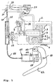
- FIG. 1 shows in schematic view of a positioning device Longitudinal adjustment and locked bracket in particular of a vehicle seat opposite a vehicle floor an actuating device according to the invention.
- the positioning device shown in Fig. 1 comprises at least one guide rail arranged parallel to the adjustment axis 1 and at least one locking device 2.
- the guide rail 1 consists of a support rail 3 firmly connected to the vehicle floor 4 lower part 5 and one with the vehicle seat, not shown movable relative to the lower part 5 parallel to the adjustment axis Upper part 6.
- the adjustment axis, not specified runs perpendicular to the plane of the drawing.
- Both parts 5, 6 of the guide rail 1 are for the purpose of Fixing the adjusted longitudinal position of the seat against each other lockable.
- the locking device 2 comprises in the illustrated embodiment in the lower part 5 and in the upper part 6 locking openings 7 and at least a corresponding locking element 8, the is designed as a locking pin.
- the locking element 8 is locked by means of a spring 9, one above the other arranged locking openings 7 of the lower part 5 and Upper part 6 held through position.
- a feather 9 can advantageously use a simple coil spring Find.
- the actuating device comprises a hydraulic acting encoder part, which consists of a pressure-generating, single-acting, a master cylinder 10 and one Arrangement piston 11 is formed.
- a handle 12 acts on the transmitter part.
- This handle 12 can - as shown - preferably designed as a hand lever be the one via a joint 13 with the master cylinder 10 and a further joint 14 with a piston rod 15 of the master piston 11 is connected. That way you can for generating pressure with the handle 12 pump movements be carried out.
- the actuating device one via a hydraulic line 16 with the transmitter part associated slave part associated.
- the handle 12 manual force is used in the hydraulic Transfer line 16 liquid to the slave part.
- the slave part consists of a single-acting, at least one slave cylinder 20 and one slave piston 21 comprehensive arrangement.
- the diameter of the slave cylinder 20 can preferably be smaller than the diameter of the master cylinder 10 be, so that from a certain, when operating the handle 12 covered path of the master piston 11 an enlarged Travel of the slave piston 21 or the associated Parts results.
- a lever pivotally mounted on a fixed joint 22 23 is via a further joint 24 with a piston rod 25 of the slave piston 21 connected.
- the slave cylinder 20 is in particular for cooperation with the lever 23 by means of a locking device 2 fixed pivot bearing 27 is pivotally mounted.
- By means of the Actuating arm 26 on the lever 23 can be the locking element 8 against the action of the spring 9 in its unlocked position be moved. If the unlocked position of the Locking element 8 can be repositioned, i.e. Longitudinal displacement, the vehicle seat into another desired position, in turn, a lock by means of the locking element 8.
- the Locking element 8 takes place under the effect of Immediately spring in its rest position.
- each locking parts 8 on two guide rails are assigned for a motor vehicle seat.
- the actuator described is for a variety can be used by locking devices, for example for free swivel devices on the backrests of Vehicle seats, for hood and trunk locks etc.
- the invention is not limited to that defined in claim 1 Characteristic combination limited, but can also through any other combination of certain Characteristics of all of the individual characteristics disclosed defined be. This means that basically practical each individual feature of claim 1 omitted or by at least one disclosed elsewhere in the application Single feature can be replaced. In this respect, the claim is 1 only as a first attempt at formulation for to understand an invention.
Landscapes
- Engineering & Computer Science (AREA)
- Mechanical Engineering (AREA)
- Aviation & Aerospace Engineering (AREA)
- Transportation (AREA)
- Physics & Mathematics (AREA)
- Fluid Mechanics (AREA)
- General Engineering & Computer Science (AREA)
- Seats For Vehicles (AREA)
- Lock And Its Accessories (AREA)
Abstract
Description
- 1
- Führungsschiene
- 2
- Verriegelungseinrichtung
- 3
- Tragschiene
- 4
- Fahrzeugboden
- 5
- Unterteil von 1
- 6
- Oberteil von 1
- 7
- Rastöffnungen
- 8
- Verriegelungselement
- 9
- Feder
- 10
- Geberzylinder
- 11
- Geberkolben
- 12
- Handhabe
- 13
- Gelenk an 10 und 12
- 14
- Gelenk an 15 und 12
- 15
- Kolbenstange an 11
- 16
- hydraulische Leitung
- 20
- Nehmerzylinder
- 21
- Nehmerkolben
- 22
- festes Gelenk an 23
- 23
- Hebel
- 24
- Gelenk an 23 und 25
- 25
- Kolbenstange an 21
- 26
- Stellarm an 23
- 27
- Gelenk an 20 und 2
Claims (7)
- Betätigungsvorrichtung, insbesondere für eine Verriegelungseinrishtung an einer Schienenführung zur Längsverstellung und verriegelten Halterung eines Fahrzeugsitzes gegenüber einem Fahrzeugboden, mit einem hydraulisch wirkenden Geberteil, mit einer auf das Geberteil wirkenden Handhabe und mit einem über eine hydraulische Leitung mit dem Geberteil verbundenen Nehmerteil,
dadurch gekennzeichnet, daß das Geberteil aus einer druckerzeugenden, einfachwirkenden, einen Geberzylinder (10) und einen Geberkolben (11) umfassenden Anordnung und das Nehmerteil aus einer einfachwirkenden, mindestens einen Nehmerzylinder (20) und einen Nehmerkolben (21) umfassenden Anordnung besteht, wobei der Nehmerzylinder (20) insbesondere verschwenkbar gelagert ist und eine Kolbenstange (25) des Nehmerkolbens (21) gelenkig mit einem verschwenkbar gelagerten Hebel (23) verbunden ist, der über einen Stellarm (26) auf ein Verriegelungselement (8) der Verriegelungseinrichtung (2) wirkt. - Betätigungseinrichtung nach Anspruch 1,
dadurch gekennzeichnet, daß der Durchmesser des Nehmerzylinders (20) kleiner als der Durchmesser des Geberzylinders (10) ist. - Betätigungseinrichtung nach Anspruch 1 oder 2,
dadurch gekennzeichnet, daß die Handhabe (12) als Handhebel ausgebildet ist, der über ein Gelenk (13) mit dem Geberzylinder (10) und über ein weiteres Gelenk (14) mit einer Kolbenstange (15) des Geberkolbens (11) verbunden ist. - Betätigungseinrichtung nach einem der Ansprüche 1 bis 3,
dadurch gekennzeichnet, daß die die Verriegelungseinrichtung (2) an mindestens einer parallel zur Verstellachse angeordneten Führungsschiene (1) angeordnet ist. - Betätigungseinrichtung nach Anspruch 4,
dadurch gekennzeichnet, daß die Führungsschiene (1) ein fest mit dem Fahrzeugboden (4) verbundenes Unterteil (5) und ein mit dem Fahrzeugsitz relativ zum Unterteil (5) parallel zur Verstellachse verschiebbares Oberteil (6) aufweist, wobei die Verriegelungseinrichtung (2) durch im Unterteil (5) und im Oberteil (6) befindliche Rastöffnungen (7) und das als Rastbolzen ausgebildete Verriegelungselement (8) gebildet ist. - Betätigungseinrichtung nach Anspruch 5,
dadurch gekennzeichnet, daß das Verriegelungselement (8) mittels einer Feder (9) in einer verrasteten, übereinander angeordnete Rastöffnungen (7) des Unterteiles (5) und Oberteiles (6) durchgreifenden Stellung gehalten und mittels des Stellarmes (26) gegen die Wirkung der Feder (9) in eine entrastete Stellung bewegbar ist. - Betätigungseinrichtung nach einem der Ansprüche 1 bis 6,
dadurch gekennzeichnet, daß das Nehmerteil aus einer zwei Nehmerzylinder (20) und zwei Nehmerkolben (21) umfassenden Anordnung besteht, die jeweils Verriegelungsteilen (8) an zwei Führungsschienen (1) zugeordnet sind.
Applications Claiming Priority (2)
| Application Number | Priority Date | Filing Date | Title |
|---|---|---|---|
| DE29802728U DE29802728U1 (de) | 1998-02-17 | 1998-02-17 | Betätigungsvorrichtung, insbesondere für eine Verriegelungseinrichtung an einem Fahrzeugsitz |
| DE29802728U | 1998-02-17 |
Publications (2)
| Publication Number | Publication Date |
|---|---|
| EP0936102A1 true EP0936102A1 (de) | 1999-08-18 |
| EP0936102B1 EP0936102B1 (de) | 2002-10-09 |
Family
ID=8052800
Family Applications (1)
| Application Number | Title | Priority Date | Filing Date |
|---|---|---|---|
| EP99101840A Expired - Lifetime EP0936102B1 (de) | 1998-02-17 | 1999-01-28 | Betätigungsvorrichtung, insbesondere für eine Verriegelungseinrichtung an einem Fahrzeugsitz |
Country Status (2)
| Country | Link |
|---|---|
| EP (1) | EP0936102B1 (de) |
| DE (2) | DE29802728U1 (de) |
Cited By (4)
| Publication number | Priority date | Publication date | Assignee | Title |
|---|---|---|---|---|
| DE10037839A1 (de) * | 2000-08-03 | 2002-02-21 | Keiper Gmbh & Co | Betätigungsvorrichtung für einen Fahrzeugsitz |
| WO2003013901A1 (de) * | 2001-08-11 | 2003-02-20 | Keiper Gmbh & Co | Verriegelungsvorrichtung für einen fahrzeugsitz |
| DE102013226148A1 (de) | 2013-01-15 | 2014-07-17 | Schaeffler Technologies Gmbh & Co. Kg | Hydraulische Türbetätigung mit einem Rollmembranzylinder |
| EP2829676A2 (de) | 2013-07-26 | 2015-01-28 | Schaeffler Technologies GmbH & Co. KG | Zwei oder mehrere, unabhängige, hydraulische Schlossbetätigungen |
Families Citing this family (2)
| Publication number | Priority date | Publication date | Assignee | Title |
|---|---|---|---|---|
| DE10110480C2 (de) * | 2001-03-05 | 2003-03-06 | Faurecia Autositze Gmbh & Co | Vorrichtung zur Fernbetätigung mindestens eines verstellbaren Kraftfahrzeugsitzbauteils |
| DE10341406B3 (de) * | 2003-09-05 | 2005-08-11 | Audi Ag | Betätigungseinrichtung für eine Verriegelungsvorrichtung an einem Fahrzeugsitz |
Citations (10)
| Publication number | Priority date | Publication date | Assignee | Title |
|---|---|---|---|---|
| US1398291A (en) * | 1918-08-02 | 1921-11-29 | Samuel F Arbuckle | Fluid-controlled actuating means |
| US3333418A (en) * | 1965-06-10 | 1967-08-01 | William E Harvey | Remote control device |
| US3553967A (en) | 1969-08-01 | 1971-01-12 | Porter Co P L | Hydraulic control assembly |
| GB1375990A (en) * | 1972-12-20 | 1974-12-04 | London Bankside Products Ltd | Hydraulic control systems |
| US4413214A (en) * | 1981-11-12 | 1983-11-01 | The Singer Company | Vented pneumatic foot controller |
| US4635999A (en) | 1982-10-28 | 1987-01-13 | Flight Equipment And Engineering Ltd. | Vehicle seats |
| DE3720936A1 (de) * | 1986-07-05 | 1988-01-07 | Volkswagen Ag | Geber- und/oder nehmereinheit fuer ein hydraulisches betaetigungssystem |
| FR2617916A1 (fr) * | 1987-07-06 | 1989-01-13 | Chardon Sa Louis | Dispositif de commande d'un verin a gaz ou hydro-pneumatique autobloquant |
| US5613733A (en) * | 1995-06-07 | 1997-03-25 | Ussc Group, Inc. | Device for the automatic operation of a seat release lever |
| DE19548246A1 (de) * | 1995-12-22 | 1997-06-26 | Behr Gmbh & Co | Vorrichtung zur leitungsgeführten Übertragung mechanischer Betätigungsbewegungen |
-
1998
- 1998-02-17 DE DE29802728U patent/DE29802728U1/de not_active Expired - Lifetime
-
1999
- 1999-01-28 EP EP99101840A patent/EP0936102B1/de not_active Expired - Lifetime
- 1999-01-28 DE DE59902989T patent/DE59902989D1/de not_active Expired - Fee Related
Patent Citations (10)
| Publication number | Priority date | Publication date | Assignee | Title |
|---|---|---|---|---|
| US1398291A (en) * | 1918-08-02 | 1921-11-29 | Samuel F Arbuckle | Fluid-controlled actuating means |
| US3333418A (en) * | 1965-06-10 | 1967-08-01 | William E Harvey | Remote control device |
| US3553967A (en) | 1969-08-01 | 1971-01-12 | Porter Co P L | Hydraulic control assembly |
| GB1375990A (en) * | 1972-12-20 | 1974-12-04 | London Bankside Products Ltd | Hydraulic control systems |
| US4413214A (en) * | 1981-11-12 | 1983-11-01 | The Singer Company | Vented pneumatic foot controller |
| US4635999A (en) | 1982-10-28 | 1987-01-13 | Flight Equipment And Engineering Ltd. | Vehicle seats |
| DE3720936A1 (de) * | 1986-07-05 | 1988-01-07 | Volkswagen Ag | Geber- und/oder nehmereinheit fuer ein hydraulisches betaetigungssystem |
| FR2617916A1 (fr) * | 1987-07-06 | 1989-01-13 | Chardon Sa Louis | Dispositif de commande d'un verin a gaz ou hydro-pneumatique autobloquant |
| US5613733A (en) * | 1995-06-07 | 1997-03-25 | Ussc Group, Inc. | Device for the automatic operation of a seat release lever |
| DE19548246A1 (de) * | 1995-12-22 | 1997-06-26 | Behr Gmbh & Co | Vorrichtung zur leitungsgeführten Übertragung mechanischer Betätigungsbewegungen |
Cited By (13)
| Publication number | Priority date | Publication date | Assignee | Title |
|---|---|---|---|---|
| DE10037839A1 (de) * | 2000-08-03 | 2002-02-21 | Keiper Gmbh & Co | Betätigungsvorrichtung für einen Fahrzeugsitz |
| DE10037839B4 (de) * | 2000-08-03 | 2004-09-30 | Keiper Gmbh & Co. Kg | Betätigungsvorrichtung für einen Fahrzeugsitz |
| WO2003013901A1 (de) * | 2001-08-11 | 2003-02-20 | Keiper Gmbh & Co | Verriegelungsvorrichtung für einen fahrzeugsitz |
| US6742753B2 (en) | 2001-08-11 | 2004-06-01 | Keiper Gmbh & Co. Kg | Locking device for a vehicle seat |
| WO2014111078A1 (de) | 2013-01-15 | 2014-07-24 | Schaeffler Technologies AG & Co. KG | Hydraulische türbetätigung mit einem rollmembranzylinder |
| DE102013226261A1 (de) | 2013-01-15 | 2014-07-17 | Schaeffler Technologies Gmbh & Co. Kg | Ziehender Rollmembranzylinder für ein Ausrück-/Betätigungssystem mit Wärmekompensation |
| DE102013226148A1 (de) | 2013-01-15 | 2014-07-17 | Schaeffler Technologies Gmbh & Co. Kg | Hydraulische Türbetätigung mit einem Rollmembranzylinder |
| WO2014111080A1 (de) | 2013-01-15 | 2014-07-24 | Schaeffler Technologies AG & Co. KG | Ziehender rollmembran-zylinder ohne zugankerkonstruktion mit innerem und äusserem rollbereich |
| WO2014111079A1 (de) | 2013-01-15 | 2014-07-24 | Schaeffler Technologies AG & Co. KG | Ziehender rollmembranzylinder für ein ausrück-/betätigungssystem mit wärmekompensation |
| DE102013226264A1 (de) | 2013-01-15 | 2014-07-31 | Schaeffler Technologies Gmbh & Co. Kg | Ziehender Rollmembran-Zylinder ohne Zugankerkonstruktion mit innerem und äußerem Rollbereich |
| EP2829676A2 (de) | 2013-07-26 | 2015-01-28 | Schaeffler Technologies GmbH & Co. KG | Zwei oder mehrere, unabhängige, hydraulische Schlossbetätigungen |
| DE102014214309A1 (de) | 2013-07-26 | 2015-01-29 | Schaeffler Technologies Gmbh & Co. Kg | Zwei oder mehrere unabhängige hydraulische Schlossbetätigungen |
| EP2829676A3 (de) * | 2013-07-26 | 2015-11-18 | Schaeffler Technologies AG & Co. KG | Zwei oder mehrere, unabhängige, hydraulische Schlossbetätigungen |
Also Published As
| Publication number | Publication date |
|---|---|
| DE59902989D1 (de) | 2002-11-14 |
| DE29802728U1 (de) | 1999-07-15 |
| EP0936102B1 (de) | 2002-10-09 |
Similar Documents
| Publication | Publication Date | Title |
|---|---|---|
| DE68916526T3 (de) | Fahrzeug-Türschlosssystem. | |
| EP0492006B1 (de) | Vorrichtung zum Niederholen des freien Endes eines Fahrzeugverdecks oder dergleichen | |
| DE2513302A1 (de) | Blockierbare, pneumatische oder hydropneumatische feder | |
| CH676417A5 (de) | ||
| EP3423301B1 (de) | Kopfstütze mit verbesserter verstelleinrichtung | |
| DE10218307A1 (de) | Verschlusssystem für ein Cabrioletverdeck | |
| EP2878230B1 (de) | Aufstellhebelmechanik mit Bowdenzug | |
| DE3202946C2 (de) | Fernbediente Türverriegelung für ein Vorder- und ein Hintertürschloß eines Kraftfahrzeugs | |
| EP3948013B1 (de) | Verstellbare sattelstützenanordnung | |
| EP0936102B1 (de) | Betätigungsvorrichtung, insbesondere für eine Verriegelungseinrichtung an einem Fahrzeugsitz | |
| DE102013217226B4 (de) | Fahrzeugsitz, insbesondere für eine hintere sitzreihe | |
| EP0991545B1 (de) | Kupplungseinrichtung für ein teleskopartig verstellbares Gebilde wie eine Kopftstütze o.dgl. | |
| DE830004C (de) | Hilfskraftbremseinrichtung, insbesondere fuer Kraftfahrzeuge | |
| DE4310454C1 (de) | Armlehne für Fahrzeugsitze | |
| DE4211493A1 (de) | Verriegelungsvorrichtung für ausziehbare Stützorgane | |
| EP4077843B1 (de) | Führungsanordnung zur führung wenigstens eines bewegbaren möbelteils | |
| DE3300993A1 (de) | Schwenkbare armlehne fuer kraftfahrzeugsitze | |
| DE102017100637A1 (de) | Stützstruktur für ein Sitzmöbel und Sitzmöbel | |
| EP1378410A2 (de) | Betätigungsvorrichtung für eine Feststellbremse | |
| DE69700727T2 (de) | Sitz mit veränderlicher Anordnung und erleichterter Bearbeitung für Kraftfahrzeuge | |
| DE202021104109U1 (de) | Elektromotorisch verstellbare Stützeinrichtung | |
| DE20021432U1 (de) | Medizinischer oder dentalmedizinischer Behandlungsstuhl mit einer einstellbaren Kopfstütze | |
| DE2721751B2 (de) | Doppelwandige Seitentür eines Kraftfahrzeugs mit einem absenkbaren Türfenster | |
| EP1161907A1 (de) | Vorrichtung zum Verstellen eines schwenkbaren Abschnitts an einem Sitz-oder Liegemöbel | |
| DE10016243A1 (de) | Betätigungsanordnung für ein Schloß, insbesondere ein Kraftfahrzeug-Türschloß, mit einem schwenkbar gelagerten Zuggriff |
Legal Events
| Date | Code | Title | Description |
|---|---|---|---|
| PUAI | Public reference made under article 153(3) epc to a published international application that has entered the european phase |
Free format text: ORIGINAL CODE: 0009012 |
|
| AK | Designated contracting states |
Kind code of ref document: A1 Designated state(s): DE FR GB IT |
|
| AX | Request for extension of the european patent |
Free format text: AL;LT;LV;MK;RO;SI |
|
| 17P | Request for examination filed |
Effective date: 19991215 |
|
| AKX | Designation fees paid |
Free format text: DE FR GB IT |
|
| GRAG | Despatch of communication of intention to grant |
Free format text: ORIGINAL CODE: EPIDOS AGRA |
|
| 17Q | First examination report despatched |
Effective date: 20011220 |
|
| GRAG | Despatch of communication of intention to grant |
Free format text: ORIGINAL CODE: EPIDOS AGRA |
|
| GRAG | Despatch of communication of intention to grant |
Free format text: ORIGINAL CODE: EPIDOS AGRA |
|
| GRAH | Despatch of communication of intention to grant a patent |
Free format text: ORIGINAL CODE: EPIDOS IGRA |
|
| GRAH | Despatch of communication of intention to grant a patent |
Free format text: ORIGINAL CODE: EPIDOS IGRA |
|
| GRAA | (expected) grant |
Free format text: ORIGINAL CODE: 0009210 |
|
| AK | Designated contracting states |
Kind code of ref document: B1 Designated state(s): DE FR GB IT |
|
| REG | Reference to a national code |
Ref country code: GB Ref legal event code: FG4D Free format text: NOT ENGLISH |
|
| REF | Corresponds to: |
Ref document number: 59902989 Country of ref document: DE Date of ref document: 20021114 |
|
| GBT | Gb: translation of ep patent filed (gb section 77(6)(a)/1977) |
Effective date: 20021128 |
|
| ET | Fr: translation filed | ||
| PLBE | No opposition filed within time limit |
Free format text: ORIGINAL CODE: 0009261 |
|
| STAA | Information on the status of an ep patent application or granted ep patent |
Free format text: STATUS: NO OPPOSITION FILED WITHIN TIME LIMIT |
|
| 26N | No opposition filed |
Effective date: 20030710 |
|
| PG25 | Lapsed in a contracting state [announced via postgrant information from national office to epo] |
Ref country code: IT Free format text: LAPSE BECAUSE OF NON-PAYMENT OF DUE FEES;WARNING: LAPSES OF ITALIAN PATENTS WITH EFFECTIVE DATE BEFORE 2007 MAY HAVE OCCURRED AT ANY TIME BEFORE 2007. THE CORRECT EFFECTIVE DATE MAY BE DIFFERENT FROM THE ONE RECORDED. Effective date: 20050128 |
|
| PGFP | Annual fee paid to national office [announced via postgrant information from national office to epo] |
Ref country code: FR Payment date: 20051208 Year of fee payment: 8 |
|
| PGFP | Annual fee paid to national office [announced via postgrant information from national office to epo] |
Ref country code: GB Payment date: 20051213 Year of fee payment: 8 |
|
| PGFP | Annual fee paid to national office [announced via postgrant information from national office to epo] |
Ref country code: DE Payment date: 20060131 Year of fee payment: 8 |
|
| PG25 | Lapsed in a contracting state [announced via postgrant information from national office to epo] |
Ref country code: DE Free format text: LAPSE BECAUSE OF NON-PAYMENT OF DUE FEES Effective date: 20070801 |
|
| GBPC | Gb: european patent ceased through non-payment of renewal fee |
Effective date: 20070128 |
|
| REG | Reference to a national code |
Ref country code: FR Ref legal event code: ST Effective date: 20070930 |
|
| PG25 | Lapsed in a contracting state [announced via postgrant information from national office to epo] |
Ref country code: GB Free format text: LAPSE BECAUSE OF NON-PAYMENT OF DUE FEES Effective date: 20070128 |
|
| PG25 | Lapsed in a contracting state [announced via postgrant information from national office to epo] |
Ref country code: FR Free format text: LAPSE BECAUSE OF NON-PAYMENT OF DUE FEES Effective date: 20070131 |