EP0933482A2 - Elément préfabriqué pour dalle de balcon en porte-à-faux - Google Patents
Elément préfabriqué pour dalle de balcon en porte-à-faux Download PDFInfo
- Publication number
- EP0933482A2 EP0933482A2 EP98122818A EP98122818A EP0933482A2 EP 0933482 A2 EP0933482 A2 EP 0933482A2 EP 98122818 A EP98122818 A EP 98122818A EP 98122818 A EP98122818 A EP 98122818A EP 0933482 A2 EP0933482 A2 EP 0933482A2
- Authority
- EP
- European Patent Office
- Prior art keywords
- insulating body
- prefabricated component
- component according
- prefabricated
- cuboid
- Prior art date
- Legal status (The legal status is an assumption and is not a legal conclusion. Google has not performed a legal analysis and makes no representation as to the accuracy of the status listed.)
- Granted
Links
Images


Classifications
-
- E—FIXED CONSTRUCTIONS
- E04—BUILDING
- E04B—GENERAL BUILDING CONSTRUCTIONS; WALLS, e.g. PARTITIONS; ROOFS; FLOORS; CEILINGS; INSULATION OR OTHER PROTECTION OF BUILDINGS
- E04B1/00—Constructions in general; Structures which are not restricted either to walls, e.g. partitions, or floors or ceilings or roofs
- E04B1/003—Balconies; Decks
- E04B1/0038—Anchoring devices specially adapted therefor with means for preventing cold bridging
Definitions
- the invention relates to a prefabricated component for a cantilever Balcony slab according to the preamble of the main claim.
- Prefabricated components for the formation of balcony slabs have the task not only the required load-bearing capacity for the balcony slab create, but must also be connected to the main structure be that on the one hand a power transmission in the Main structure when the balcony slab is loaded, on the other hand heat transfer is prevented as possible, so that in winter such balcony slabs no cold bridges for that Represent main structure.
- a prefabricated component is described in DE 94 17 777 U1.
- an insulating body on the edge of a Filigree collar plate arranged and those provided in the insulating body Reinforcing bars are in the filigree cantilever cast in a prefab plant.
- pressure plates provided that connected with pressure link rebar are.
- connection means that on the one hand connect to the reinforcement of the main structure, on the other hand the connection to the reinforcement of the balcony slab enable precast component, but with from Concrete existing thrust bearings in the lower area, d. H. so at the level of the precast panels to the main structure.
- the use of such thrust bearings made of concrete is much cheaper than a connection via metal components, especially compared to stainless steel, which has a high thermal conductivity having. It was found that when in the Insulating bodies, for example, every 17 cm through openings of a size 5 x 5 cm, d. H.
- the present invention is based on the object To improve the manufacture of the generic prefabricated component, by enabling the highest possible series production becomes.
- the actual insulation body with regard to its lower area is always manufactured consistently in series production and that a prefabricated cuboid is used, which in different Strengths of the material mixture in an economical Series production can be made.
- the mix of materials can be used as high strength concrete, as fiberglass concrete, as Steel fiber reinforced concrete or plastic fiber reinforced concrete be. According to a particular proposal of the invention plastic can also be used here.
- the cuboid preferably has one greater length than the width of the insulation body, so that it protrudes outwards over the insulation body and is here with Anchoring means equipped that a good integration in enable the in-situ concrete mass to be applied to the precast slab.
- the lower area of the insulation body is the insulation body has completely traversing recess and the thrust bearing through one inserted or filled into the recess Material mixture with low thermal conductivity and high Compressive strength is formed.
- the thrust bearings are not above the Insulating body towards the building and are not with firmly connected to the building, so that no unwanted ones Tensions can occur.
- the insulating body can be divided into individual elements, so that easier handling or adaptation to different large precast panels is possible.
- the transverse force supports can be dovetail-shaped Precast elements to be formed, which in the precast production facility with the precast slab and the Insulation bodies are connected.
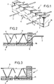
- insulating body 1 which is made of an insulating material exists that is poorly heat conductive.
- the Insulating bodies 1 are incorporated in the upper area of tension rods 2 and in the central area, shear bars 3, the shear bars 3, as clearly shown in FIGS. 2 and 3, the Cross the insulation body at an angle.
- Both the tie rods 2 as the transverse force bars 3 are preferably made of stainless steel, which is less thermally conductive than normal steel is, preferably so-called V4A steel.
- recesses 4 can be seen, which are used to form thrust bearings 5, the recesses having a size of 10-70 cm 2 , for example 5 ⁇ 5 cm, being at a distance of 17 cm, while the entire insulating body has a length of 1.05 m.
- the recesses 4 of the insulating body 1 below close.
- the underside of the insulating body 1 can, for example covered by a continuous adhesive strip be. This holds the bottom of the insulating body 1 over the length seen together and prevents the Move the insulation body 1 apart at the bottom like a fan can bend. Furthermore, damage to the webs avoided between the recesses 4.
- the tape which can consist of plastic, metal or the like, can later be removed to allow a visual inspection of the thrust bearing 5.
- others can Cover materials may be provided, possibly even non-removable Covering materials:
- the recesses 4 do not necessarily have to open on the lower edge of the insulation body.
- the sliding layer 26 can have a thickness of 0.5 to 1 mm and corresponds in height to the height of Thrust bearing 5 and can either over the entire length of the Insulating body 1 run or only in the area of the thrust bearing 5 to be ordered.
- the insulating body 1 has a width of 8 cm and a Can have a height of 20 cm.
- the insulating body 1 is in the illustrated embodiment constructed in two parts: the z. B. oblique dividing line between the upper part and the lower part of the insulating body 1 runs in the inclined plane along which the shear bars 3 run with its sloping middle section. In this way, the shear bars 3 in a simple manner be placed on the lower part of the insulating body 1, so that a quick assembly with little expenditure of time is supported becomes.
- Tension rods 2 can be through slots in the upper part of the Insulating body 1 are provided, inserted in this upper part are, so that a very quick assembly is also supported here becomes. As an alternative to such slots, provision can be made only perforations in the upper part of the insulating body 1 to provide.
- the generic state of the art proposes that 3 shear supports are provided instead of the shear bars become.
- This shear force supports are achieved in that the insulating body seen from above in the form of a dovetail Recesses are provided in the one in the precast production facility applied concrete can flow.
- a shear support 25 is provided as a finished part made of a material mixture is produced and inserted into the insulating body and then in the precast production facility during casting the precast slab is integrated.
- too last lattice bar to be covered with expanded metal the exclusion of the local concrete to the free end of the precast slab 6 shields.
- the transverse force 25 can be applied with a sliding layer 26 be provided.
- a prefabricated plate 6 can be seen, of which the lattice girder 11 and the connecting rod 9 connecting them can be seen.
- the procedure is such that previously a concrete mix in the area of the recesses 4 is used to form a thrust bearing 5, the high Compressive strength, but has a low thermal conductivity possesses, these properties through appropriate additives can be achieved.
- the finished cast prefabricated plate 6 thus engages with a thrust bearing 5 in the recesses 4, so that that shown in Fig. 2 Finished part is created in a finished part production facility, which are now attached to the building on the spot can. Then the space recognizable from FIG In-situ concrete backfilled, creating a connection between the building side In-situ concrete and the in-situ concrete of the balcony slab created is and whereby the shear force wire 3 on all sides of Concrete is surrounded. It is therefore protected against corrosion, so that it does not have to be made of stainless steel.
- cuboids 20 are in the in the insulating body 1 provided recesses 4 cuboids 20 inserted, which are prefabricated and therefore in the adapted different Strengths can be created. These cuboids exist z. B. made of concrete, preferably high strength Concrete, but it can also be fiberglass, steel fiber or Plastic fiber concrete can be used. The use of Plastic is possible. As can be clearly seen from FIG. 3, the cuboid 20 has a greater length than the width of the Insulating body 1 and is thus on the precast panel 6th facing side over the front edge of the insulating body 1 about.
- the cuboid 20 can be made of the same material have provided anchoring teeth 23 and in the Cuboid can be used a demolition reinforcement 22, which that the cuboid 20 is prefabricated, exactly in the middle of the Cuboid is installed and used and with the reinforcement the precast plate 6 can be connected.
- the insulating body 1 at its top slots 12 in which the tension rods 2 are inserted can be, while continuing in this insulation body 1 also not shown transverse force rods can be incorporated can.
- the insulating body 1 essentially has on its underside A recess extends over its entire length 13, which is either rectangular in section or but can also be designed so that the top of the recess 13 tilts from one side to the other so that a recess 13 is achieved, which is two right angles on average and has two angles, one larger and one is less than 90 °.
- the section line 14 it is indicated that the insulating body 1 as well as the insulating body according to FIG. 1 can also be formed in two parts, this cutting line does not have to run obliquely.
Landscapes
- Engineering & Computer Science (AREA)
- Architecture (AREA)
- Physics & Mathematics (AREA)
- Electromagnetism (AREA)
- Civil Engineering (AREA)
- Structural Engineering (AREA)
- Steps, Ramps, And Handrails (AREA)
- Building Environments (AREA)
- Forms Removed On Construction Sites Or Auxiliary Members Thereof (AREA)
- Buildings Adapted To Withstand Abnormal External Influences (AREA)
- Floor Finish (AREA)
Applications Claiming Priority (2)
| Application Number | Priority Date | Filing Date | Title |
|---|---|---|---|
| DE29801308U | 1998-01-28 | ||
| DE29801308U DE29801308U1 (de) | 1998-01-28 | 1998-01-28 | Fertigbauteil für eine auskragende Balkonplatte |
Publications (3)
| Publication Number | Publication Date |
|---|---|
| EP0933482A2 true EP0933482A2 (fr) | 1999-08-04 |
| EP0933482A3 EP0933482A3 (fr) | 2000-05-10 |
| EP0933482B1 EP0933482B1 (fr) | 2004-05-12 |
Family
ID=8051784
Family Applications (1)
| Application Number | Title | Priority Date | Filing Date |
|---|---|---|---|
| EP98122818A Expired - Lifetime EP0933482B1 (fr) | 1998-01-28 | 1998-12-01 | Elément préfabriqué pour dalle de balcon en porte-à-faux |
Country Status (3)
| Country | Link |
|---|---|
| EP (1) | EP0933482B1 (fr) |
| AT (1) | ATE266778T1 (fr) |
| DE (2) | DE29801308U1 (fr) |
Cited By (4)
| Publication number | Priority date | Publication date | Assignee | Title |
|---|---|---|---|---|
| EP1669501A1 (fr) * | 2001-01-23 | 2006-06-14 | Schöck Bauteile GmbH | Elément de construction pour l'isolation thermique |
| FR2887905A1 (fr) * | 2005-06-30 | 2007-01-05 | Lafarge Sa | Rupteur thermique |
| EP2138641A2 (fr) * | 2008-06-24 | 2009-12-30 | SCHÖCK BAUTEILE GmbH | Elément de construction destiné à l'isolation thermique et matériau d'isolation pour le domaine de la construction |
| EP3800302A1 (fr) | 2019-10-02 | 2021-04-07 | Sonntag, Susanne | Corps isolant destiné à l'isolation thermique entre un bâtiment et une partie externe en saillie ainsi que bâtiment doté d'une partie externe en saillie et d'au moins un corps isolant disposé entre eux |
Families Citing this family (3)
| Publication number | Priority date | Publication date | Assignee | Title |
|---|---|---|---|---|
| DE29801308U1 (de) * | 1998-01-28 | 1998-04-30 | Syspro Gruppe Betonbauteile E | Fertigbauteil für eine auskragende Balkonplatte |
| DE102006044958A1 (de) * | 2006-09-22 | 2008-04-03 | Kki Enterprises Gmbh | Fertigbauteil für eine auskragende Balkonplatte |
| DE102011056170A1 (de) * | 2011-12-08 | 2013-06-13 | JUWÖ POROTON-Werke Ernst Jungk & Sohn GmbH | Mauerstein |
Citations (3)
| Publication number | Priority date | Publication date | Assignee | Title |
|---|---|---|---|---|
| DE9417777U1 (de) | 1994-11-05 | 1995-01-05 | Dausend Hans Werner | Kragplattenanschlußelement |
| DE9420560U1 (de) | 1994-10-31 | 1995-03-30 | Hako Bautechnik Ges M B H | Wärmedämmendes Anschlußstück |
| DE19652165A1 (de) | 1996-12-05 | 1998-06-18 | Syspro Gruppe Betonbauteile E | Fertigbauteil für eine auskragende Balkonplatte |
Family Cites Families (4)
| Publication number | Priority date | Publication date | Assignee | Title |
|---|---|---|---|---|
| DE3302719C1 (de) * | 1983-01-27 | 1984-08-23 | Eberhard Ing. Schöck (grad.), 7570 Baden-Baden | Bauelement zur Waermedaemmung bei Gebaeuden |
| DE3426538A1 (de) * | 1984-07-18 | 1986-01-23 | Schöck, Eberhard, Ing.(grad.), 7570 Baden-Baden | Bauelement zur waermedaemmung bei gebaeuden |
| DE9410288U1 (de) * | 1993-12-22 | 1994-10-13 | Frank Gmbh & Co Kg Max | Balkonanschluß |
| DE29801308U1 (de) * | 1998-01-28 | 1998-04-30 | Syspro Gruppe Betonbauteile E | Fertigbauteil für eine auskragende Balkonplatte |
-
1998
- 1998-01-28 DE DE29801308U patent/DE29801308U1/de not_active Expired - Lifetime
- 1998-12-01 DE DE59811382T patent/DE59811382D1/de not_active Expired - Lifetime
- 1998-12-01 AT AT98122818T patent/ATE266778T1/de not_active IP Right Cessation
- 1998-12-01 EP EP98122818A patent/EP0933482B1/fr not_active Expired - Lifetime
Patent Citations (3)
| Publication number | Priority date | Publication date | Assignee | Title |
|---|---|---|---|---|
| DE9420560U1 (de) | 1994-10-31 | 1995-03-30 | Hako Bautechnik Ges M B H | Wärmedämmendes Anschlußstück |
| DE9417777U1 (de) | 1994-11-05 | 1995-01-05 | Dausend Hans Werner | Kragplattenanschlußelement |
| DE19652165A1 (de) | 1996-12-05 | 1998-06-18 | Syspro Gruppe Betonbauteile E | Fertigbauteil für eine auskragende Balkonplatte |
Cited By (7)
| Publication number | Priority date | Publication date | Assignee | Title |
|---|---|---|---|---|
| EP1669501A1 (fr) * | 2001-01-23 | 2006-06-14 | Schöck Bauteile GmbH | Elément de construction pour l'isolation thermique |
| EP1225283B2 (fr) † | 2001-01-23 | 2014-10-29 | SCHÖCK BAUTEILE GmbH | Elément de construction pour l'isolation thermique |
| FR2887905A1 (fr) * | 2005-06-30 | 2007-01-05 | Lafarge Sa | Rupteur thermique |
| WO2007003739A1 (fr) * | 2005-06-30 | 2007-01-11 | Lafarge | Rupteur thermique |
| US8151531B2 (en) | 2005-06-30 | 2012-04-10 | Lafarge | Thermal barrier |
| EP2138641A2 (fr) * | 2008-06-24 | 2009-12-30 | SCHÖCK BAUTEILE GmbH | Elément de construction destiné à l'isolation thermique et matériau d'isolation pour le domaine de la construction |
| EP3800302A1 (fr) | 2019-10-02 | 2021-04-07 | Sonntag, Susanne | Corps isolant destiné à l'isolation thermique entre un bâtiment et une partie externe en saillie ainsi que bâtiment doté d'une partie externe en saillie et d'au moins un corps isolant disposé entre eux |
Also Published As
| Publication number | Publication date |
|---|---|
| ATE266778T1 (de) | 2004-05-15 |
| DE59811382D1 (de) | 2004-06-17 |
| DE29801308U1 (de) | 1998-04-30 |
| EP0933482A3 (fr) | 2000-05-10 |
| EP0933482B1 (fr) | 2004-05-12 |
Similar Documents
| Publication | Publication Date | Title |
|---|---|---|
| AT396274B (de) | Bewehrungskoerper fuer eine deckenplatte | |
| DE19652165C2 (de) | Fertigbauteil für eine auskragende Balkonplatte | |
| EP0318010B1 (fr) | Elément de liaison pour plaque en béton en porte-à-faux | |
| DE3422905A1 (de) | Vorrichtung zum verbinden einer balkonplatte und einer geschossdecke | |
| AT396151B (de) | Anschlusselement fuer kragplatten sowie aus mehreren anschlusselementen zusammengesetztes anschlusselement | |
| DE19711813C2 (de) | Thermisch isolierendes Bauelement | |
| EP0933482B1 (fr) | Elément préfabriqué pour dalle de balcon en porte-à-faux | |
| DE3328070C2 (fr) | ||
| DE3426538C2 (fr) | ||
| EP2209952B1 (fr) | Élément d'écartement et composant pour la production d'une structure murale, et procédé et dispositif correspondants | |
| DE875403C (de) | Bauelement und Verfahren zu seiner Herstellung | |
| EP3118382A1 (fr) | Élement de construction destine a l'isolation thermique | |
| EP0745733A1 (fr) | Elément de dalle en porte-à-faux et/ou élément de joint pour ouvrages de construction armés | |
| EP0796961B1 (fr) | Bétoncellulaire avec système d'armatures | |
| DE102020114611B3 (de) | Schalungsanordnung | |
| EP2175079B1 (fr) | Procédé de formation d'une armature d'angle résistante à la flexion pour la construction en béton armé, élément d'armature et armature d'angle résistante à la flexion | |
| AT390099B (de) | Die verwendung einer fuer bauteile aus stahlbeton bestimmten bewehrung | |
| AT395195B (de) | Deckenartige anordnung aus miteinander verbundenen dielen, insbesondere solchen aus beton | |
| DE1229270B (de) | Stahlbetonrippendecke | |
| AT392665B (de) | Ueberlage | |
| DE19829401A1 (de) | Bauelement | |
| AT408362B (de) | Abstandhalter für gitterträger | |
| EP4123097A1 (fr) | Panier de raccordement | |
| AT404957B (de) | Bewehrungselement | |
| DE19816279A1 (de) | Deckenplatte |
Legal Events
| Date | Code | Title | Description |
|---|---|---|---|
| PUAI | Public reference made under article 153(3) epc to a published international application that has entered the european phase |
Free format text: ORIGINAL CODE: 0009012 |
|
| AK | Designated contracting states |
Kind code of ref document: A2 Designated state(s): AT CH DE LI |
|
| AX | Request for extension of the european patent |
Free format text: AL;LT;LV;MK;RO;SI |
|
| RAP1 | Party data changed (applicant data changed or rights of an application transferred) |
Owner name: KAHMER, HERBERT H., DR. Owner name: ORTH, WILHELM, DIPL.-ING. |
|
| PUAL | Search report despatched |
Free format text: ORIGINAL CODE: 0009013 |
|
| AK | Designated contracting states |
Kind code of ref document: A3 Designated state(s): AT BE CH CY DE DK ES FI FR GB GR IE IT LI LU MC NL PT SE |
|
| AX | Request for extension of the european patent |
Free format text: AL;LT;LV;MK;RO;SI |
|
| 17P | Request for examination filed |
Effective date: 20001028 |
|
| AKX | Designation fees paid |
Free format text: AT CH DE LI |
|
| 17Q | First examination report despatched |
Effective date: 20030214 |
|
| GRAP | Despatch of communication of intention to grant a patent |
Free format text: ORIGINAL CODE: EPIDOSNIGR1 |
|
| GRAS | Grant fee paid |
Free format text: ORIGINAL CODE: EPIDOSNIGR3 |
|
| GRAA | (expected) grant |
Free format text: ORIGINAL CODE: 0009210 |
|
| AK | Designated contracting states |
Kind code of ref document: B1 Designated state(s): AT CH DE LI |
|
| REG | Reference to a national code |
Ref country code: CH Ref legal event code: EP |
|
| REF | Corresponds to: |
Ref document number: 59811382 Country of ref document: DE Date of ref document: 20040617 Kind code of ref document: P |
|
| PG25 | Lapsed in a contracting state [announced via postgrant information from national office to epo] |
Ref country code: AT Free format text: LAPSE BECAUSE OF NON-PAYMENT OF DUE FEES Effective date: 20041201 |
|
| PLBE | No opposition filed within time limit |
Free format text: ORIGINAL CODE: 0009261 |
|
| STAA | Information on the status of an ep patent application or granted ep patent |
Free format text: STATUS: NO OPPOSITION FILED WITHIN TIME LIMIT |
|
| 26N | No opposition filed |
Effective date: 20050215 |
|
| REG | Reference to a national code |
Ref country code: CH Ref legal event code: PL |
|
| REG | Reference to a national code |
Ref country code: CH Ref legal event code: AEN Free format text: DAS PATENT IST AUFGRUND DES WEITERBEHANDLUNGSANTRAGS VOM 16.08.2005 REAKTIVIERT WORDEN. |
|
| REG | Reference to a national code |
Ref country code: CH Ref legal event code: NV Representative=s name: BRAUNPAT BRAUN EDER AG |
|
| PG25 | Lapsed in a contracting state [announced via postgrant information from national office to epo] |
Ref country code: LI Free format text: LAPSE BECAUSE OF NON-PAYMENT OF DUE FEES Effective date: 20051231 Ref country code: CH Free format text: LAPSE BECAUSE OF NON-PAYMENT OF DUE FEES Effective date: 20051231 |
|
| REG | Reference to a national code |
Ref country code: CH Ref legal event code: PL |
|
| REG | Reference to a national code |
Ref country code: CH Ref legal event code: AEN Free format text: DAS PATENT IST AUFGRUND DES WEITERBEHANDLUNGSANTRAGS VOM 09.08.2006 REAKTIVIERT WORDEN. |
|
| REG | Reference to a national code |
Ref country code: CH Ref legal event code: PUE Owner name: KKI ENTERPRISES GMBH, CH Free format text: FORMER OWNER: ORTH, WILHELM, DIPL.-ING., DE |
|
| REG | Reference to a national code |
Ref country code: DE Ref legal event code: R082 Ref document number: 59811382 Country of ref document: DE Representative=s name: PATENTANWAELTE BERNHARDT/WOLFF PARTNERSCHAFT M, DE Ref country code: DE Ref legal event code: R082 Ref document number: 59811382 Country of ref document: DE Representative=s name: PATENTANWAELTE BERNHARDT/WOLFF PARTNERSCHAFT, DE |
|
| PGFP | Annual fee paid to national office [announced via postgrant information from national office to epo] |
Ref country code: DE Payment date: 20160407 Year of fee payment: 18 |
|
| REG | Reference to a national code |
Ref country code: DE Ref legal event code: R119 Ref document number: 59811382 Country of ref document: DE |
|
| PGFP | Annual fee paid to national office [announced via postgrant information from national office to epo] |
Ref country code: CH Payment date: 20170510 Year of fee payment: 19 |
|
| PG25 | Lapsed in a contracting state [announced via postgrant information from national office to epo] |
Ref country code: DE Free format text: LAPSE BECAUSE OF NON-PAYMENT OF DUE FEES Effective date: 20170701 |
|
| REG | Reference to a national code |
Ref country code: CH Ref legal event code: PL |
|
| PG25 | Lapsed in a contracting state [announced via postgrant information from national office to epo] |
Ref country code: CH Free format text: LAPSE BECAUSE OF NON-PAYMENT OF DUE FEES Effective date: 20171231 Ref country code: LI Free format text: LAPSE BECAUSE OF NON-PAYMENT OF DUE FEES Effective date: 20171231 |
|
| RIC2 | Information provided on ipc code assigned after grant |
Ipc: E04B 1/00 20060101AFI19990430BHEP Ipc: E04B 1/76 20060101ALI19990430BHEP |