EP0931991A2 - Système frigorifique supercritique - Google Patents
Système frigorifique supercritique Download PDFInfo
- Publication number
- EP0931991A2 EP0931991A2 EP99101023A EP99101023A EP0931991A2 EP 0931991 A2 EP0931991 A2 EP 0931991A2 EP 99101023 A EP99101023 A EP 99101023A EP 99101023 A EP99101023 A EP 99101023A EP 0931991 A2 EP0931991 A2 EP 0931991A2
- Authority
- EP
- European Patent Office
- Prior art keywords
- pressure
- refrigerant
- valve
- compressor
- radiator
- Prior art date
- Legal status (The legal status is an assumption and is not a legal conclusion. Google has not performed a legal analysis and makes no representation as to the accuracy of the status listed.)
- Withdrawn
Links
Images


Classifications
-
- B—PERFORMING OPERATIONS; TRANSPORTING
- B60—VEHICLES IN GENERAL
- B60H—ARRANGEMENTS OF HEATING, COOLING, VENTILATING OR OTHER AIR-TREATING DEVICES SPECIALLY ADAPTED FOR PASSENGER OR GOODS SPACES OF VEHICLES
- B60H1/00—Heating, cooling or ventilating devices
- B60H1/32—Cooling devices
- B60H1/3204—Cooling devices using compression
- B60H1/3225—Cooling devices using compression characterised by safety arrangements, e.g. compressor anti-seizure means or by signalling devices
-
- F—MECHANICAL ENGINEERING; LIGHTING; HEATING; WEAPONS; BLASTING
- F25—REFRIGERATION OR COOLING; COMBINED HEATING AND REFRIGERATION SYSTEMS; HEAT PUMP SYSTEMS; MANUFACTURE OR STORAGE OF ICE; LIQUEFACTION SOLIDIFICATION OF GASES
- F25B—REFRIGERATION MACHINES, PLANTS OR SYSTEMS; COMBINED HEATING AND REFRIGERATION SYSTEMS; HEAT PUMP SYSTEMS
- F25B41/00—Fluid-circulation arrangements
- F25B41/30—Expansion means; Dispositions thereof
- F25B41/31—Expansion valves
- F25B41/33—Expansion valves with the valve member being actuated by the fluid pressure, e.g. by the pressure of the refrigerant
- F25B41/335—Expansion valves with the valve member being actuated by the fluid pressure, e.g. by the pressure of the refrigerant via diaphragms
-
- F—MECHANICAL ENGINEERING; LIGHTING; HEATING; WEAPONS; BLASTING
- F25—REFRIGERATION OR COOLING; COMBINED HEATING AND REFRIGERATION SYSTEMS; HEAT PUMP SYSTEMS; MANUFACTURE OR STORAGE OF ICE; LIQUEFACTION SOLIDIFICATION OF GASES
- F25B—REFRIGERATION MACHINES, PLANTS OR SYSTEMS; COMBINED HEATING AND REFRIGERATION SYSTEMS; HEAT PUMP SYSTEMS
- F25B41/00—Fluid-circulation arrangements
- F25B41/30—Expansion means; Dispositions thereof
- F25B41/31—Expansion valves
- F25B41/34—Expansion valves with the valve member being actuated by electric means, e.g. by piezoelectric actuators
- F25B41/35—Expansion valves with the valve member being actuated by electric means, e.g. by piezoelectric actuators by rotary motors, e.g. by stepping motors
-
- F—MECHANICAL ENGINEERING; LIGHTING; HEATING; WEAPONS; BLASTING
- F25—REFRIGERATION OR COOLING; COMBINED HEATING AND REFRIGERATION SYSTEMS; HEAT PUMP SYSTEMS; MANUFACTURE OR STORAGE OF ICE; LIQUEFACTION SOLIDIFICATION OF GASES
- F25B—REFRIGERATION MACHINES, PLANTS OR SYSTEMS; COMBINED HEATING AND REFRIGERATION SYSTEMS; HEAT PUMP SYSTEMS
- F25B9/00—Compression machines, plants or systems, in which the refrigerant is air or other gas of low boiling point
- F25B9/002—Compression machines, plants or systems, in which the refrigerant is air or other gas of low boiling point characterised by the refrigerant
- F25B9/008—Compression machines, plants or systems, in which the refrigerant is air or other gas of low boiling point characterised by the refrigerant the refrigerant being carbon dioxide
-
- F—MECHANICAL ENGINEERING; LIGHTING; HEATING; WEAPONS; BLASTING
- F25—REFRIGERATION OR COOLING; COMBINED HEATING AND REFRIGERATION SYSTEMS; HEAT PUMP SYSTEMS; MANUFACTURE OR STORAGE OF ICE; LIQUEFACTION SOLIDIFICATION OF GASES
- F25B—REFRIGERATION MACHINES, PLANTS OR SYSTEMS; COMBINED HEATING AND REFRIGERATION SYSTEMS; HEAT PUMP SYSTEMS
- F25B2309/00—Gas cycle refrigeration machines
- F25B2309/06—Compression machines, plants or systems characterised by the refrigerant being carbon dioxide
- F25B2309/061—Compression machines, plants or systems characterised by the refrigerant being carbon dioxide with cycle highest pressure above the supercritical pressure
-
- F—MECHANICAL ENGINEERING; LIGHTING; HEATING; WEAPONS; BLASTING
- F25—REFRIGERATION OR COOLING; COMBINED HEATING AND REFRIGERATION SYSTEMS; HEAT PUMP SYSTEMS; MANUFACTURE OR STORAGE OF ICE; LIQUEFACTION SOLIDIFICATION OF GASES
- F25B—REFRIGERATION MACHINES, PLANTS OR SYSTEMS; COMBINED HEATING AND REFRIGERATION SYSTEMS; HEAT PUMP SYSTEMS
- F25B2341/00—Details of ejectors not being used as compression device; Details of flow restrictors or expansion valves
- F25B2341/06—Details of flow restrictors or expansion valves
- F25B2341/063—Feed forward expansion valves
-
- F—MECHANICAL ENGINEERING; LIGHTING; HEATING; WEAPONS; BLASTING
- F25—REFRIGERATION OR COOLING; COMBINED HEATING AND REFRIGERATION SYSTEMS; HEAT PUMP SYSTEMS; MANUFACTURE OR STORAGE OF ICE; LIQUEFACTION SOLIDIFICATION OF GASES
- F25B—REFRIGERATION MACHINES, PLANTS OR SYSTEMS; COMBINED HEATING AND REFRIGERATION SYSTEMS; HEAT PUMP SYSTEMS
- F25B2500/00—Problems to be solved
- F25B2500/05—Cost reduction
-
- F—MECHANICAL ENGINEERING; LIGHTING; HEATING; WEAPONS; BLASTING
- F25—REFRIGERATION OR COOLING; COMBINED HEATING AND REFRIGERATION SYSTEMS; HEAT PUMP SYSTEMS; MANUFACTURE OR STORAGE OF ICE; LIQUEFACTION SOLIDIFICATION OF GASES
- F25B—REFRIGERATION MACHINES, PLANTS OR SYSTEMS; COMBINED HEATING AND REFRIGERATION SYSTEMS; HEAT PUMP SYSTEMS
- F25B2600/00—Control issues
- F25B2600/17—Control issues by controlling the pressure of the condenser
-
- Y—GENERAL TAGGING OF NEW TECHNOLOGICAL DEVELOPMENTS; GENERAL TAGGING OF CROSS-SECTIONAL TECHNOLOGIES SPANNING OVER SEVERAL SECTIONS OF THE IPC; TECHNICAL SUBJECTS COVERED BY FORMER USPC CROSS-REFERENCE ART COLLECTIONS [XRACs] AND DIGESTS
- Y02—TECHNOLOGIES OR APPLICATIONS FOR MITIGATION OR ADAPTATION AGAINST CLIMATE CHANGE
- Y02B—CLIMATE CHANGE MITIGATION TECHNOLOGIES RELATED TO BUILDINGS, e.g. HOUSING, HOUSE APPLIANCES OR RELATED END-USER APPLICATIONS
- Y02B30/00—Energy efficient heating, ventilation or air conditioning [HVAC]
- Y02B30/70—Efficient control or regulation technologies, e.g. for control of refrigerant flow, motor or heating
Definitions
- This invention relates to a supercritical refrigerating system suitable for a supercritical refrigerating cycle (hereinafter referred to as CO 2 cycle) using carbon dioxide (CO 2 ) as refrigerant, in which a pressure inside a radiator exceeds a supercritical pressure.
- CO 2 cycle a supercritical refrigerating cycle
- CO 2 carbon dioxide
- the CO 2 cycle needs to maintain a high-pressure side (radiator side) pressure equal to or more than a specific pressure.
- the refrigerating capacity is controlled by operating and stopping a compressor via an electromagnetic clutch.
- the high-pressure side pressure which needs to be kept at the specific pressure or more as described above, may decrease during the time when the compressor is stopped. In this case, it becomes difficult to exhibit a sufficient refrigerating capacity immediately after the compressor is restarted.
- the refrigerating capacity is controlled by changing a discharge capacity of a variable capacity type compressor, without stopping the compressor.
- this method requires a complicated structure of the compressor and a control amplifier for controlling the compressor, resulting in increased manufacturing cost.
- An object of the present invention is, in a supercritical refrigerating system, to prevent a high-pressure side pressure from decreasing, without increasing manufacturing cost.
- a compressor when a compressor is stopped, a refrigerant passage in which refrigerant flows from a radiator to an evaporator is closed. Accordingly, even after the compressor is stopped, a high-pressure side pressure can be prevented from decreasing. This does not cause increased manufacturing cost of a supercritical refrigerating system. In addition, sufficient refrigerating capacity can be provided immediately after the compressor is restarted.
- the refrigerant passage can be closed by a pressure control valve.
- the pressure control valve includes: a casing defining therein the refrigerant passage and having a valve orifice through which an upstream side space of the refrigerant passage and a downstream side space of the refrigerant passage communicates with one another; a pressure responsive unit disposed in the upstream side space, defining a sealed space, and including a pressure responsive member which moves in response to a pressure difference between an inside pressure of the sealed space and an inside pressure of the refrigerant passage; and a valve member connected to the pressure responsive member for adjusting an opening degree of the valve orifice.
- the valve member is moved to decrease the opening degree of the valve orifice when the inside pressure of the sealed space is larger than the inside pressure of the refrigerant passage by a specific valve, and is moved to increase the opening degree of the valve orifice when the inside pressure of the sealed space is smaller than the inside pressure of the refrigerant passage by the specific value.
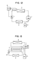
- a CO 2 cycle in a first preferred embodiment is applied to an automotive air conditioning apparatus.
- a compressor 1 is driven by an engine (not shown) for driving a vehicle via clutch means such as an electromagnetic clutch to compress gas phase CO 2 .
- a radiator (gas cooler) 2 cools CO 2 compressed by the compressor 1 by exchanging heat with outside air.
- a pressure control valve 3 controls a pressure at an outlet side of the radiator 2 in accordance with a temperature of CO 2 at the outlet side of the radiator 2.
- the pressure control valve 3 also functions as a decompressor. CO 2 is decompressed by the pressure control valve 3 to be low-temperature and low-pressure gas-liquid two phase CO 2 .
- An evaporator (heat sink) 4 functions as air cooling means for cooling air inside a passenger compartment of the vehicle.
- the gas-liquid two phase CO 2 is vaporized (evaporated) within the evaporator 4 while absorbing evaporation latent from air inside the passenger compartment, so that the air inside the passenger compartment is cooled.
- An accumulator (tank member) 5 separates the gas-liquid two phase CO 2 into gas phase CO 2 and liquid phase CO 2 , and temporarily accumulates the liquid phase CO 2 therein.
- the compressor 1, the radiator 2, the pressure control valve 3, the evaporator 4, and the accumulator 5 are respectively connected to one another through pipes to constitute a closed circuit.
- the radiator 2 is disposed on a vehicle front side more than another radiator (not shown) so that a temperature difference between CO 2 inside the radiator 2 and outside air becomes as large as possible.
- a casing 301 forms a part of a CO 2 passage 6a extending from the radiator 2 to the evaporator 4, and accommodates an element case 315 described later.
- An upper lid 301a has an inlet 301b connected to the radiator side.
- a casing main portion 301c has an outlet 301d connected to the evaporator side.
- the casing 301 has a partition wall 302 for partitioning the CO 2 passage 6a into an upstream side space 301e and a downstream side space 301f.
- the partition wall 302 has a valve orifice 303, through which the upstream side space 301e and the downstream side space 301f communicate with each other.
- the valve orifice 303 is opened and closed by a valve member 304 having a shape of a needle.
- the valve member 304 works with a diaphragm (pressure responsive member) 306 described later to close the valve orifice 303 when the diaphragm 306 moves from a neutral position toward the valve member 304 (a lower end of the diaphragm 306 in a thickness direction).
- an opening degree of the valve orifice 303 (displacement amount of the valve member 304 from a position when the valve orifice 303 is fully closed) becomes the maximum when the diaphragm 306 moves toward an upper end of the diaphragm 306 in the thickness direction.
- the diaphragm 306 is at the neutral position, the diaphragm 306 is not deformed and not displaced, so that stress produced by the deformed and displaced diaphragm 306 is substantially zero.
- a sealed space (gas-filled room) 305 is formed inside the upstream side space 301e.
- the sealed space 305 is defined by the thin-film diaphragm 306, and a diaphragm upper-side supporting member (forming member) 307 disposed on the upper end side of the diaphragm 306 in the thickness direction.
- the diaphragm 306 is made of stainless steel and is deformed and displaced in response to a pressure difference between inside and outside pressures of the sealed space 305.
- a diaphragm lower-side supporting member (holding member) 308 is disposed on the lower end side of the diaphragm 306 in the thickness direction to securely support the diaphragm 306 together with the upper-side supporting member 307.
- the lower-side supporting member 308 has a recess portion (holding member deformed portion) 308a at a position corresponding to a deformation facilitating portion (moving member deformed portion) 306a formed in the diaphragm 306.
- the recess portion 308a has a shape corresponding to the deformation facilitating portion 306a.
- the deformation facilitating portion 306a is formed by deforming a part of the diaphragm 306 at an external side in a diameter direction into a wave shape so that the diaphragm 306 is displaced and deformed substantially in proportion to the pressure difference between the inside and outside pressures of the sealed space 305.
- the lower-side supporting portion 308 has a lower-side flat portion (holding member flat portion) 308b. When the valve orifice 303 is closed by the valve member 304, the lower-side flat portion 308b is disposed substantially on the same surface as a contact surface 304a of the valve member 304 for making contact with the diaphragm 306.
- a first coil spring (first elastic member) 309 is disposed on the upper end side of the diaphragm 306 in the thickness direction (inside the sealed space 305).
- the first coil spring 309 applies elastic force to the valve member 304 through the diaphragm 306 so that the valve orifice 303 is closed.
- a second coil spring (second elastic member) 310 is disposed to apply elastic force to the valve member 304 so that the valve orifice 303 is opened.
- a plate (rigid body) 311 made of metal and having a specific thickness so that the plate 311 has rigidity larger than that of the diaphragm 306 is disposed between the diaphragm 306 and the first coil spring 309.
- the plate 311 functions as a spring seat for the first coil spring 309.
- the plate 311 makes contact with a step portion (stopper portion) 307a of the upper-side supporting member 307, thereby restricting the diaphragm 306 from being displaced more than a specific amount toward the upper end side of the diaphragm 306 in the thickness direction (toward the sealed space 305).
- the upper-side supporting member 307 has an upper-side flat portion (forming member flat portion) 307b.
- the upper-side flat portion 307b is disposed substantially on the same surface as a contact surface 311a of the plate 311 for making contact with the diaphragm 306.
- An inner wall of a cylindrical portion 307c of the upper-side supporting member 307 functions as a guiding wall for guiding the first coil spring 309.
- the plate 311 and the valve member 304 are pressed against the diaphragm 306 by the first and second coil springs 309, 310, respectively; therefore, the plate 311, the valve member 304, and the diaphragm 306 integrally move (operate) while making contact with one another.
- an adjustment screw (elastic force adjustment mechanism) 312 adjusts the elastic force applied to the valve member 304 by the second coil spring 310 and simultaneously functions as a plate for the second coil spring 310.
- the adjustment screw 312 is fastened to a female screw 302a formed on the partition wall 302.
- An initial load (elastic force when the valve orifice 303 is closed) by the first and second coil springs 309, 310 is approximately 1 MPa when it is converted to the pressure applied to the diaphragm 306.
- a sealing tube (piercing member) 313 is disposed to pierce the upper-side supporting member 307. CO 2 is sealed into the sealed space 305 through the sealing tube 313.
- the sealing tube 313 is made of a material having heat conductivity larger than that of the upper-side supporting member 307 made of stainless steel, such as copper.
- the lower-side supporting member 308 is also made of stainless steel.
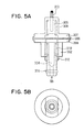
- FIG. 5A is a schematic view taken from an arrow VA in FIG. 2, showing the element case 315
- FIG. 5B is a top view taken from an arrow VB in FIG. 5A.
- the valve orifice 303 communicates with the upstream side space 301e at a side face side of the partition wall 302.
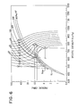
- the sealed space 305 is filled with CO 2 with a density of approximately 600 kg/m 3 ; therefore, a pressure and a temperature inside the sealed space 305 change along an isopycnic line of 600 kg/m 3 shown in FIG. 6.
- the pressure inside the sealed space 305 is approximately 5.8 MPa. Since both of the inside pressure of the sealed space 305 and the initial load of the first and second coil springs 309, 310 are applied to the valve member 304 simultaneously, an operation pressure applied to the valve member 304 is approximately 6.8 MPa. Therefore, when the pressure inside the upstream side space 301e on the radiator side is 6.8 MPa or lower, the valve orifice 303 is closed by the valve member 304. When the pressure inside the upstream side space 301e exceeds 6.8 MPa, the valve orifice 303 is opened.
- the pressure inside the sealed space 305 is approximately 9.7 MPa, and the operation force applied to the valve member 304 is approximately 10.7 MPa. Therefore, when the pressure inside the upstream side space 301e is 10.7 MPa or lower, the valve orifice 303 is closed by the valve member 304. When the pressure inside the upstream side space 301e exceeds 10.7 MPa, the valve orifice 303 is opened.
- the pressure control valve 3 opens.
- CO 2 is decompressed to perform phase transition from a gas phase to a gas-liquid two-phase (C-D), and flows into the evaporator 4.
- the gas-liquid two-phase CO 2 is evaporated inside the evaporator 4 (D-A) to cool air, and returns to the accumulator 5.
- the pressure on the outlet side of the radiator 2 decreases again, so that the pressure control valve 3 is closed again.
- CO 2 cycle after the pressure on the outlet side of the radiator 2 is increased to a specific pressure by closing the pressure control valve 3, CO 2 is decompressed and evaporated so that air is cooled.
- the pressure control valve 3 is opened when the pressure on the outlet side of the radiator 2 exceeds approximately 6.8 MPa.
- the valve orifice 303 (the CO 2 passage 6a) is closed. Therefore, even after the compressor 1 is stopped, the pressure on the high-pressure side can be prevented from decreasing. This does not cause increase in the manufacturing cost of the CO 2 cycle. Further, immediately after the compressor 1 is restarted, sufficient refrigerating capacity can be provided.
- FIGS. 7A and 7B are charts showing relations between ON-OFF timing of the electromagnetic clutch and the pressures on the high-pressure side (radiator side) and on the low-pressure side (evaporator side).
- FIG. 7A shows the relation in the CO 2 cycle in the first embodiment
- FIG. 7B shows the relation in a conventional CO 2 cycle.
- the pressure on the high-pressure side can be prevented from decreasing after the electromagnetic clutch is turned off.
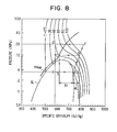
- the performance coefficient becomes the maximum at pressure P1 (approximately 10 MPa).
- the performance coefficient becomes the maximum at pressure P2 (approximately 9.0 MPa) as indicated by a broken line in FIG. 9.
- the deviation of the optimum control line ⁇ max from the isopycnic line of 600 kg/cm 3 becomes large when the pressure is lower than the critical pressure; however, because this range is a condensation range, the pressure inside the sealed space 305 varies along saturated liquid line SL. Further, because the initial load is applied to the valve element 304 by the coil springs 309, 310, the supercooling degree (sub-cooling) is controlled to be approximately 10°C. Therefore, even when the pressure is lower than the critical pressure, the CO 2 cycle can be effectively operated.
- the sealed space 305 it is desirable for a practical use that CO 2 is sealed with a saturated liquid density at a temperature in a range of 0°C to a critical point of CO 2 .
- the desirable density of CO 2 is in a range of 450 kg/cm 3 to 950 kg/cm 3 .
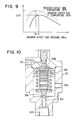
- the thin film diaphragm 306 is used as a pressure responsive member which moves in response to a pressure difference between inside and outside the sealed space 305; however, as shown FIG. 10, the pressure responsive member may be composed of a bellows 306b.
- the bellows 306b is disposed in the sealed space 305.
- the pressure control valve 3 used in the first embodiment is a mechanical type; however, a pressure control valve 7 used in a second preferred embodiment is an electric type.
- the pressure control valve 7 includes a housing 71 having an inlet 72 communicating with the outlet side of the radiator 2 and an outlet 73 communicating with the inlet side of the evaporator 4.
- a valve orifice 74 is provided in the housing 71 so that an inlet side space 72a and an outlet side space 73a communicate with each other through the valve orifice 74.
- a needle-like valve member 75 is further provided in the housing 71 to adjust an opening degree of the valve orifice 74.
- the valve member 75 is controlled by a step motor 76.
- the step motor 76 has a female screw portion 76b on a magnetic rotor 76a thereof, and the valve member 75 has a male screw portion 75a which is to be fastened to the female screw portion 76b.
- the opening degree of the valve orifice 74 (the opening degree of the pressure control valve 7) is continuously controlled from a fully closed state to a fully opened state, by a temperature sensor (temperature detecting member) 8 for detecting a radiator outlet side temperature of CO 2 , a pressure sensor (pressure detecting member) 9 for detecting a radiator outlet side pressure of CO 2 , and an electronic control unit (ECU) for rotating the step motor 76 based on ON-OFF signals of the electromagnetic clutch so that the step motor 76 moves the valve member 75 in an axial direction of the valve member 75.
- a temperature sensor temperature detecting member
- pressure sensor pressure detecting member 9
- ECU electronic control unit
- valve means such as an electromagnetic valve other than the pressure control valves 3, 7 may be disposed in the CO 2 passage to close the CO 2 passage when the compressor 1 is stopped.
- the supercritical refrigerating cycle (CO 2 cycle) according to the present invention is not limited to the automotive refrigeration cycle described above, and can be applied to a refrigerating cycle for an electric vehicle which dispenses with an electromagnetic clutch and includes an electric motor for driving an operational state of a compressor, stationary refrigerating cycles, and the like.
Landscapes
- Engineering & Computer Science (AREA)
- Physics & Mathematics (AREA)
- Thermal Sciences (AREA)
- Mechanical Engineering (AREA)
- General Engineering & Computer Science (AREA)
- Fluid Mechanics (AREA)
- Chemical & Material Sciences (AREA)
- Chemical Kinetics & Catalysis (AREA)
- Safety Valves (AREA)
- Control Of Positive-Displacement Pumps (AREA)
- Air-Conditioning For Vehicles (AREA)
Applications Claiming Priority (2)
| Application Number | Priority Date | Filing Date | Title |
|---|---|---|---|
| JP977798 | 1998-01-21 | ||
| JP10009777A JPH11211250A (ja) | 1998-01-21 | 1998-01-21 | 超臨界冷凍サイクル |
Publications (2)
| Publication Number | Publication Date |
|---|---|
| EP0931991A2 true EP0931991A2 (fr) | 1999-07-28 |
| EP0931991A3 EP0931991A3 (fr) | 1999-11-17 |
Family
ID=11729684
Family Applications (1)
| Application Number | Title | Priority Date | Filing Date |
|---|---|---|---|
| EP99101023A Withdrawn EP0931991A3 (fr) | 1998-01-21 | 1999-01-20 | Système frigorifique supercritique |
Country Status (3)
| Country | Link |
|---|---|
| US (1) | US6134900A (fr) |
| EP (1) | EP0931991A3 (fr) |
| JP (1) | JPH11211250A (fr) |
Cited By (5)
| Publication number | Priority date | Publication date | Assignee | Title |
|---|---|---|---|---|
| EP1202004A1 (fr) * | 2000-10-30 | 2002-05-02 | Calsonic Kansei Corporation | Cycle de refroidissement et procédé de commande associé |
| FR2862745A1 (fr) * | 2003-11-25 | 2005-05-27 | Valeo Climatisation | Organe de detente a electronique integree pour boucle a fluide refrigerant, en particulier d'un appareil de climatisation pour habitacle de vehicule |
| GB2473555A (en) * | 2008-05-13 | 2011-03-16 | Gen Electric | Method and apparatus for controlling fuel in a gas turbine engine |
| CN101548142B (zh) * | 2006-11-30 | 2013-04-24 | 开利公司 | 制冷剂充填料的储存 |
| CN102128525B (zh) * | 2010-01-13 | 2014-05-14 | 浙江三花股份有限公司 | 一种热力膨胀阀及使用该膨胀阀的制冷系统 |
Families Citing this family (16)
| Publication number | Priority date | Publication date | Assignee | Title |
|---|---|---|---|---|
| JP2000346472A (ja) * | 1999-06-08 | 2000-12-15 | Mitsubishi Heavy Ind Ltd | 超臨界蒸気圧縮サイクル |
| JP4586221B2 (ja) * | 1999-11-08 | 2010-11-24 | Nok株式会社 | 制御弁 |
| NO20005974D0 (no) * | 2000-11-24 | 2000-11-24 | Sinvent As | Kjöle- eller varmepumpesystem med varmeavgivelse ved endring i temperatur |
| US6543241B2 (en) * | 2000-12-04 | 2003-04-08 | Mikhail Levitin | Refrigerant feed device |
| EP1369648A3 (fr) * | 2002-06-04 | 2004-02-04 | Sanyo Electric Co., Ltd. | Système de cycle à frigorigène supercritique |
| US7044717B2 (en) * | 2002-06-11 | 2006-05-16 | Tecumseh Products Company | Lubrication of a hermetic carbon dioxide compressor |
| US6591618B1 (en) * | 2002-08-12 | 2003-07-15 | Praxair Technology, Inc. | Supercritical refrigeration system |
| US6626000B1 (en) * | 2002-10-30 | 2003-09-30 | Visteon Global Technologies, Inc. | Method and system for electronically controlled high side pressure regulation in a vapor compression cycle |
| TWI324242B (en) * | 2004-02-12 | 2010-05-01 | Sanyo Electric Co | Refrigerant cycle apparatus |
| JP2005265278A (ja) * | 2004-03-18 | 2005-09-29 | Daikin Ind Ltd | 冷凍装置 |
| US20060059945A1 (en) * | 2004-09-13 | 2006-03-23 | Lalit Chordia | Method for single-phase supercritical carbon dioxide cooling |
| JP5055965B2 (ja) * | 2006-11-13 | 2012-10-24 | ダイキン工業株式会社 | 空気調和装置 |
| DE102014214656A1 (de) * | 2014-07-25 | 2016-01-28 | Konvekta Ag | Kompressionskälteanlage und Verfahren zum Betrieb einer Kompressionskälteanlage |
| JP7113553B2 (ja) * | 2019-12-25 | 2022-08-05 | 株式会社不二工機 | 流量調整弁 |
| US11721858B2 (en) | 2020-12-11 | 2023-08-08 | Kesavan Moses Srivilliputhur | SuCCoR: a super critical cooling regulator to mitigate heating of batteries and other devices |
| CN113758039B (zh) * | 2021-04-30 | 2022-11-01 | 中国科学院理化技术研究所 | 自然工质co2压缩-超音速两相膨胀复合制冷系统及制冷机 |
Citations (1)
| Publication number | Priority date | Publication date | Assignee | Title |
|---|---|---|---|---|
| WO1990007683A1 (fr) | 1989-01-09 | 1990-07-12 | Sinvent As | Dispositif a cycle de carnot renverse en conditions transcritiques |
Family Cites Families (19)
| Publication number | Priority date | Publication date | Assignee | Title |
|---|---|---|---|---|
| US1782687A (en) * | 1927-08-01 | 1930-11-25 | Baker Ice Machine Co Inc | Refrigerating apparatus |
| US2148412A (en) * | 1933-01-19 | 1939-02-21 | Westinghouse Electric & Mfg Co | Refrigerating apparatus |
| US2245454A (en) * | 1937-09-24 | 1941-06-10 | Gen Motors Corp | Refrigerating apparatus |
| US2331264A (en) * | 1940-05-17 | 1943-10-05 | Detroit Lubricator Co | Refrigerating system |
| US2326093A (en) * | 1940-05-29 | 1943-08-03 | Detroit Lubricator Co | Refrigerating system |
| US4081971A (en) * | 1976-09-17 | 1978-04-04 | The Trane Company | Air cooled centrifugal refrigeration machine with provision to prevent evaporator freezing |
| US4267702A (en) * | 1979-08-13 | 1981-05-19 | Ranco Incorporated | Refrigeration system with refrigerant flow controlling valve |
| US4286438A (en) * | 1980-05-02 | 1981-09-01 | Whirlpool Corporation | Condition responsive liquid line valve for refrigeration appliance |
| JPS59104050A (ja) * | 1982-12-02 | 1984-06-15 | 松下冷機株式会社 | 冷凍装置 |
| US4852364A (en) * | 1987-10-23 | 1989-08-01 | Sporlan Valve Company | Expansion and check valve combination |
| US5245836A (en) * | 1989-01-09 | 1993-09-21 | Sinvent As | Method and device for high side pressure regulation in transcritical vapor compression cycle |
| EP0504775A3 (en) * | 1991-03-19 | 1993-01-20 | Ranco Incorporated Of Delaware | Refrigeration system subcooling flow control valve |
| US5205131A (en) * | 1991-03-19 | 1993-04-27 | White Consoldiated Industries, Inc. | Refrigerator system with subcooling flow control |
| ES2088502T3 (es) * | 1991-09-16 | 1996-08-16 | Sinvent As | Control de presion en el lado de alta presion en un ciclo de compresion de vapor transcritico. |
| DE4432272C2 (de) * | 1994-09-09 | 1997-05-15 | Daimler Benz Ag | Verfahren zum Betreiben einer Kälteerzeugungsanlage für das Klimatisieren von Fahrzeugen und eine Kälteerzeugungsanlage zur Durchführung desselben |
| US5533353A (en) * | 1994-12-16 | 1996-07-09 | Chrysler Corporation | Method and apparatus for controlling the clutch of an air conditioner system |
| JP3858297B2 (ja) * | 1996-01-25 | 2006-12-13 | 株式会社デンソー | 圧力制御弁と蒸気圧縮式冷凍サイクル |
| EP0837291B1 (fr) * | 1996-08-22 | 2005-01-12 | Denso Corporation | Système frigorifique du type à compression de vapeur |
| EP0892226B1 (fr) * | 1997-07-18 | 2005-09-14 | Denso Corporation | Soupape de commande de pression pour système frigorifique |
-
1998
- 1998-01-21 JP JP10009777A patent/JPH11211250A/ja active Pending
-
1999
- 1999-01-20 US US09/234,188 patent/US6134900A/en not_active Expired - Fee Related
- 1999-01-20 EP EP99101023A patent/EP0931991A3/fr not_active Withdrawn
Patent Citations (1)
| Publication number | Priority date | Publication date | Assignee | Title |
|---|---|---|---|---|
| WO1990007683A1 (fr) | 1989-01-09 | 1990-07-12 | Sinvent As | Dispositif a cycle de carnot renverse en conditions transcritiques |
Cited By (8)
| Publication number | Priority date | Publication date | Assignee | Title |
|---|---|---|---|---|
| EP1202004A1 (fr) * | 2000-10-30 | 2002-05-02 | Calsonic Kansei Corporation | Cycle de refroidissement et procédé de commande associé |
| US6523360B2 (en) | 2000-10-30 | 2003-02-25 | Calsonic Kansei Corporation | Cooling cycle and control method thereof |
| FR2862745A1 (fr) * | 2003-11-25 | 2005-05-27 | Valeo Climatisation | Organe de detente a electronique integree pour boucle a fluide refrigerant, en particulier d'un appareil de climatisation pour habitacle de vehicule |
| EP1536193A1 (fr) * | 2003-11-25 | 2005-06-01 | Valeo Climatisation | Organe de détente à électronique intégrée pour boucle à fluide réfrigérant, en particulier d'un appareil de climatisation pour habitacle de véhicule |
| CN101548142B (zh) * | 2006-11-30 | 2013-04-24 | 开利公司 | 制冷剂充填料的储存 |
| GB2473555A (en) * | 2008-05-13 | 2011-03-16 | Gen Electric | Method and apparatus for controlling fuel in a gas turbine engine |
| GB2473555B (en) * | 2008-05-13 | 2012-06-20 | Gen Electric | Thermal management of fuel in gas turbine engines |
| CN102128525B (zh) * | 2010-01-13 | 2014-05-14 | 浙江三花股份有限公司 | 一种热力膨胀阀及使用该膨胀阀的制冷系统 |
Also Published As
| Publication number | Publication date |
|---|---|
| JPH11211250A (ja) | 1999-08-06 |
| EP0931991A3 (fr) | 1999-11-17 |
| US6134900A (en) | 2000-10-24 |
Similar Documents
| Publication | Publication Date | Title |
|---|---|---|
| US6134900A (en) | Supercritical refrigerating system | |
| EP0915306B1 (fr) | Appareil frigorifigue supercritique | |
| JP4045654B2 (ja) | 超臨界冷凍サイクル | |
| US5890370A (en) | Refrigerating system with pressure control valve | |
| USRE42908E1 (en) | Vapor-compression-type refrigerating machine | |
| US11391499B2 (en) | Heat pump cycle device and valve device | |
| EP0892226B1 (fr) | Soupape de commande de pression pour système frigorifique | |
| JPH10115470A (ja) | 蒸気圧縮式冷凍サイクル | |
| JPH0949662A (ja) | 圧縮式空調機 | |
| JP4207235B2 (ja) | 蒸気圧縮式冷凍サイクル | |
| US20050262873A1 (en) | Refrigeration cycle | |
| JP3467989B2 (ja) | 蒸気圧縮式冷凍サイクル | |
| JPH09229497A (ja) | 冷凍サイクル | |
| JP4196450B2 (ja) | 超臨界冷凍サイクル | |
| US6694760B2 (en) | Refrigerating cycle | |
| JP3867370B2 (ja) | 冷媒封入方法 | |
| JP3528433B2 (ja) | 蒸気圧縮式冷凍サイクル | |
| JPH1163739A (ja) | 圧力制御弁 | |
| JPH11148576A (ja) | 圧力制御弁 | |
| JP3879772B2 (ja) | 冷凍装置 | |
| JP3826503B2 (ja) | 圧力制御弁 | |
| JP3787968B2 (ja) | 圧力制御弁 | |
| EP1162417A1 (fr) | Detendeur | |
| JPH10220888A (ja) | 冷凍サイクル | |
| JP3711718B2 (ja) | 圧力制御弁 |
Legal Events
| Date | Code | Title | Description |
|---|---|---|---|
| PUAI | Public reference made under article 153(3) epc to a published international application that has entered the european phase |
Free format text: ORIGINAL CODE: 0009012 |
|
| AK | Designated contracting states |
Kind code of ref document: A2 Designated state(s): DE FR GB |
|
| AX | Request for extension of the european patent |
Free format text: AL;LT;LV;MK;RO;SI |
|
| PUAL | Search report despatched |
Free format text: ORIGINAL CODE: 0009013 |
|
| AK | Designated contracting states |
Kind code of ref document: A3 Designated state(s): AT BE CH CY DE DK ES FI FR GB GR IE IT LI LU MC NL PT SE |
|
| AX | Request for extension of the european patent |
Free format text: AL;LT;LV;MK;RO;SI |
|
| RIC1 | Information provided on ipc code assigned before grant |
Free format text: 6F 25B 9/00 A, 6F 25B 41/06 B, 6G 05D 23/12 B, 6F 25B 41/04 B |
|
| 17P | Request for examination filed |
Effective date: 20000105 |
|
| AKX | Designation fees paid |
Free format text: DE FR GB |
|
| 17Q | First examination report despatched |
Effective date: 20020812 |
|
| STAA | Information on the status of an ep patent application or granted ep patent |
Free format text: STATUS: THE APPLICATION IS DEEMED TO BE WITHDRAWN |
|
| 18D | Application deemed to be withdrawn |
Effective date: 20021224 |