EP0929068A2 - Verfahren und Gerät zur Wiedergabe einer Vielzahl von Informationsstücken - Google Patents
Verfahren und Gerät zur Wiedergabe einer Vielzahl von Informationsstücken Download PDFInfo
- Publication number
- EP0929068A2 EP0929068A2 EP99100014A EP99100014A EP0929068A2 EP 0929068 A2 EP0929068 A2 EP 0929068A2 EP 99100014 A EP99100014 A EP 99100014A EP 99100014 A EP99100014 A EP 99100014A EP 0929068 A2 EP0929068 A2 EP 0929068A2
- Authority
- EP
- European Patent Office
- Prior art keywords
- information
- compressed information
- information pieces
- piece
- pieces
- Prior art date
- Legal status (The legal status is an assumption and is not a legal conclusion. Google has not performed a legal analysis and makes no representation as to the accuracy of the status listed.)
- Granted
Links
Images


Classifications
-
- G—PHYSICS
- G11—INFORMATION STORAGE
- G11B—INFORMATION STORAGE BASED ON RELATIVE MOVEMENT BETWEEN RECORD CARRIER AND TRANSDUCER
- G11B27/00—Editing; Indexing; Addressing; Timing or synchronising; Monitoring; Measuring tape travel
- G11B27/10—Indexing; Addressing; Timing or synchronising; Measuring tape travel
- G11B27/11—Indexing; Addressing; Timing or synchronising; Measuring tape travel by using information not detectable on the record carrier
-
- G—PHYSICS
- G11—INFORMATION STORAGE
- G11B—INFORMATION STORAGE BASED ON RELATIVE MOVEMENT BETWEEN RECORD CARRIER AND TRANSDUCER
- G11B20/00—Signal processing not specific to the method of recording or reproducing; Circuits therefor
- G11B20/00007—Time or data compression or expansion
-
- G—PHYSICS
- G11—INFORMATION STORAGE
- G11B—INFORMATION STORAGE BASED ON RELATIVE MOVEMENT BETWEEN RECORD CARRIER AND TRANSDUCER
- G11B20/00—Signal processing not specific to the method of recording or reproducing; Circuits therefor
- G11B20/10—Digital recording or reproducing
- G11B20/10527—Audio or video recording; Data buffering arrangements
-
- G—PHYSICS
- G11—INFORMATION STORAGE
- G11B—INFORMATION STORAGE BASED ON RELATIVE MOVEMENT BETWEEN RECORD CARRIER AND TRANSDUCER
- G11B27/00—Editing; Indexing; Addressing; Timing or synchronising; Monitoring; Measuring tape travel
- G11B27/10—Indexing; Addressing; Timing or synchronising; Measuring tape travel
- G11B27/102—Programmed access in sequence to addressed parts of tracks of operating record carriers
- G11B27/105—Programmed access in sequence to addressed parts of tracks of operating record carriers of operating discs
-
- G—PHYSICS
- G11—INFORMATION STORAGE
- G11B—INFORMATION STORAGE BASED ON RELATIVE MOVEMENT BETWEEN RECORD CARRIER AND TRANSDUCER
- G11B27/00—Editing; Indexing; Addressing; Timing or synchronising; Monitoring; Measuring tape travel
- G11B27/10—Indexing; Addressing; Timing or synchronising; Measuring tape travel
- G11B27/19—Indexing; Addressing; Timing or synchronising; Measuring tape travel by using information detectable on the record carrier
- G11B27/22—Means responsive to presence or absence of recorded information signals
Definitions
- the present invention relates to an information reproducing method and an information reproducing apparatus for reading information pieces recorded on a record medium, such as an MD (Mini Disc) or the like and then demodulating it.
- a record medium such as an MD (Mini Disc) or the like
- An MD player is an information reproducing apparatus for reading compressed information recorded on an MD and then demodulating it.
- the MD is one of record mediums.
- Compressed information for example, compressed digital audio data is spirally recorded on the MD.
- the compressed information is divided into a plurality of compressed information pieces. In other words, the compressed information is recorded at a unit of information piece.
- this information piece is referred to as "compressed information piece”. For example, if the compressed information is a music, one compressed information piece is a song.
- control information indicative of a record position (for example, an address)-of the compressed information piece together with the compressed information is recorded on the MD.
- the MD player is provided with: a spindle motor for rotating the MD; a pickup for optically reading the compressed information recorded on the MD; a servo controller for controlling a movement of the pickup on the MD; a signal processor for demodulating the compressed information read by the pickup; a key input section for receiving a command from a user; and a system controller for controlling the MD player as a whole.
- the MD player is operated as follows.
- the pickup radiates a laser light toward the rotating MD.
- the pickup receives the laser light reflected by the MD, and then converts the laser light into an electrical signal.
- This electrical signal contains the compressed information recorded on the MD.
- the signal processor receives the electrical signal outputted by the pickup, and then demodulates it. Accordingly, the compressed information is reproduced.
- the pickup In order to read out the compressed information recorded on the MD by using the pickup, it is necessary to accurately control a radiation position (namely, a read position) of the laser light radiated by the pickup. This is achieved by the servo controller.
- the electrical signal outputted by the pickup contains the information with regard to the read position of the pickup.
- the servo controller controls the read position of the pickup based on this information
- the MD player not only can simply reproduce the plurality-of compressed information pieces recorded on the MD, but also can change a reproduction order of the compressed information pieces based on a user indication. For example, if the MD on which a plurality of songs are recorded is reproduced by the MD player, the user can select several songs from the plurality of songs to then set the reproduction order of the songs. When the reproduction order of the songs is inputted, the MD player reproduces the songs in the inputted reproduction order.
- a silent portion (a blank portion) exists between the songs. That is, in order to clarify a pause between the songs, each song is recorded so as to be kept silent for a few seconds at the beginning of each song. In case of a song whose ending is fade-out, a level of a musical sound becomes gradually lower at the ending of the song.
- the musical sound is erased by a noise within the running car.
- the driver can not hear the ending of the song, and thereby feels that a period from the end of the song to the start of the next song is long. In other words, the user feels that the blank between the compressed information pieces is long.
- the level of the musical sound is low at the beginning of the song. Also in this case, the driver can not hear the beginning of the song, and thereby feels that the period between the songs is long. In other words, the user feels that the blank between the compressed information pieces is long.
- Such a problem is not limited to the case in which the MD is reproduced within the running car.
- the problem may be brought about even in a case that the MD is reproduced in a room where the noise is relatively large, an outdoor and the like.
- the present invention is proposed in view of the above-mentioned problems. It is therefore a first object of the present invention to provide an information reproducing method and an information reproducing apparatus which can prevent a user from feeling that a blank at a boundary between continuously reproduced information pieces is long when information composed of a plurality of information pieces is continuously reproduced from a record medium.
- a second object of the present invention is to provide an information reproducing method and an information reproducing apparatus which can prevent a user from feeling that a connection between continuously reproduced information pieces is unnatural when information composed of a plurality of information pieces is continuously reproduced.
- the aforementioned first object can be achieved by an information reproducing apparatus in accordance with the present invention.
- the information reproducing apparatus is an apparatus for reproducing a plurality of information pieces recorded on a recording medium.
- the apparatus has: a reading device for reading the information pieces from the recording medium in accordance with a predetermined reproduction order; a linking device for linking the information pieces read by the reading device with each other, by removing either or both of a beginning and an ending of each of the information pieces; and a converting device for converting the information pieces linked by the linking device into a reproduction signal to be supplied to an output device.
- Information is recorded on the recording medium.
- the information is divided into the information pieces on the recording medium.
- the information pieces read from the recording medium by the reading device. Then, either or both of the beginning and the ending of these information pieces are removed, and then, they are linked with each other. Therefore, information for the purpose of identifying the boundary between the information pieces, such as a blank part, a fade-out part, a fade-in part, etc., as mentioned above, can be removed, and the information pieces can be linked in such a way that they are continuously reproduced without a pause.
- the linking device may include: a read position detecting device for detecting a read position of the reading device on the recording medium; and a read position control device for controlling a movement of the read position of the reading device on the recording medium.
- the read position detecting device detects a first read position corresponding to a first position of each of the information pieces, which is located in the vicinity of the ending of each of the information pieces. Then, the read position control device controls the movement of the read position such that the read position jumps from the first read position to a second read position corresponding to a second position of each of the information pieces, which is located in the vicinity of the beginning of each of the information pieces.
- the linking device may include a storing device for storing the information pieces read by the reading device such that the first position of each of the information pieces is linked with the second position of each of the information pieces in accordance with the reproduction order.
- a first information piece is firstly read by the reading device, and stored in the storing device.
- the first information piece except for the area located between the first position of this information piece and the edge of the ending of this information piece is stored in the storing device.
- a second information piece is read by the reading device, and stored in the storing device.
- the second information piece except for the area located between the edge of the beginning of this information piece and the second position of this information piece is stored in the storing device. Since the second information piece and the second information piece are continuously stored in the storing device, the first position of the first information piece and the second position of the second information piece are linked with each other.
- the first position may be located within the information piece and located a predetermined distance away from the edge of the ending of this information piece. As a result, the area between the first position and the edge of the ending of the information piece is removed by the linking device. If the blank part or the fade-out part is included in this area, the blank part or the fade-out part is removed from the information piece.
- the first position may be located at the edge of the ending of each of the information pieces. As a result, no area located in the ending of the information pieces is removed. In addition, in this case, it is necessary to remove the area located in the beginning of the information piece.
- the second position may be located within the information piece and located a predetermined distance away from the edge of the beginning of this information piece. As a result, the area between the edge of the beginning of the information piece and the second position is removed by the linking device. If the blank part or the fade-in part is included in this area, the blank part or the fade-is part is removed from the information piece.
- the second position may be located at the edge of the beginning of each of the information pieces. As a result, no area located in the beginning of the information pieces is removed. In addition, in this case, it is necessary to remove the area located in the ending of the information piece.
- the information reproducing apparatus may include a volume control device for controlling a volume of the audio signal corresponding to the audio information included in each of the information pieces. Further, in this case, the volume control device may control the volume such that the volume gradually decreases from a third position of the information piece, which is located a predetermined distance away from the first position of this information piece, to the first position of this information piece. Furthermore, the volume control device may control the volume such that the volume gradually increases from the second position of the information piece to a forth position of this information piece, which is located a predetermined distance away from the second position of this information piece.
- the volume control device serves to compensate unnaturalness caused by linkage of the information pieces by the linking device, if the linkage is unnatural.
- the volume control devise perform the volume control on the first information piece such that the volume of the audio signal corresponding to the area between the third position and the first position gradually decreases. This area is located at the ending of each information piece included in the liked information pieces. At this time, the amount of the decrease of the volume is decided for the purpose of the compensation of unnaturalness caused by the linkage of the information pieces.
- the volume control device perform the volume control on the second information piece such that the volume of the audio signal corresponding to the area between the second position and the forth position gradually increases. This area is located at the beginning of each information piece included in the linked information pieces. At this time, the amount of the increase of the volume is decided for the purpose of the compensation of unnaturalness caused by the linkage-of the information pieces.
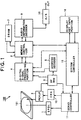
- an MD player 100 is an information reproducing apparatus for reading compressed information recorded on an MD 101 and then demodulating it.
- the MD 101 is one of information record mediums. Compression information, for example, compressed digital audio data is recorded on the MD 101.
- the compressed information is divided into a plurality of compressed information pieces. In other words, the compressed information is recorded at a unit of compressed information piece. For example, if the compressed information is a music, one compressed information piece is a song.
- control information indicative of a record position (for example, an address) of the compressed information piece together with the compressed information is recorded on the MD 101.
- the inherent data (for example, TOC information) with regard to each compressed information piece, such as a start address, an end address, a number of the compressed information piece and the like, in each compressed information piece is recorded on this information area in accordance with a predetermined recording format.
- the MD player 100 is provided with a spindle motor (SPDL) 1, a pickup 2, an RF amplifier 3, a digital signal processing portion 4, an address decoder 5, a memory controller 6, a DRAM (Dynamic Random Access Memory) 7, a system controller 15, an audio information decoder 9, a D/A (digital to analog) converter 10, a servo controller 11, a pickup carriage (CRG) 12 and a display key input portion 16.
- the MD player 100 is operated as follows.
- a user loads the MD 101 into the MD player 100, and then uses the display key input portion 16, and further enters a command into the MD player 100
- the pickup 2 radiates a laser light toward the MD 101.
- the system controller 15 controls the servo controller 11 such that the laser light is focused on the MD 101.
- the system controller 15 drives the spindle motor 1 to then rotate the MD 101 at a predetermined speed. Then, the system controller 15 drives the pickup carriage 12, and then moves the pickup 2 in order to read the information recorded on the MD 101 in accordance with an inputted operation command.
- the pickup 2 radiates the laser light to an information record surface of the MD 101, and then receives the laser light reflected on the MD 101.
- the pickup 2 converts the received laser light into an electrical signal.
- This electrical signal is sent to the RF amplifier 3 as an RF (Radio Frequency) signal.
- the RF amplifier 3 sends this RF signal to the digital signal processing portion 4 and the address decoder 5. Then, the RF amplifier 3 generates an error signal on the basis of this RF signal, and then sends this error signal to the servo controller 11. Accordingly, a read error of the pickup 2 is corrected.
- the address decoder 5 demodulates address data indicative of a present read position of the pickup 2 on the basis of the RF signal, and then sends this address data to the digital signal processing portion 4.
- the digital signal processing portion 4 amplifies the RF signal sent by the RF amplifier 3, and then converts this RF signal into a binary value by using a predetermined slice level. Then, the digital signal processing portion 4 performs an EFM demodulation and an error correction process on the binary RF signal. Accordingly, the compressed information is restored. Then, this compressed information together with the address data is sent from the digital signal processing portion 4 to the memory controller 6.
- the memory controller 6 transfers the compressed information to the DRAM 7 under the control of the system controller 15.
- the transfer order of the compressed information is determined in accordance with the address data.
- the DRAM 7 stores the transferred compressed information and further transfers the stored compressed information to the audio information decoder 9 in the recorded order.
- the transfer speed of the compressed information transferred to the DRAM 7 from the memory controller 6 is faster than that of the compressed information transferred to the audio information decoder 9 from the DRAM 7. Accordingly, the compressed information transferred from the memory controller 6 is stored in the DRAM 7 until the amount of the compressed information stored in the DRAM 7 reaches the upper limit of the capacity of the DRAM 7. In this way, the DRAM 7 functions as a buffer memory for temporarily storing the data read by the pickup 2.
- the audio information decoder 9 expands the compressed information transferred by the DRAM 7, and then prepares digital audio data, and further sends it to the D/A converter 10.
- the D/A converter 10 converts this digital audio data into an analog audio signal, and then outputs it from an output terminal. This analog audio signal is sent through an amplifier (not shown) to a speaker and the like (not shown).
- the servo controller 11 While the pickup 2 reads the information recorded on the MD 101, the servo controller 11 carries out a focus control and a tracking control with regard to the pickup 2, on the basis of the error signal sent by the RF amplifier 3, and further controls the rotation of the spindle motor 1. Accordingly, the pickup 2 is controlled so as to accurately read the information recorded on the MD 101.
- the MD player 100 before reading the compressed information recorded on the MD 101, reads the inherent data with regard to the compressed information piece (this data includes the start address of the compressed information), from the information area located on the inner circumference side of the MD 101. Then, they are stored in an internal memory within the system controller 15.
- the system controller 15 detects address data corresponding to a present read position of the pickup 2 on the basis of the RF signal. Then, the system controller 15 reads out the start address of the specified compressed information piece from the internal memory. Then, the system controller 15 compares the read out start address with the address data corresponding to the present read position of the pickup 2. Next, the system controller 15 controls the servo controller 11 based on the comparison result, and then moves (jumps) the pickup 2. Accordingly, the read position of the pickup 2 can be moved to the start address of the specified compressed information piece to thereby read this compressed information piece.
- the MD player 100 can select any one or more compressed information pieces from a plurality of compressed information pieces recorded on the MD 101 and then set the reproduction order of the selected compressed information pieces. More specifically, when the user uses display key input portion 16 and then selects a plurality of compressed information pieces and further sets the reproduction order of the selected compressed information pieces, the numbers of the compressed information pieces arrayed on the basis of the reproduction order are stored in the internal memory within the system controller 15.
- the system controller 15 controls the servo controller 11, and then jumps the pickup 2 in accordance with the number of the compressed information piece stored in the internal memory. Actually, the system controller 15, immediately after reading a compressed information piece, jumps the pickup 2 toward a start address of a next compressed information piece in accordance with the number of the compressed information piece. The repetition of such a reading and jumping operation enables the compressed information piece to be reproduced in the reproduction order set by the user.
- the system controller 15 controls the memory controller 6 so as to suspend the transfer of the compressed information to the DRAM 7 from the memory controller 6. Moreover, when the jump of the pickup 2 is ended and then the information reading operation of the pickup 2 is resumed, the system controller 15 controls the memory controller 6 so as to resume the transfer of the compressed information to the DRAM 7 from the memory controller 6. Accordingly, the compressed information read immediately after the information reading operation of the pickup 2 is resumed is stored immediately after the compressed information read immediately before the information reading operation of the pickup 2 is suspended. Thus, the compressed information read before the jump and the compressed information read after the jump are continuously stored in the DRAM 7.
- the memory controller 6 always recognizes the address data sent by the digital signal processing portion 4 together with the compressed information, and then manages the transfer order of the compressed information in accordance with the address data. If the read position of the pickup 2 is out of the normal position because of addition of external shock or the like to the pickup 2 during reading the compressed information, the system controller 8 recognizes an address immediately before the read position of the pickup 2 is out of the normal position through the memory controller 6. Then, the system controller 8 controls the servo controller 11 so as to return the read position of the pickup 2 to the normal position, based on this address.
- the system controller 8 controls the memory controller 6 so as to suspend the transfer of the compressed information to the DRAM 7 from the memory controller 6. Then, when the read position of the pickup 2 is returned to the normal position, the system controller 8 controls the memory controller 6 so as to resume the transfer of the compressed information to the DRAM 7 from the memory controller 6.
- the compressed information read before the read position becomes out of the normal position and the compressed information read after the read position is returned to the normal position are continuously stored in the DRAM 7.
- the period while the read position of the pickup 2 is out of the normal position is shorter than the period until all the compressed information stored in the DRAM 7 is transferred to the audio information decoder 9, the compressed information is continuously reproduced without a disconnection.
- the MD player 100 has a linking function, in addition to the basic reproducing function as mentioned above.
- the linking function is a function that links a plurality of compressed information pieces by removing a silent portion (that is, a blank portion) between the compressed information pieces, the ending of the compressed information piece or the beginning of the compressed information piece, when continuously reproducing a plurality of compressed information pieces.
- the compressed information pieces are songs
- the liking function is a function that links the plurality of songs by removing a silent portion between the songs, the ending of the song ending (a fade-out portion) and the beginning of the song (a fade-in portion).
- the silent portion between the songs is recorded on the MD as the compressed information indicating the silence.
- This silent portion constitutes a part of the song, namely, the compressed information piece.
- this silent portion is located at the beginning of the compressed information piece.
- each of the fade-out portion located at the ending of the song and the fade-in portion located at the beginning of the song also constitutes a part of the song, namely, the compressed information piece.
- the MD player 100 continuously reproduces the compressed information recorded on the MD 101.
- the MD player 100 usually reproduces the silent portion similarly to the other portions.
- the MD player 100 usually reproduces the fade-out portion and the fade-in portion similarly to the other portions.
- a reproduction sound may become actually intermittent, and a sound volume may become smaller.
- the fade-in portion implies the portion at which the sound volume of the reproduction sound corresponding to the compressed information does not reach a predetermined level, at the beginning of the compressed information piece.
- the fade-out portion implies the portion at which the sound volume of the reproduction sound corresponding to the compressed information does not reach a predetermined level, at the ending of the compressed information piece.
- the MD player 100 reproduces the compressed information at a reproduction mode different from the above-mentioned usual reproduction mode. That is, the MD player 100, when reproducing the compressed information, removes the silent portion, the fade-out portion and the fade-in portion in the compressed information stored in the MD 101, in accordance with a predetermined condition as described later. As a result, a silent portion located at a boundary between the compressed information pieces and a portion in which the sound volume is small are removed, and thereby the reproduction sound becomes actually continuous throughout the plurality of compressed information pieces.
- the display key input portion 16 has a mode selection key to execute the linking function.
- the linking function is executed in the MD player 100.
- the memory controller 6 removes the compressed information located at the silent portion between the compressed information pieces, the ending of the compressed information piece and the beginning of the compressed information piece under the control of the system controller 15, when transferring to the DRAM 7 the compressed information supplied at the specified reproduction order.
- the compressed information stored in the DRAM 7 is continuously read out as mentioned above. Accordingly, the ending of the compressed information piece and the beginning of a next compressed information piece following it are linked and restored continuously and integrally.
- FIG.2 is a diagrammatic view showing a state that the compressed information recorded on the MD 101 for each compressed information piece is stored in the DRAM 7 by using the linking function.
- (A) in FIG.2 shows the compressed information recorded on the MD 101.
- the linking function is not executed, namely, at a time of the usual reproduction mode, the compressed information is stored in the DRAM 7 while maintaining this state.
- (B) in FIG.2 shows a state that the compressed information shown at (A) is stored in the DRAM 7, during executing the linking function.
- the compressed information located on and after tb1 within the first compressed information piece T1 and the compressed information located before ta2 within the second compressed information piece T2 are removed.
- the compressed information corresponding to the first compressed information piece T1 and the compressed information corresponding to the second compressed information piece T2 are linked with each other.
- the compressed information located on and after tb2 within the second compressed information piece T2 and the compressed information located before ta3 within the third compressed information piece T3 are removed.
- the compressed information corresponding to the second compressed information piece T2 and the compressed information corresponding to the third compressed information piece T3 are linked with each other.
- the similar process is performed on the other compressed information pieces. In this manner, the predetermined portions located at the beginning and ending of each compressed information piece are removed, and the remaining parts of the compressed information are linked with each other and stored into the DRAM 7.
- the respective positions ta2, ta3, ..., taN are located behind the edge of the beginning of each compressed information piece in time and located in the vicinity of the beginning of each compressed information piece.
- the compressed information corresponding to the above-mentioned silent portion and fade-in portion are included from the edge of the beginning of each compressed information piece to the respective positions ta2, ta3, ..., taN.
- the respective positions tb1, tb2, tb3, ..., tbN are located before the edge of the ending of each compressed information piece in time and located in the vicinity of the ending of each compressed information piece.
- the compressed information corresponding to the above-mentioned fade-out portion and silent portion are included from the respective positions tb1, tb2, tb3, ..., tbN to the edge of the ending of each compressed information.
- FIG.3 shows the transfer control process of the compressed information to the DRAM 7 when this linking function is executed.
- This transfer control process is mainly executed by the system controller 15, as follows.
- a user uses the display key input portion 16, and then selects several desirable compressed information pieces from a plurality of compressed information pieces recorded on the MD 101, and further sets a reproduction order of the selected compressed information pieces.
- This reproduction order is stored in the internal memory of the system controller 15.
- the reproduction order is automatically set in accordance with reproduction order information (this is included in the TOC information) stored in the MD 101.
- the system controller 15 starts the transfer control process of the compressed information as described below.
- the system controller 15 assigns a value of 1 to a counter N to specify the number of the compressed information piece (step 1).
- the system controller 15 reads the compressed information corresponding to the first compressed information piece T1 from the MD 101, and then transfers it to the DRAM 7 (step 2).
- the system controller 15 controls the servo controller 11, and then moves a read position of the pickup 2 to a start address of the first compressed information piece T1. Accordingly, the pickup 2 starts the reading of the compressed information from the start address of the first compressed information piece T1.
- This compressed information is sent through the RF amplifier 3 and the digital signal processing portion 4 to the memory controller 6.
- the system controller 15 while sequentially recognizing the address data to be sent to the memory controller 6 together with the compressed information, controls the transfer of the compressed information from the memory controller 6 to the DRAM 7.
- the system controller 15 determines whether or not the read position of the compressed information corresponding to the first compressed information piece reaches the predetermined position before the edge of the ending of the first compressed information piece T1 (step 3). This judgment is carried out by comparing the address data sent to the memory controller 6 together with the compressed information with the address data indicative of the predetermined position before the edge of the ending of the first compressed information piece T1.
- the predetermined position before the ending of the first compressed information piece is the tb1 shown in FIG.2.
- the address data indicative of the predetermined position tb1 is calculated by the system controller 15 and then stored in the internal memory, when the reproduction of the MD 101 is started.
- the address data indicative of the positions ta2, ta3, ..., taN in FIG.2 and the address data indicative of the positions tb2, tb3, ..., tbN are also calculated by the system controller 15 and then stored in the internal memory, when the reproduction of the MD 101 is started.
- the address data indicative of the positions ta2, ta3, ..., taN and the address data indicative of the positions tb2, tb3, ..., tbN can be calculated on the basis of the start address and the end address of each compressed information piece.
- step 3 if the read position does not reach the predetermined position tb1, the process returns back to step 2. Then, the reading of the first compressed information and the transfer of the compressed information to the DRAM 7 are continued.
- the system controller 15 suspends the reading of the compressed information from the MD 101, and then controls the memory controller 6 so as to suspend the transfer of the compressed information to the DRAM 7.
- the compressed information contained within the first compressed information piece T1 except for the compressed information located between the tb1 and the edge of the ending of the first compressed information piece T1, is stored into the DRAM 7.
- step 4 the system controller 15 determines whether or not there is a compressed information piece to be next read (step 4). If there is not the compressed information piece to be next read, the process proceeds to step 8. At step 8, the system controller 15 ends the transfer of the compressed information to the DRAM 7.
- the system controller 15 moves the read position of the pickup 2 to the predetermined position ta2 located after the edge of the beginning of the second compressed information piece T2 (step 5).
- the system controller 15 After determining that the read position of the pickup 2 is moved to the predetermined position ta2 (step 6), increases a value of the counter N by 1 (step 7). Successively, the system controller 15 starts the reading of the compressed information corresponding to the second compressed information piece T2 from the position ta2, and sequentially transfers the compressed information to the DRAM 7 (step 2). At this time, this compressed information is stored immediately after the compressed information which has been already stored in the DRAM 7. That is to say, the compressed information and other additional information existing while the read position of the pickup is moved from the position tb1 to the position ta2 are not stored in the DRAM 7. As a result, as shown in FIG.2, the compressed information corresponding to the first compressed information pieces T1 and the compressed information corresponding to the second compressed pieces T2 are linked with each other in the DRAM 7.
- the silent portion, the fade-in portion and the fade-out portion between the compressed information pieces can be removed, and further the respective compressed information pieces can be continuously arrayed in the DRAM 7.
- the compressed information pieces can be linked.
- FIG.4 shows a configuration of an MD player 300 of this embodiment.
- the same constructional elements as those in FIG. 1 carry the same reference number, and the explanation thereof are omitted.
- the MD player 300 has a DSP (Digital Signal Processor) 14 in addition to the above-mentioned configuration of the MD player 100.
- a system controller 17 has the functions substantially similar to those of the above-mentioned system controller 15, and further has a function of carrying out a sound volume control process described later.
- the compressed information from which the silent portion, the fade-in portion or the fade-out portion between the compressed information pieces is removed is stored in the DRAM 7.
- the compressed information pieces are songs
- a sound volume between the songs is controlled such that the connection between the songs is not unnatural and further a user does not feel that a blank between the songs is long.
- a sound volume at the ending of the song is gradually dropped, and further a sound volume at the beginning of the next song is gradually raised. This sound volume control is performed to the extent that the user does not feel that the blank between the songs is long.
- the DSP 14 functions as a digital attenuator for controlling a sound volume for digital audio data.
- the system controller 17 controls the DSP 14, and then specifies a timing when the sound volume of the digital audio is controlled, and further determines a drop width and a raise width of the sound volume.
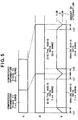
- FIG.5 is a schematic view showing the sound volume control for the digital audio data corresponding to the compressed information stored in the DRAM 7.
- C in FIG.5 shows the compressed information stored in the DRAM 7 by using the linking function.
- C in FIG.5 is equal to (B) in FIG.2.
- D in FIG.5 shows the digital audio data prepared by the fact that the compressed information stored in the DRAM 7 is expanded by the audio information decoder 9.
- E in FIG.5 shows the analog audio data prepared by the fact that the digital audio data shown in (D) is converted by the D/A converter 10.
- the sound volumes thereof have been controlled by the DSP 14.
- the sound volume (attenuator amount) is gradually raised from -C dB to 0 dB, between the beginning of this compressed information piece T1 and the predetermined position tx1. Moreover, in the digital audio data corresponding to the first compressed information piece T1, the sound volume (attenuator amount) is gradually dropped from 0 dB to -C dB, between the predetermined position ty1 and the ending of this compressed information piece T1.
- the sound volume (attenuator amount) is gradually raised from -C dB to 0 dB, between the beginning of this compressed information piece T2 and the predetermined position tx2.
- the sound volume (attenuator amount) is gradually dropped from 0 dB to -C dB, between the predetermined position ty2 and the ending of this compressed information piece T2.
- C is set to an attenuation amount, for example, in such a way that if the MD player 300 is mounted in a car and then the MD 101 is reproduced at a usual sound volume during running, the connection between the reproduction sounds in the boundary between the compressed information pieces is not unnatural and further the driver can recognize these reproduction sounds.
- the compressed information pieces are songs, when a song is ended, a reproduction sound thereof is faded out, and continuously a reproduction sound of the next song is faded in.
- the reproduction sound only decreases to the level corresponding to the above-mentioned predetermined attenuation amount C.
- the songs can be naturally linked, which can prevent the music from being suddenly changed between the songs.
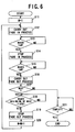
- FIG.6 shows the sound volume control process executed by the DSP 14 and the system controller 17, after the execution of the linking function, in the MD player 300.
- the system controller 17 assigns a value of 1 to a counter M to specify the number of the compressed information piece (step 11). Accordingly, the compressed information corresponding to the first compressed information piece T1 stored in the DRAM 7 by the linking function is read out, and then transferred to the audio information decoder 9. This compressed information is expanded by the audio information decoder 9, and then sent to the DSP 14 as the digital audio data. The system controller 17 controls the DSP 14 to then carry out the fade-in process on this digital audio data (step 12).
- the system controller 17 While this fade-in process is executed, the system controller 17 detects an address corresponding to the compressed information read out from the DRAM 7, and then monitors the progress of the process.
- the system controller 17 determines, on the basis of the address corresponding to the compressed information read out from the DRAM 7, whether or not the digital audio data sent to the DSP 14 reaches a predetermined position tx1 shown in FIG.5 (step 13). If the digital audio data does not reach the position tx1, the system controller 17 continues the fade-in process. On the other hand, if the digital audio data reaches the position tx1, the system controller 17 controls the DSP 14 to thereby stop the fade-in process (step 14).
- the fade-in process is performed on the digital audio data corresponding to the beginning of the first compressed information piece T1, and this is sent to the D/A converter 10.
- the system controller 17 determines, on the basis of the address corresponding to the compressed information read out from the DRAM 7, whether or not the digital audio data sent to the DSP 14 reaches a predetermined position ty1 in FIG.5 (step 15). If the digital audio data does not reach the position ty1, the system controller 17 maintains the attenuation amount of the DSP 14 at 0 dB. Accordingly, the digital audio data is not attenuated. Then, it is passed through the DSP 14, and further sent to the D/A converter 10. On the other hand, if the digital audio data reaches the position ty1, the system controller 17 controls the DSP 14 to thereby carry out the fade-out process on the digital audio data (step 16).
- the system controller 17 determines whether or not the next compressed information piece (the second compressed information piece T2) is stored in the DRAM 7 (step 17). If the second compressed information piece T2 is stored in the DRAM 7, the system controller 17 determines, on the basis of the address corresponding to the compressed information read out from the DRAM 7, whether the digital audio data sent to the DSP 14 reaches a position corresponding to the beginning of the second compressed information piece T2 (step 18). If the digital audio data does not reach the position corresponding to the beginning of the second compressed information piece T2, the system controller 17 continues the fade-out process. On the other hand, if the digital audio data reaches the position corresponding to the beginning of the second compressed information piece T2, the system controller 17 controls the DSP 14 to thereby stop the fade-out process (step 19).
- the fade-out process is performed on the digital audio data corresponding to the ending of the first compressed information piece T1, and this is sent to the D/A converter 10.
- the system controller 17 increases a value of the counter M by 1 (step 21), and then repeats the similar processes. Accordingly, the fade-in process and the fade-out process are performed on the digital audio data corresponding to the second compressed information piece T2. If there is a third compressed information piece, the similar processes are also repeated.
- next compressed information piece T2 is not stored in the DRAM 7 at the step 17, it is determined on the basis of the address corresponding to the compressed information read out from the DRAM 7 whether or not the digital audio data corresponding to the first compressed information piece T1 has been sent to the DSP 14 (step 21). If the digital audio data has not been sent, the system controller 17 continues the fade-out process. On the other hand, if the supply of the digital audio data is ended, the system controller 17 stops the fade-out process. Accordingly, the sound volume control process is ended.
- the fade-in process executed at the steps 12 to 14 is a digital process of gradually raising the attenuation amount of the reproduction sound of the digital audio data from -C dB to 0 dB, between the beginning of the compressed information piece and the predetermined position (for example, tx1), as shown in FIG.5.
- the fade-out process executed at the steps 16 to 19 is a digital process of gradually dropping the sound volume (attenuation amount) from 0 dB to -C dB, between the predetermined position (for example, ty1) and the ending of the compressed information piece.
- the reproduction sound of the digital audio data corresponding to the beginning of each compressed information piece is gradually raised from -C dB to 0 dB, and the reproduction sound of the digital audio data corresponding to the ending of each compressed information piece is gradually dropped from 0 dB to -C dB.
- the combination of the linking function and this sound volume control process enables a plurality of compressed information pieces to be actually linked, by removing the silent portion, the fade-in portion and the fade-out portion between the compressed information pieces, from the compressed information, and further enables the sound volumes of the reproduction sounds at the ending of the compressed information piece and the beginning of the next compressed information piece to be controlled within the range in which the user can recognize the reproduction sound.
- the analog audio signal outputted from the output terminal of the D/A converter 10 is never interrupted even between the compressed information pieces.
- the reproduction sounds are naturally connected between the compressed information pieces.
- the reproduction sound is never suddenly changed between the songs.
- both the fade-in portion and the fade-out portion are removed in the linking function.
- the present invention is not limited to it.
- any one of the fade-in portion and the fade-out portion may be removed.
- the position of the digital audio data sent to the DSP 14 (for example, tx1, ty1) is determined on the basis of the address corresponding to the compressed information read out from the DRAM 7.
- the system controller 17 considers the temporal difference between both the timings to thereby determine the position of the digital audio data to be sent to the DSP 14. Accordingly, the accuracy of the sound volume control process can be improved.
- the attenuation amount C may be fixed or may be properly adjusted by the user. It is not necessary that the change-of the sound volume of the digital audio data corresponding to the beginning of the compressed information piece is a linear change proportional to the time. It is allowable to set a change having a preferable curve (sound volume change performance) depending on a user selection or a song.
- the fade-in process is performed on the digital audio data corresponding to the beginning of the compressed information piece
- the fade-out process is performed on the digital audio data corresponding to the ending of the compressed information piece.
- the present invention is not limited to it. In the sound volume control, only the fade-out process may be performed on the digital audio data corresponding to the ending of the compressed information piece.
- the MD is exemplified as the information record medium
- the MD player is exemplified as the information reproducing apparatus.
- the present invention is not limited to it.
- the present invention can be applied to a CD player, a DVD player and the like which reproduce the information record medium, such as CD, DVD and the like.
- the present invention can be applied to another reproducing apparatus if it is a reproducing apparatus for reproducing a record medium on which a plurality of information pieces can be recorded.
- the case is exemplified in which the information is compressed and recorded on the record medium.
- the present invention is not limited to. the case.
- the present invention can be applied to a reproducing apparatus for reproducing a record medium on which non-compressed information is recorded. This case does not require an information expanding circuit.
Landscapes
- Engineering & Computer Science (AREA)
- Signal Processing (AREA)
- Multimedia (AREA)
- Signal Processing For Digital Recording And Reproducing (AREA)
- Management Or Editing Of Information On Record Carriers (AREA)
- Optical Recording Or Reproduction (AREA)
Applications Claiming Priority (2)
| Application Number | Priority Date | Filing Date | Title |
|---|---|---|---|
| JP1210998 | 1998-01-06 | ||
| JP10012109A JPH11203790A (ja) | 1998-01-06 | 1998-01-06 | 記録媒体情報読取装置 |
Publications (3)
| Publication Number | Publication Date |
|---|---|
| EP0929068A2 true EP0929068A2 (de) | 1999-07-14 |
| EP0929068A3 EP0929068A3 (de) | 1999-10-06 |
| EP0929068B1 EP0929068B1 (de) | 2004-08-11 |
Family
ID=11796406
Family Applications (1)
| Application Number | Title | Priority Date | Filing Date |
|---|---|---|---|
| EP99100014A Expired - Lifetime EP0929068B1 (de) | 1998-01-06 | 1999-01-04 | Gerät zur Wiedergabe einer Vielzahl von Informationsstücken |
Country Status (4)
| Country | Link |
|---|---|
| US (1) | US6807450B1 (de) |
| EP (1) | EP0929068B1 (de) |
| JP (1) | JPH11203790A (de) |
| DE (1) | DE69919236T2 (de) |
Families Citing this family (10)
| Publication number | Priority date | Publication date | Assignee | Title |
|---|---|---|---|---|
| RU2214630C2 (ru) | 1997-07-09 | 2003-10-20 | ЭДВАНСД ОДИО ДИВАЙСИЗ ЭлЭлСи | Оптическое запоминающее устройство |
| JP4595150B2 (ja) * | 1999-12-20 | 2010-12-08 | ソニー株式会社 | 符号化装置および方法、復号装置および方法、並びにプログラム格納媒体 |
| JP2004534274A (ja) * | 2001-03-23 | 2004-11-11 | インスティチュート・フォー・インフォコム・リサーチ | 内容ベースのマルチメディア情報検索で使用するためデジタル表示で音楽情報を表示する方法およびシステム |
| US7386357B2 (en) * | 2002-09-30 | 2008-06-10 | Hewlett-Packard Development Company, L.P. | System and method for generating an audio thumbnail of an audio track |
| CN1754218A (zh) * | 2003-02-26 | 2006-03-29 | 皇家飞利浦电子股份有限公司 | 音频指纹识别中数字静音的处理 |
| US20060235550A1 (en) * | 2003-04-24 | 2006-10-19 | Csicsatka Tibor G | Creation of playlists using audio identification |
| US7596234B2 (en) * | 2003-06-26 | 2009-09-29 | Microsoft Corporation | Method and apparatus for playback of audio files |
| US7522967B2 (en) * | 2003-07-01 | 2009-04-21 | Hewlett-Packard Development Company, L.P. | Audio summary based audio processing |
| US20060059535A1 (en) * | 2004-09-14 | 2006-03-16 | D Avello Robert F | Method and apparatus for playing content |
| US10587667B2 (en) * | 2014-12-30 | 2020-03-10 | Spotify Ab | Location-based tagging and retrieving of media content |
Family Cites Families (11)
| Publication number | Priority date | Publication date | Assignee | Title |
|---|---|---|---|---|
| US3723667A (en) * | 1972-01-03 | 1973-03-27 | Pkm Corp | Apparatus for speech compression |
| JP2672849B2 (ja) * | 1988-12-29 | 1997-11-05 | シャープ株式会社 | ディスク記録再生装置 |
| JPH05145885A (ja) * | 1991-11-22 | 1993-06-11 | Matsushita Electric Ind Co Ltd | 記録再生装置 |
| US5587978A (en) * | 1992-04-16 | 1996-12-24 | Mitsubishi Denki Kabushiki Kaisha | Record/reproduction apparatus for recording/reproducing multi-channel signals in different areas of a recording medium |
| EP0606145B1 (de) * | 1993-01-06 | 2000-03-29 | Sony Corporation | Aufzeichnungsgerät und Aufzeichnungsverfahren für ein Aufzeichnungsmedium |
| JP3517907B2 (ja) * | 1993-10-08 | 2004-04-12 | ソニー株式会社 | ディスク記録装置 |
| US5563866A (en) * | 1993-11-15 | 1996-10-08 | Sony Corporation | Sound editor for editing audio signals by relating new cuts to time-based windows |
| TW332961B (en) * | 1996-02-09 | 1998-06-01 | Sony Co Ltd | Recording media |
| JP3707124B2 (ja) * | 1996-02-22 | 2005-10-19 | ソニー株式会社 | ディスク記録システム及び編集方法 |
| US5995470A (en) * | 1996-04-11 | 1999-11-30 | Sony Corporation | Method of recording and reproducing information signals and apparatus for editing the same |
| JPH10106237A (ja) * | 1996-09-25 | 1998-04-24 | Sony Corp | 編集装置 |
-
1998
- 1998-01-06 JP JP10012109A patent/JPH11203790A/ja active Pending
-
1999
- 1999-01-04 DE DE69919236T patent/DE69919236T2/de not_active Expired - Fee Related
- 1999-01-04 EP EP99100014A patent/EP0929068B1/de not_active Expired - Lifetime
- 1999-01-05 US US09/225,354 patent/US6807450B1/en not_active Expired - Fee Related
Also Published As
| Publication number | Publication date |
|---|---|
| EP0929068A3 (de) | 1999-10-06 |
| JPH11203790A (ja) | 1999-07-30 |
| EP0929068B1 (de) | 2004-08-11 |
| DE69919236D1 (de) | 2004-09-16 |
| US6807450B1 (en) | 2004-10-19 |
| DE69919236T2 (de) | 2005-09-08 |
Similar Documents
| Publication | Publication Date | Title |
|---|---|---|
| JP3199082B2 (ja) | オーディオデータの区切り位置調整方法および装置 | |
| EP0929068B1 (de) | Gerät zur Wiedergabe einer Vielzahl von Informationsstücken | |
| EP0962928B1 (de) | Informationsaufzeichnungsgerät | |
| US5621712A (en) | Reproducing system for an optical recording medium having improved response to a high speed scanning instruction | |
| JP2001155471A (ja) | 記録再生装置 | |
| JP2001155412A (ja) | 再生装置 | |
| US6577563B1 (en) | Disk apparatus | |
| US5655051A (en) | Digital signal reproducing apparatus | |
| JP3839959B2 (ja) | 情報再生装置、情報記録装置、情報再生方法及び情報記録方法 | |
| JP3111144B2 (ja) | 媒体記録再生装置 | |
| EP0413458B1 (de) | Plattenwiedergabegerät | |
| US7801630B2 (en) | Method and apparatus for controlling recording levels | |
| JP3866862B2 (ja) | 情報記録装置及び方法 | |
| JP2001273718A (ja) | 情報再生装置 | |
| JPH10302262A (ja) | 光ディスク再生装置及びその再生方法 | |
| JPH0945003A (ja) | 記録媒体再生装置 | |
| JP3172002B2 (ja) | データの高速ダビング装置および高速ダビング方法 | |
| JPH0828043B2 (ja) | オーディオ機器の再生方法 | |
| JPH09213059A (ja) | ディスク欠陥位置保存方法 | |
| JP3345544B2 (ja) | ピックアップサーボ系の自動調整装置及び調整方法 | |
| JPH11296862A (ja) | ディスク媒体の再生方法 | |
| KR100258592B1 (ko) | 자기기록신호 변환 장치 및 그 방법 | |
| JPH08194982A (ja) | Mdプレーヤ | |
| JPH08293151A (ja) | ダビング装置 | |
| JP2000040348A (ja) | 再生装置 |
Legal Events
| Date | Code | Title | Description |
|---|---|---|---|
| PUAI | Public reference made under article 153(3) epc to a published international application that has entered the european phase |
Free format text: ORIGINAL CODE: 0009012 |
|
| AK | Designated contracting states |
Kind code of ref document: A2 Designated state(s): DE FR GB |
|
| AX | Request for extension of the european patent |
Free format text: AL;LT;LV;MK;RO;SI |
|
| PUAL | Search report despatched |
Free format text: ORIGINAL CODE: 0009013 |
|
| AK | Designated contracting states |
Kind code of ref document: A3 Designated state(s): AT BE CH CY DE DK ES FI FR GB GR IE IT LI LU MC NL PT SE |
|
| AX | Request for extension of the european patent |
Free format text: AL;LT;LV;MK;RO;SI |
|
| 17P | Request for examination filed |
Effective date: 19991026 |
|
| AKX | Designation fees paid |
Free format text: DE FR GB |
|
| 17Q | First examination report despatched |
Effective date: 20021112 |
|
| GRAP | Despatch of communication of intention to grant a patent |
Free format text: ORIGINAL CODE: EPIDOSNIGR1 |
|
| RTI1 | Title (correction) |
Free format text: APPARATUS FOR REPRODUCING A PLURALITY OF INFORMATION PIECES |
|
| GRAS | Grant fee paid |
Free format text: ORIGINAL CODE: EPIDOSNIGR3 |
|
| GRAA | (expected) grant |
Free format text: ORIGINAL CODE: 0009210 |
|
| AK | Designated contracting states |
Kind code of ref document: B1 Designated state(s): DE FR GB |
|
| REG | Reference to a national code |
Ref country code: GB Ref legal event code: FG4D |
|
| REF | Corresponds to: |
Ref document number: 69919236 Country of ref document: DE Date of ref document: 20040916 Kind code of ref document: P |
|
| REG | Reference to a national code |
Ref country code: GB Ref legal event code: 746 Effective date: 20041214 |
|
| PLBE | No opposition filed within time limit |
Free format text: ORIGINAL CODE: 0009261 |
|
| STAA | Information on the status of an ep patent application or granted ep patent |
Free format text: STATUS: NO OPPOSITION FILED WITHIN TIME LIMIT |
|
| ET | Fr: translation filed | ||
| 26N | No opposition filed |
Effective date: 20050512 |
|
| PGFP | Annual fee paid to national office [announced via postgrant information from national office to epo] |
Ref country code: GB Payment date: 20071221 Year of fee payment: 10 |
|
| PGFP | Annual fee paid to national office [announced via postgrant information from national office to epo] |
Ref country code: FR Payment date: 20080125 Year of fee payment: 10 Ref country code: DE Payment date: 20080331 Year of fee payment: 10 |
|
| GBPC | Gb: european patent ceased through non-payment of renewal fee |
Effective date: 20090104 |
|
| PG25 | Lapsed in a contracting state [announced via postgrant information from national office to epo] |
Ref country code: DE Free format text: LAPSE BECAUSE OF NON-PAYMENT OF DUE FEES Effective date: 20090801 |
|
| REG | Reference to a national code |
Ref country code: FR Ref legal event code: ST Effective date: 20091030 |
|
| PG25 | Lapsed in a contracting state [announced via postgrant information from national office to epo] |
Ref country code: GB Free format text: LAPSE BECAUSE OF NON-PAYMENT OF DUE FEES Effective date: 20090104 |
|
| PG25 | Lapsed in a contracting state [announced via postgrant information from national office to epo] |
Ref country code: FR Free format text: LAPSE BECAUSE OF NON-PAYMENT OF DUE FEES Effective date: 20090202 |