EP0928402B1 - Halterung für eine kochfläche - Google Patents
Halterung für eine kochfläche Download PDFInfo
- Publication number
- EP0928402B1 EP0928402B1 EP97943813A EP97943813A EP0928402B1 EP 0928402 B1 EP0928402 B1 EP 0928402B1 EP 97943813 A EP97943813 A EP 97943813A EP 97943813 A EP97943813 A EP 97943813A EP 0928402 B1 EP0928402 B1 EP 0928402B1
- Authority
- EP
- European Patent Office
- Prior art keywords
- frame
- mounting unit
- worktop
- hot plate
- locking
- Prior art date
- Legal status (The legal status is an assumption and is not a legal conclusion. Google has not performed a legal analysis and makes no representation as to the accuracy of the status listed.)
- Expired - Lifetime
Links
Images
Classifications
-
- F—MECHANICAL ENGINEERING; LIGHTING; HEATING; WEAPONS; BLASTING
- F24—HEATING; RANGES; VENTILATING
- F24C—DOMESTIC STOVES OR RANGES ; DETAILS OF DOMESTIC STOVES OR RANGES, OF GENERAL APPLICATION
- F24C15/00—Details
- F24C15/10—Tops, e.g. hot plates; Rings
- F24C15/108—Mounting of hot plate on worktop
-
- A—HUMAN NECESSITIES
- A47—FURNITURE; DOMESTIC ARTICLES OR APPLIANCES; COFFEE MILLS; SPICE MILLS; SUCTION CLEANERS IN GENERAL
- A47B—TABLES; DESKS; OFFICE FURNITURE; CABINETS; DRAWERS; GENERAL DETAILS OF FURNITURE
- A47B77/00—Kitchen cabinets
- A47B77/04—Provision for particular uses of compartments or other parts ; Compartments moving up and down, revolving parts
- A47B77/08—Provision for particular uses of compartments or other parts ; Compartments moving up and down, revolving parts for incorporating apparatus operated by power, including water power; for incorporating apparatus for cooking, cooling, or laundry purposes
Definitions
- the invention relates to a holder for a cooking surface for installation in a Section of a worktop with a frame and a mounting unit, wherein the cooking surface on a support section of the frame or the assembly unit is supported and the frame can be connected to the assembly unit is, wherein the integrally formed frame and the mounting unit each other have assigned locking lugs and locking receptacles over which the frame and the assembly unit can be locked into an assembly
- Such a bracket is known from DE 40 04 093. With this bracket the assembly unit has an outwardly projecting flange which is on the Surface of the worktop is supported. The assembly unit itself is used for Inclusion and shielding of heating elements under the cooking surface are arranged.
- the cooking surface is designed as a glass ceramic plate.
- For Supporting and fixing the cooking surface is the framework described above used. It has a heel with a circumferential horizontal support section on. The edge of the cooking surface can be on the support section applied and firmly fixed here using a silicone adhesive. Snap connections are used to connect the frame to the mounting unit intended.
- the frame legs have a plug receptacle, which from the Support section and a spaced parallel to the support section Cover section is formed.
- the frame legs are with her Push the receptacle onto the edge of the cooking surface.
- the deck section overlaps the top of the hob in the edge area.
- the object of the invention is achieved according to the invention in that the Cooking surface clamped and sealed between the Frame and the assembly unit is held.
- the hob can now be easily connected to the holder become. This is in one assembly step when joining the frame with the Assembly unit possible. Here, the sealing of the Reliable effect cooking surface compared to the bracket.
- the Assembly unit has a receptacle into which the cooking surface is inserted, that the frame carries a web that covers the frame area of the cooking surface, and that the web is in a downward facing, on the cooking surface rising leg passes over.
- the receptacle and the bridge is the Edge area of the cooking surface covered. It is no longer accessible from the outside, so that a risk of injury to the usually made of ceramic glass existing hobs is no longer possible.
- the web on the cooking surface prevents dirt from getting into the Penetrate the area between the surface of the cooking surface and the frame can.
- the web can have, for example, a sealing lip. If the Frame is made in plastic injection molding, then the sealing lip be injected.
- a design variant provides for fixing the holder to the worktop of the invention, a support member on the web of the frame is connected that is placed on the surface of the worktop that the support member keeps the web spaced from the surface of the worktop, and that in the area between the web and the countertop an adhesive layer is introduced.
- the web and the support part thus create a receiving space for the adhesive layer.
- the adhesive layer can also act as a sealing element serve.
- the locking of the frame with the assembly unit is thereby, for example possible that the frame has a detent provided with a deflection carries that the mounting unit at a distance from the worktop has running edge, and that the locking approach by the between the Worktop and the edge formed space passed through and at one trained as an undercut latching snap locked behind the edge is.
- the assembly unit can form an assembly together with the frame be pre-assembled and then inserted into the cutout of the worktop become. It can be provided that the distance between the latching approach to the worktop is less than that required for locking Deflection distance. This means that the catch can no longer be released automatically, when the bracket is mounted in the cutout.
- the frame has a receptacle into which the cooking surface is inserted, and that the Assembly unit by means of the locking lugs and the locking receptacles with the Frame can be locked.
- the cooking surface can then be used first be connected to the frame.
- the assembly unit is then attached to the The frame snapped in and the bracket thus formed was installed in the worktop.
- a holder designed according to the invention can be characterized in that that the mounting unit has fasteners, which are located on springs Support heating elements, and that in the locked state of the frame with the Mounting unit pressed the heating elements on the underside of the cooking surface and the springs are deflected.
- the heating elements can therefore in the assembly unit be used. Then the hob can be placed on the Place heating elements. Then when the frame is connected to the assembly unit the cooking surface is moved. This also deflects the springs.
- the heating elements are adequately fixed and pressed on the underside of the cooking surface.
- the frame and the assembly unit can be made of thermosetting or thermoplastic or plastic composite material. Any material pairings are possible.
- the Frame made of a thermoset the holder made of a thermoplastic consist.
- a material that is scratch-resistant, temperature-resistant, is food safe and colourfast.
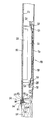
- the drawing shows a side view and in section a part of a worktop 10 which is provided with a cutout is.
- a bracket is inserted in the cutout.
- the bracket is there essentially of a frame 30 and an assembly unit 40.
- the mounting unit 40 is trough-shaped and has a base unit 47 and a peripheral wall 43 connected to it.
- the floor assembly 47 carries fasteners 48, which are in the interior of the mounting unit 40 project.
- Springs 50 are fastened to the fastening parts 48.
- the Springs 50 have fastening sections 52 which are connected to the fastening parts 48 are connected.
- the springs 50 have a support section 51 provided. This support section 51 engages under a receiving body 61. In one or more heating elements 60 can be used in the receiving body 61 his. Depending on the size of the receiving body 61 there are several springs 50 connected to the floor assembly 47.
- the heating elements 60 are with the springs 50 on the underside of a cooking surface 20 pressed.
- the cooking surface 20 can be used, for example, as a glass ceramic hob be trained.
- the cooking surface 20 is located in its edge region with a support section 23 on an outwardly directed flange of the assembly unit 40 on.
- the flange is angled vertically outward from wall 43. He ends in an edge 41.
- the flange and the wall 43 together form one Holder for the edge of the cooking surface 20.
- a seal 35 is used, which is located on the underside, the side and the Top of the cooking surface 20 creates.
- a silicone adhesive may be used for sealing the cooking surface 20 pressed.
- the frame 30 is essentially T-shaped in cross section and made in one piece from a plastic.
- the frame 30 has a horizontal web 32, which over the top of the cooking surface 20 and Worktop 10 protrudes.
- a latching attachment 34 adjoins the web 32.
- the locking projection 34 is between the worktop 10 and the edge 41 passed and locked to an undercut of the flange, which as Locking receptacle 42 is formed.
- Locking receptacle 42 is formed.
- a downward support member 36 that stands up on the top of the worktop 10.
- the support member 36 holds the web 32 spaced from the worktop 10. This creates a space between the worktop 10 and the web 32. In this space there is an adhesive layer brought in.
- the adhesive layer connects the worktop 10 to the holder.
- leg 33 At the end of the web 32 facing the cooking surface 20 is a leg 33 molded.
- This leg 33 stands on the top of the cooking surface 20 on.
- the leg 33 keeps the web 32 spaced from the top of the cooking surface 20. This again creates a receiving space for the seal 35.
- the leg 33 itself can have a sealing function in a corresponding configuration take. For example, it is possible that it is in a sealing lip runs out, which creates on the cooking surface 20. However, it is also possible to Form leg 33 from a soft plastic. In this case, he can be molded onto the web 32.
- the assembly unit 40 is first with the Heating elements 60 equipped. Then the cooking surface 20 is on the Heating elements 60 placed. Then the frame 30 can be snapped on. The Cooking surface 20 is in the receptacle provided for it in the Mounting unit pressed in. The formed from frame 30 and assembly unit 40 Unit can be inserted as a part in the cutout of worktop 10 and be fixed via the adhesive 31.
Landscapes
- Engineering & Computer Science (AREA)
- Sustainable Development (AREA)
- Chemical & Material Sciences (AREA)
- Combustion & Propulsion (AREA)
- Mechanical Engineering (AREA)
- General Engineering & Computer Science (AREA)
- Life Sciences & Earth Sciences (AREA)
- Induction Heating Cooking Devices (AREA)
- Cookers (AREA)
- Baking, Grill, Roasting (AREA)
- Electric Stoves And Ranges (AREA)
- Furniture Connections (AREA)
- Other Liquid Machine Or Engine Such As Wave Power Use (AREA)
- Fuel Cell (AREA)
- Adornments (AREA)
- Resistance Heating (AREA)
- Combinations Of Kitchen Furniture (AREA)
Description
Claims (7)
- Halterung für eine Kochfläche zum Einbau in einen Ausschnitt einer Arbeitsplatte mit einem Rahmen und einer Montageeinheit, wobei die Kochfläche an einem Stützabschnitt des Rahmens oder der Montageeinheit abgestützt ist und wobei der Rahmen mit der Montageeinheit verbindbar ist, und wobei der einstückig ausgebildete Rahmen und die Montageeinheit einander zugeordnete Rastansätze und Rastaufnahmen aufweisen, über die der Rahmen und die Montageeinheit zu einer Baugruppe verrastbar sind,
dadurch gekennzeichnet,
daß die Kochfläche (20) über die Rastverbindung verspannt und abgedichtet zwischen dem Rahmen (30) und der Montageeinheit (40) gehalten ist. - Halterung nach Anspruch 1,
dadurch gekennzeichnet,daß die Montageeinheit (40) eine Aufnahme aufweist, in die die Kochfläche (20) eingesetzt ist, daß der Rahmen (30) einen Steg (32) trägt, der den Randbereich der Kochfläche (20) überdeckt, unddaß der Steg (32) in einen abwärts gerichteten, auf der Kochfläche (20) aufstehenden Schenkel (33) übergeht. - Halterung nach Anspruch 2,
dadurch gekennzeichnet,daß an dem Steg (32) des Rahmens (30) ein Stützteil (36) angeschlossen ist, das auf der Oberfläche der Arbeitsplatte (10) aufgesetzt ist,daß das Stützteil (36) den Steg (32) beabstandet zu der Oberfläche der Arbeitsplatte (10) hält, unddaß im Bereich zwischen dem Steg (32) und der Arbeitsplatte (10) eine Klebschicht eingebracht ist. - Halterung nach einem der Ansprüche 1 bis 3,
dadurch gekennzeichnet,daß der Rahmen (30) den mit einer Auslenkschräge versehenen Rastansatz (42) trägt,daß die Montageeinheit (40) einen im Abstand zu der Arbeitsplatte (10) verlaufenden Rand (41) hat, unddaß der Rastansatz (34) durch den zwischen der Arbeitsplatte (10) und dem Rand (41) gebildeten Freiraum hindurch geführt und an einer als Hinterschneidung ausgebildeten Rastaufnahme (42) hinter dem Rand (41) verrastet ist. - Halterung nach Anspruch 1,
dadurch gekennzeichnet,daß der Rahmen (30) eine Aufnahme aufweist, in die die Kochfläche (20) eingesetzt ist, unddaß die Montageeinheit (40) mittels der Rastansätze (34) und der Rastaufnahmen (42) mit dem Rahmen (30) verrastbar ist. - Halterung nach einem der Ansprüche 1 bis 5,
dadurch gekennzeichnet,daß die Montageeinheit (40) Befestigungsteile (48) aufweist, an denen sich über Federn (50) Heizelemente (60) abstützen, unddaß im verrasteten Zustand des Rahmens mit der Montageeinheit (40) die Heizelemente (60) an der Unterseite (22) der Kochfläche (20) angepreßt und die Federn (50) ausgelenkt sind. - Halterung nach einem der Ansprüche 1 bis 6,
dadurch gekennzeichnet,
daß der Rahmen (30) und die Montageeinheit (40) aus duroplastischem oder thermoplastischem Kunststoff- oder Kunststoff-Verbundwerkstoffen gefertigt sind.
Applications Claiming Priority (3)
| Application Number | Priority Date | Filing Date | Title |
|---|---|---|---|
| DE19637784 | 1996-09-17 | ||
| DE19637784A DE19637784C1 (de) | 1996-09-17 | 1996-09-17 | Halterung für eine Kochfläche |
| PCT/EP1997/004507 WO1998012482A1 (de) | 1996-09-17 | 1997-08-18 | Halterung für eine kochfläche |
Publications (2)
| Publication Number | Publication Date |
|---|---|
| EP0928402A1 EP0928402A1 (de) | 1999-07-14 |
| EP0928402B1 true EP0928402B1 (de) | 2000-10-11 |
Family
ID=7805832
Family Applications (1)
| Application Number | Title | Priority Date | Filing Date |
|---|---|---|---|
| EP97943813A Expired - Lifetime EP0928402B1 (de) | 1996-09-17 | 1997-08-18 | Halterung für eine kochfläche |
Country Status (10)
| Country | Link |
|---|---|
| US (1) | US6175102B1 (de) |
| EP (1) | EP0928402B1 (de) |
| JP (1) | JP2001503128A (de) |
| AT (1) | ATE196945T1 (de) |
| BR (1) | BR9712066A (de) |
| CA (1) | CA2304067A1 (de) |
| DE (2) | DE19637784C1 (de) |
| ES (1) | ES2151745T3 (de) |
| PL (1) | PL184123B1 (de) |
| WO (1) | WO1998012482A1 (de) |
Cited By (1)
| Publication number | Priority date | Publication date | Assignee | Title |
|---|---|---|---|---|
| CN107435956A (zh) * | 2016-05-26 | 2017-12-05 | 博西华电器(江苏)有限公司 | 灶台总成及用于灶台总成的灶具和包边 |
Families Citing this family (16)
| Publication number | Priority date | Publication date | Assignee | Title |
|---|---|---|---|---|
| US6635853B2 (en) * | 1909-08-09 | 2003-10-21 | Ibiden Co., Ltd. | Hot plate unit |
| DE19642020C2 (de) * | 1996-10-11 | 1999-05-20 | Bosch Siemens Hausgeraete | Abstandshalter für Kochfeldplatten |
| FR2783596B1 (fr) * | 1998-09-23 | 2001-03-09 | Eurokera | Ensemble prefabrique destine a la realisation de tables de cuisson |
| DE19854229B4 (de) * | 1998-11-24 | 2011-07-28 | BSH Bosch und Siemens Hausgeräte GmbH, 81739 | Kochfeld mit zweiteiligem Rahmen |
| AU2001287186A1 (en) | 2000-08-18 | 2002-03-04 | Luxine Inc. | Induction heating and control system and method with high reliability and advanced performance features |
| DE10207515B4 (de) * | 2002-02-22 | 2004-12-02 | Schott Ag | Kochsystem mit einer Kochfläche und einer Halterung |
| DE10341847B4 (de) * | 2003-09-09 | 2007-12-27 | Miele & Cie. Kg | Einbaukochmulde |
| EP1818619B1 (de) * | 2004-11-10 | 2017-06-21 | Panasonic Corporation | Eingebaute kochvorrichtung und küchen-arbeitsfläche, in die die kochvorrichtung eingebaut ist |
| US20060289489A1 (en) * | 2005-05-09 | 2006-12-28 | Dongyu Wang | Induction cooktop with remote power electronics |
| FR2889580B1 (fr) * | 2005-08-02 | 2013-11-22 | Eurokera | Plaque de cuisson, appareil de cuisson et procede de fabrication de la plaque |
| JP4710483B2 (ja) * | 2005-08-19 | 2011-06-29 | パナソニック株式会社 | 調理器 |
| US20070044788A1 (en) * | 2005-08-26 | 2007-03-01 | Wacker Chemical Corporation | Method for mounting ceramic cooktops in appliance |
| US20080145595A1 (en) * | 2006-12-14 | 2008-06-19 | Pratt Charles F | Composite pedestal base assembly |
| WO2013075971A1 (de) * | 2011-11-23 | 2013-05-30 | BSH Bosch und Siemens Hausgeräte GmbH | Zierrahmen für ein haushaltsgerät, haushaltsgerät mit einem derartigen zierrahmen und verfahren zum herstellen eines zierrahmens |
| KR101692636B1 (ko) | 2015-09-02 | 2017-01-03 | 엘지전자 주식회사 | 가스켓이 구비된 조리기기 |
| FR3089280A1 (fr) * | 2018-11-30 | 2020-06-05 | Eurokera S.N.C | Article vitroceramique |
Family Cites Families (10)
| Publication number | Priority date | Publication date | Assignee | Title |
|---|---|---|---|---|
| US3866018A (en) * | 1974-04-01 | 1975-02-11 | Gen Electric | Molded plastic cooktop with heated glass-ceramic plate insert |
| GB2090399B (en) * | 1980-11-04 | 1984-02-22 | Belling & Co Ltd | Hob assembly |
| DE3104114C2 (de) | 1981-02-06 | 1984-06-14 | Schott Glaswerke, 6500 Mainz | Halterung für eine Platte aus Glas, Glaskeramik oder ähnlichem Material, insbesondere für eine Kochfläche |
| DE3337148A1 (de) * | 1983-10-12 | 1985-04-25 | Bosch-Siemens Hausgeräte GmbH, 7000 Stuttgart | Kochmulde |
| DE8624136U1 (de) * | 1985-10-23 | 1986-11-06 | N.V. Philips' Gloeilampenfabrieken, Eindhoven | Kochmulde zum Einbau in Einbauküchen |
| EP0391122A3 (de) * | 1989-04-04 | 1991-07-31 | Elektra Bregenz Aktiengesellschaft | Montageprofilleiste für Glaskeramikkochfelder |
| DE4004093C2 (de) * | 1990-02-10 | 1994-10-27 | Miele & Cie | Einbau-Kochfeld mit einer Glaskeramik-Kochfläche |
| DE4329956C2 (de) * | 1993-09-04 | 1996-08-14 | Schott Glaswerke | Anordnung zur Halterung eines Einbaukochfeldes |
| DE19521690A1 (de) * | 1995-06-14 | 1996-12-19 | Bosch Siemens Hausgeraete | Glaskeramikmulde |
| US5841109A (en) * | 1997-04-07 | 1998-11-24 | General Electric Company | Glass supported heating elements for radiant cooktop ranges |
-
1996
- 1996-09-17 DE DE19637784A patent/DE19637784C1/de not_active Expired - Fee Related
-
1997
- 1997-08-18 PL PL97332289A patent/PL184123B1/pl not_active IP Right Cessation
- 1997-08-18 EP EP97943813A patent/EP0928402B1/de not_active Expired - Lifetime
- 1997-08-18 BR BR9712066-9A patent/BR9712066A/pt not_active Application Discontinuation
- 1997-08-18 WO PCT/EP1997/004507 patent/WO1998012482A1/de not_active Ceased
- 1997-08-18 ES ES97943813T patent/ES2151745T3/es not_active Expired - Lifetime
- 1997-08-18 JP JP10514036A patent/JP2001503128A/ja active Pending
- 1997-08-18 DE DE59702469T patent/DE59702469D1/de not_active Expired - Fee Related
- 1997-08-18 AT AT97943813T patent/ATE196945T1/de not_active IP Right Cessation
- 1997-08-18 US US09/147,869 patent/US6175102B1/en not_active Expired - Fee Related
- 1997-08-18 CA CA002304067A patent/CA2304067A1/en not_active Abandoned
Cited By (1)
| Publication number | Priority date | Publication date | Assignee | Title |
|---|---|---|---|---|
| CN107435956A (zh) * | 2016-05-26 | 2017-12-05 | 博西华电器(江苏)有限公司 | 灶台总成及用于灶台总成的灶具和包边 |
Also Published As
| Publication number | Publication date |
|---|---|
| DE19637784C1 (de) | 1997-10-16 |
| US6175102B1 (en) | 2001-01-16 |
| DE59702469D1 (de) | 2000-11-16 |
| WO1998012482A1 (de) | 1998-03-26 |
| ES2151745T3 (es) | 2001-01-01 |
| PL184123B1 (pl) | 2002-09-30 |
| ATE196945T1 (de) | 2000-10-15 |
| BR9712066A (pt) | 2000-01-18 |
| EP0928402A1 (de) | 1999-07-14 |
| CA2304067A1 (en) | 1998-03-26 |
| PL332289A1 (en) | 1999-08-30 |
| JP2001503128A (ja) | 2001-03-06 |
Similar Documents
| Publication | Publication Date | Title |
|---|---|---|
| DE19637784C1 (de) | Halterung für eine Kochfläche | |
| EP0059824B1 (de) | Polsterkörper für den Innenraum von Fahrzeugen, insbesondere Armlehne | |
| DE4210010A1 (de) | Kochmulde | |
| DE3009961A1 (de) | Glaskeramik-kochfeldeinheit zum einbau in eine arbeitsplatte | |
| DE19637896C1 (de) | Halterung für eine Kochfläche | |
| EP0767520B1 (de) | Filterlüfter | |
| DE102009045665B4 (de) | Bedieneinrichtung für ein Haushaltsgerät sowie Haushaltsgerät mit einer derartigen Bedieneinrichtung | |
| DE3712718A1 (de) | Wandanschlussleiste fuer kuechenschraenke, arbeitsplatten von einbaukuechen oder dgl. | |
| DE19845011A1 (de) | Seitenverkleidung für einen höhenverstellbaren Fahrzeugsitz | |
| DE3820334C1 (en) | Arrangement for mounting a sun visor in a vehicle | |
| DE3420532C3 (de) | Flächenbündig einbaubarer Einsatz für Küchen-Tischplatten | |
| AT401851B (de) | Beschlag | |
| EP3561391A1 (de) | Rahmenvorrichtung für ein kochfeldsystem | |
| EP0958476A1 (de) | Halterung für eine kochfläche | |
| DE19703270C2 (de) | Halterung für eine Kochfläche | |
| DE3015251C2 (de) | ||
| DE2647156B2 (de) | Einbaukochgerät | |
| AT14566U1 (de) | Möbelkomponente eines Möbels | |
| DE9422457U1 (de) | Beschlag zur Befestigung einer Rückwand einer Schublade | |
| EP1366644A1 (de) | Arbeitsplattenanordnung | |
| EP0839346A1 (de) | Vorrichtung zum anbringen eines bedienfeldes an die vordere unterkante eines steuergerätes | |
| DE19721776C2 (de) | Tragteil für eine Kochfläche | |
| DE3516546C2 (de) | Anschlußeinrichtung für eine Verkleidungsplatte an einer vertikalen Nischenrückwand im Möbelbau | |
| DE10013007C2 (de) | Schaltschrank | |
| DE9301942U1 (de) | Einbaukochfeld |
Legal Events
| Date | Code | Title | Description |
|---|---|---|---|
| PUAI | Public reference made under article 153(3) epc to a published international application that has entered the european phase |
Free format text: ORIGINAL CODE: 0009012 |
|
| 17P | Request for examination filed |
Effective date: 19990419 |
|
| AK | Designated contracting states |
Kind code of ref document: A1 Designated state(s): AT BE CH DE DK ES FR GB IT LI LU NL SE |
|
| RAP1 | Party data changed (applicant data changed or rights of an application transferred) |
Owner name: LKH-KUNSTSTOFFWERK GMBH & CO. KG Owner name: SCHOTT GLAS |
|
| GRAG | Despatch of communication of intention to grant |
Free format text: ORIGINAL CODE: EPIDOS AGRA |
|
| GRAG | Despatch of communication of intention to grant |
Free format text: ORIGINAL CODE: EPIDOS AGRA |
|
| GRAH | Despatch of communication of intention to grant a patent |
Free format text: ORIGINAL CODE: EPIDOS IGRA |
|
| 17Q | First examination report despatched |
Effective date: 20000202 |
|
| GRAH | Despatch of communication of intention to grant a patent |
Free format text: ORIGINAL CODE: EPIDOS IGRA |
|
| GRAA | (expected) grant |
Free format text: ORIGINAL CODE: 0009210 |
|
| AK | Designated contracting states |
Kind code of ref document: B1 Designated state(s): AT BE CH DE DK ES FR GB IT LI LU NL SE |
|
| PG25 | Lapsed in a contracting state [announced via postgrant information from national office to epo] |
Ref country code: NL Free format text: LAPSE BECAUSE OF FAILURE TO SUBMIT A TRANSLATION OF THE DESCRIPTION OR TO PAY THE FEE WITHIN THE PRESCRIBED TIME-LIMIT Effective date: 20001011 |
|
| REF | Corresponds to: |
Ref document number: 196945 Country of ref document: AT Date of ref document: 20001015 Kind code of ref document: T |
|
| ITF | It: translation for a ep patent filed | ||
| REG | Reference to a national code |
Ref country code: CH Ref legal event code: EP |
|
| REF | Corresponds to: |
Ref document number: 59702469 Country of ref document: DE Date of ref document: 20001116 |
|
| REG | Reference to a national code |
Ref country code: ES Ref legal event code: FG2A Ref document number: 2151745 Country of ref document: ES Kind code of ref document: T3 |
|
| PG25 | Lapsed in a contracting state [announced via postgrant information from national office to epo] |
Ref country code: SE Free format text: LAPSE BECAUSE OF FAILURE TO SUBMIT A TRANSLATION OF THE DESCRIPTION OR TO PAY THE FEE WITHIN THE PRESCRIBED TIME-LIMIT Effective date: 20010111 Ref country code: DK Free format text: LAPSE BECAUSE OF FAILURE TO SUBMIT A TRANSLATION OF THE DESCRIPTION OR TO PAY THE FEE WITHIN THE PRESCRIBED TIME-LIMIT Effective date: 20010111 |
|
| GBT | Gb: translation of ep patent filed (gb section 77(6)(a)/1977) |
Effective date: 20010105 |
|
| ET | Fr: translation filed | ||
| NLV1 | Nl: lapsed or annulled due to failure to fulfill the requirements of art. 29p and 29m of the patents act | ||
| PLBE | No opposition filed within time limit |
Free format text: ORIGINAL CODE: 0009261 |
|
| STAA | Information on the status of an ep patent application or granted ep patent |
Free format text: STATUS: NO OPPOSITION FILED WITHIN TIME LIMIT |
|
| PG25 | Lapsed in a contracting state [announced via postgrant information from national office to epo] |
Ref country code: LU Free format text: LAPSE BECAUSE OF NON-PAYMENT OF DUE FEES Effective date: 20010818 |
|
| PG25 | Lapsed in a contracting state [announced via postgrant information from national office to epo] |
Ref country code: LI Free format text: LAPSE BECAUSE OF NON-PAYMENT OF DUE FEES Effective date: 20010831 Ref country code: CH Free format text: LAPSE BECAUSE OF NON-PAYMENT OF DUE FEES Effective date: 20010831 Ref country code: BE Free format text: LAPSE BECAUSE OF NON-PAYMENT OF DUE FEES Effective date: 20010831 |
|
| 26N | No opposition filed | ||
| REG | Reference to a national code |
Ref country code: GB Ref legal event code: IF02 |
|
| BERE | Be: lapsed |
Owner name: LKH-KUNSTSTOFFWERK G.M.B.H. & CO. K.G. Effective date: 20010831 Owner name: SCHOTT GLAS Effective date: 20010831 |
|
| REG | Reference to a national code |
Ref country code: CH Ref legal event code: PL |
|
| PGFP | Annual fee paid to national office [announced via postgrant information from national office to epo] |
Ref country code: GB Payment date: 20040730 Year of fee payment: 8 |
|
| PGFP | Annual fee paid to national office [announced via postgrant information from national office to epo] |
Ref country code: AT Payment date: 20040810 Year of fee payment: 8 |
|
| PGFP | Annual fee paid to national office [announced via postgrant information from national office to epo] |
Ref country code: ES Payment date: 20040819 Year of fee payment: 8 |
|
| PGFP | Annual fee paid to national office [announced via postgrant information from national office to epo] |
Ref country code: FR Payment date: 20050812 Year of fee payment: 9 Ref country code: DE Payment date: 20050812 Year of fee payment: 9 |
|
| PG25 | Lapsed in a contracting state [announced via postgrant information from national office to epo] |
Ref country code: IT Free format text: LAPSE BECAUSE OF NON-PAYMENT OF DUE FEES Effective date: 20050818 Ref country code: AT Free format text: LAPSE BECAUSE OF NON-PAYMENT OF DUE FEES Effective date: 20050818 |
|
| PG25 | Lapsed in a contracting state [announced via postgrant information from national office to epo] |
Ref country code: ES Free format text: LAPSE BECAUSE OF NON-PAYMENT OF DUE FEES Effective date: 20050819 |
|
| GBPC | Gb: european patent ceased through non-payment of renewal fee |
Effective date: 20050818 |
|
| REG | Reference to a national code |
Ref country code: ES Ref legal event code: FD2A Effective date: 20050819 |
|
| PG25 | Lapsed in a contracting state [announced via postgrant information from national office to epo] |
Ref country code: DE Free format text: LAPSE BECAUSE OF NON-PAYMENT OF DUE FEES Effective date: 20070301 |
|
| REG | Reference to a national code |
Ref country code: FR Ref legal event code: ST Effective date: 20070430 |
|
| PG25 | Lapsed in a contracting state [announced via postgrant information from national office to epo] |
Ref country code: FR Free format text: LAPSE BECAUSE OF NON-PAYMENT OF DUE FEES Effective date: 20060831 |