EP0926662B1 - Dispositif à disque optique - Google Patents
Dispositif à disque optique Download PDFInfo
- Publication number
- EP0926662B1 EP0926662B1 EP98123460A EP98123460A EP0926662B1 EP 0926662 B1 EP0926662 B1 EP 0926662B1 EP 98123460 A EP98123460 A EP 98123460A EP 98123460 A EP98123460 A EP 98123460A EP 0926662 B1 EP0926662 B1 EP 0926662B1
- Authority
- EP
- European Patent Office
- Prior art keywords
- optical disc
- amplitude
- light beam
- signal
- information
- Prior art date
- Legal status (The legal status is an assumption and is not a legal conclusion. Google has not performed a legal analysis and makes no representation as to the accuracy of the status listed.)
- Expired - Lifetime
Links
- 230000003287 optical effect Effects 0.000 title claims description 338
- 230000008859 change Effects 0.000 claims description 20
- 230000004044 response Effects 0.000 claims description 9
- 230000007935 neutral effect Effects 0.000 claims description 7
- 238000000034 method Methods 0.000 description 20
- 239000003990 capacitor Substances 0.000 description 19
- 239000011295 pitch Substances 0.000 description 19
- 230000007423 decrease Effects 0.000 description 17
- 230000000052 comparative effect Effects 0.000 description 12
- 238000010586 diagram Methods 0.000 description 12
- 230000008569 process Effects 0.000 description 11
- 230000035945 sensitivity Effects 0.000 description 8
- 238000002310 reflectometry Methods 0.000 description 7
- 230000008901 benefit Effects 0.000 description 5
- 230000008878 coupling Effects 0.000 description 4
- 238000010168 coupling process Methods 0.000 description 4
- 238000005859 coupling reaction Methods 0.000 description 4
- 238000001514 detection method Methods 0.000 description 4
- 238000006073 displacement reaction Methods 0.000 description 4
- 230000000704 physical effect Effects 0.000 description 4
- 230000003321 amplification Effects 0.000 description 3
- 238000003199 nucleic acid amplification method Methods 0.000 description 3
- 238000004904 shortening Methods 0.000 description 3
- 230000000694 effects Effects 0.000 description 2
- 230000010349 pulsation Effects 0.000 description 2
- 230000003252 repetitive effect Effects 0.000 description 2
- 238000007796 conventional method Methods 0.000 description 1
- 230000003247 decreasing effect Effects 0.000 description 1
- 230000009189 diving Effects 0.000 description 1
- 239000000284 extract Substances 0.000 description 1
- 230000010354 integration Effects 0.000 description 1
- 239000011159 matrix material Substances 0.000 description 1
- 230000007246 mechanism Effects 0.000 description 1
Images


Classifications
-
- G—PHYSICS
- G11—INFORMATION STORAGE
- G11B—INFORMATION STORAGE BASED ON RELATIVE MOVEMENT BETWEEN RECORD CARRIER AND TRANSDUCER
- G11B19/00—Driving, starting, stopping record carriers not specifically of filamentary or web form, or of supports therefor; Control thereof; Control of operating function ; Driving both disc and head
- G11B19/20—Driving; Starting; Stopping; Control thereof
-
- G—PHYSICS
- G11—INFORMATION STORAGE
- G11B—INFORMATION STORAGE BASED ON RELATIVE MOVEMENT BETWEEN RECORD CARRIER AND TRANSDUCER
- G11B19/00—Driving, starting, stopping record carriers not specifically of filamentary or web form, or of supports therefor; Control thereof; Control of operating function ; Driving both disc and head
- G11B19/02—Control of operating function, e.g. switching from recording to reproducing
- G11B19/12—Control of operating function, e.g. switching from recording to reproducing by sensing distinguishing features of or on records, e.g. diameter end mark
- G11B19/128—Control of operating function, e.g. switching from recording to reproducing by sensing distinguishing features of or on records, e.g. diameter end mark involving the detection of track pitch or recording density
-
- G—PHYSICS
- G11—INFORMATION STORAGE
- G11B—INFORMATION STORAGE BASED ON RELATIVE MOVEMENT BETWEEN RECORD CARRIER AND TRANSDUCER
- G11B19/00—Driving, starting, stopping record carriers not specifically of filamentary or web form, or of supports therefor; Control thereof; Control of operating function ; Driving both disc and head
- G11B19/02—Control of operating function, e.g. switching from recording to reproducing
- G11B19/12—Control of operating function, e.g. switching from recording to reproducing by sensing distinguishing features of or on records, e.g. diameter end mark
-
- G—PHYSICS
- G11—INFORMATION STORAGE
- G11B—INFORMATION STORAGE BASED ON RELATIVE MOVEMENT BETWEEN RECORD CARRIER AND TRANSDUCER
- G11B7/00—Recording or reproducing by optical means, e.g. recording using a thermal beam of optical radiation by modifying optical properties or the physical structure, reproducing using an optical beam at lower power by sensing optical properties; Record carriers therefor
- G11B7/08—Disposition or mounting of heads or light sources relatively to record carriers
- G11B7/085—Disposition or mounting of heads or light sources relatively to record carriers with provision for moving the light beam into, or out of, its operative position or across tracks, otherwise than during the transducing operation, e.g. for adjustment or preliminary positioning or track change or selection
-
- G—PHYSICS
- G11—INFORMATION STORAGE
- G11B—INFORMATION STORAGE BASED ON RELATIVE MOVEMENT BETWEEN RECORD CARRIER AND TRANSDUCER
- G11B7/00—Recording or reproducing by optical means, e.g. recording using a thermal beam of optical radiation by modifying optical properties or the physical structure, reproducing using an optical beam at lower power by sensing optical properties; Record carriers therefor
- G11B7/08—Disposition or mounting of heads or light sources relatively to record carriers
- G11B7/09—Disposition or mounting of heads or light sources relatively to record carriers with provision for moving the light beam or focus plane for the purpose of maintaining alignment of the light beam relative to the record carrier during transducing operation, e.g. to compensate for surface irregularities of the latter or for track following
- G11B7/0946—Disposition or mounting of heads or light sources relatively to record carriers with provision for moving the light beam or focus plane for the purpose of maintaining alignment of the light beam relative to the record carrier during transducing operation, e.g. to compensate for surface irregularities of the latter or for track following specially adapted for operation during external perturbations not related to the carrier or servo beam, e.g. vibration
-
- G—PHYSICS
- G11—INFORMATION STORAGE
- G11B—INFORMATION STORAGE BASED ON RELATIVE MOVEMENT BETWEEN RECORD CARRIER AND TRANSDUCER
- G11B7/00—Recording or reproducing by optical means, e.g. recording using a thermal beam of optical radiation by modifying optical properties or the physical structure, reproducing using an optical beam at lower power by sensing optical properties; Record carriers therefor
- G11B2007/0003—Recording, reproducing or erasing systems characterised by the structure or type of the carrier
- G11B2007/0006—Recording, reproducing or erasing systems characterised by the structure or type of the carrier adapted for scanning different types of carrier, e.g. CD & DVD
-
- G—PHYSICS
- G11—INFORMATION STORAGE
- G11B—INFORMATION STORAGE BASED ON RELATIVE MOVEMENT BETWEEN RECORD CARRIER AND TRANSDUCER
- G11B2220/00—Record carriers by type
- G11B2220/20—Disc-shaped record carriers
- G11B2220/25—Disc-shaped record carriers characterised in that the disc is based on a specific recording technology
- G11B2220/2537—Optical discs
Definitions
- the present invention relates to an optical disc device in accordance with the precharacterizing parts of independent claims 1 and 2, said optical disc device being capable of easily identifying the types of the discs in a short time.
- An optical disc device of this type is known from US-A-5,684,773.
- Japanese laid-open publication (Tokukaihei) No. 3-207056 discloses a method of identifying the types of discs for an optical disc device using various types of optical discs.
- specific information signals (type identifying signals) recorded on the respective optical discs in advance are read out so as to identify various types of optical discs, more specifically distinguish a music-use CD (compact disc) and a computer-use CD-ROM.
- an optical disc device using various types of discs for example, CD and DVD (digital video disc), which are different from each other in their physical properties, particularly in the recording density and track pitch, to a greater degree than the degree of the differences between the music-use CD and the computer-use CD-ROM, it is often necessary to perform the process of switching an optical system of an optical pickup in order to obtain better signal reproduction characteristics in some cases.
- the above-mentioned processes can only be carried out after identifying the type of the disc. As a result, it takes a long time to start the optical disc device.
- the optical disc device known from US-A-5,684,773 which is corresponding to precharacterizing parts of the independent claims 1 and 2 includes a disc discriminating circuit for discriminating the kind of optical discs on the basis of amplitude levels of the supplied read signals, TOC data and others.
- said document does not disclose to discriminate the kind of disc based on a change in an amplitude of a readout signal.
- an amplitude of the RF signal is used by the amplitude indicating signal generating means of the known optical disc device, an amplitude of modulated data having minimum inversion intervals of 3T is detected, and the higher the recording density is (DVD has a higher recording density than CD-discs), the smaller the amplitude is.
- EP-A-0 881 638 being prior art according to Art.
- 54(3) EPC discloses an optical disc discriminating apparatus which uses a 3-beam-system for judging the type of the optical disc and a comparison between an amplitude of a tracking error signal and a reference amplitude or a comparison between a phase difference between the detection value of subbeams. Said subbeams are produced by an optical pickup for tracking servo control.
- An optical disc recording apparatus which is disclosed in EP-A-0 453 995 is constructed to detect whether an RF-signal is present or absent in a recordable disc and to automatically determine if the optical disc is an unrecorded or a prerecorded disc based on the detection to inhibit recording of information on a prerecorded optical disc.
- a peak holding and a bottom holding means are provided and supplied by the reproduced RF-signals from a matrix circuit.
- the peak holding circuit holds a peak value of the reproduced RF-signals and the bottom holding circuit holds a bottom value of the reproduced RF-signal.
- Decision means are deciding on the basis of said peak value from said peak holding means and said bottom value from said bottom holding means whether the optical disc is an unrecorded disc or not.
- this document discloses neither that the peak hold and bottom hold are used for discriminating discs having different information track densities in radial direction nor to identify the disc type based on a change in an amplitude of an RF-sign
- EP-A-0 526 250 discloses a method and an apparatus which are adapted for playing back a partially recorded recordable compact disc (R-CD) wherein a pickup means is moved to different positions over the disc while the disc is at rest to determine whether index information or recording history information are recorded in an index area or in a recording history area. Further, in said known apparatus to determine an unrecorded area of an EFM-signal (RF-signal), said signal is detected by a peak holding circuit.
- R-CD partially recorded recordable compact disc
- EP-A-0 526 250 discloses to discriminate a recorded area and an unrecorded area of an R-CD. That is, this document is directed to discriminate whether or not recording is present in an R-CD, and not to discriminate types of discs having different information densities. Even if said known apparatus uses the displacement of an optical beam in a relative radial direction with respect to information tracks, said apparatus does not utilize changes in the amplitude for the discrimination. In view of the above, the object of EP-A-0 526 250 is different from the present object.
- the present invention provides an optical disc device for reproducing information recorded on an information track of an optical disc as a readout signal using a pickup for applying a light beam to an information-recorded side of the optical disc and receiving light reflected from the information-recorded side
- said optical disc device comprises amplitude indicating signal generating means for generating an amplitude indicating signal for discriminating the type of optical disc having different information track densities in radial direction of the discs on the basis of an amplitude level of the readout signal characterized in that the amplitude indicating signal generating means uses for generating said amplitude indicating signal said readout signal representing the quantity of one light beam reflected from the information track and changing in its amplitude when said light beam is displaced relative to the information track in a radial direction of the optical disc, wherein said amplitude indication signal is varying according to said change in amplitude of said readout signal and said optical disc device further comprises identifying means for identifying a type of the optical disc based
- the amplitude of the readout signal output by the pickup according to the quantity of the reflected light is the difference between the peak value and the bottom of the readout signal.
- the amplitude of the readout signal increases when the light beam is positioned just above the information track. Meanwhile, the amplitude of the readout signal decreases when the light beam is displaced from the center of the information track in a radial direction of the optical disc because the contrast of the quantity of the reflected light becomes smaller.
- the amplitude of the readout signal becomes smaller with a decrease in the ratio of the area of the information track irradiated with the light beam to the total area irradiated with the light beam.
- the amplitude of the readout signal becomes larger with an increase in the ratio of the area of the information track irradiated with the light beam to the total area irradiated with the light beam. Therefore, when moving the light beam relatively to the information track in a radial direction of the optical disc, the amplitude of the readout signal increases at the time the light beam is positioned just above the information track, and decreases at the time the light beam is positioned between two adjacent information tracks. Thus, the increase and decrease of the amplitude occurs repeatedly.
- the ratio of the area of the information track irradiated with the light beam to the total area irradiated with the light beam is considerably small at the time the light beam is positioned between two adjacent information tracks.
- the amplitude of the readout signal from this area is very small. Accordingly, the amplitude changes greatly when the light beam is moved relatively to the information track in a radial direction of the optical disc. Consequently, the changes in the amplitude of the readout signal appear clearly, and variations in the amplitude indicating signal, which represent the changes in the amplitude, become clearer.
- the density of the information tracks of the optical disc in a radial direction of the optical disc is high, even if the light beam is positioned between two adjacent information tracks, the ratio of the information track irradiated with the light beam to the total area irradiated with the light beam is not as small as the ratio in the above-mentioned case. Therefore, the amplitude of the readout signal from this area is not so small. Consequently, the changes in the amplitude of the readout signal when the light beam is moved relatively to the information track in a radial direction of the optical disc are not so large. As a result, the variations in the amplitude indicating signal output by the amplitude indicating signal generating section are not so clear as the variations observed when the density of the information tracks is low.
- the identifying section by comparing the difference between the maximum value and minimum value of the amplitude indicating signal with a predetermined value by the identifying section, it is possible to identify the types of a plurality of optical discs having different information track densities in a radial direction of the optical discs.
- an optical disc device for reproducing information recorded on an information track of an optical disc as a readout signal using a pickup for applying a light beam to an information-recorded side of the optical disc and receiving light reflected from the information-recorded side
- said optical disc device comprises amplitude indicating signal generating means for generating an amplitude indicating signal for discriminating the types of the optical disc having different information track densities in radial direction of the discs on the basis of an amplitude level of the readout signal characterized in that the amplitude indicating signal generating means uses for generating said amplitude indicating signal said readout signal representing the quantity of one light beam reflected from the information track and changing in its amplitude when said light beam is displaced relalave to the information track in a radial direction of the optical disc, wherein said amplitude indication signal is varying according to said change in amplitude of said readout signal and said optical disc device further comprises identifying means for identifying the types of the optical discs
- the identifying section detects the type of the optical disc based on the ratio between the maximum value and minimum value of the amplitude indicating signal, it is possible to limit the influences of the variations in the quantity of the light beam and in the reflectivity of the optical disc.
- the above-mentioned ratio does not include elements relating to the sensitivity and characteristic of the optical pickup, the quantity of the light beam, or the reflectivity and modulation factor of the optical disc. Namely, since the above-mentioned ratio only includes an element relating to the density of the information tracks in a radial direction of the optical disc, it is possible to accurately identify the types of optical discs having different track pitches.
- Either of the above-mentioned optical disc devices can identify the types of optical discs having different information recording densities at an early stage, thereby significantly shortening the starting time of the optical disc devices using various types of optical discs.
- Fig. 1 is a block diagram showing an optical disc device according to Embodiment 1 of the present invention.
- spiral or concentric information tracks 3 on which information is recorded in the form of pit strings are formed on an information recording side 2 of the optical disc 1 so that the interval between adjacent information tracks 3 in a radial direction of the optical disc 1 is uniform.
- An optical pickup 4 applies a light beam 6 converged by a lens 5 to the information track 3 and generates a readout signal RF (a signal indicating the quantity of light reflected from the optical disc 1) based on the light reflected from the information track 3, and also generates focusing error signal FES and tracking error signal TES as servo error signals used for position-control (servo control) of the converged position of the light beam 6 relative to the information track 3.
- RF a signal indicating the quantity of light reflected from the optical disc 1
- TES focusing error signal
- TES tracking error signal
- These FES and TES are guided to a servo control section 7, and control the position of the lens 5.
- the FES and TES are used to control the converged position of the light beam 6 to follow a target information track 3.
- a readout signal processing section 8 performs automatic gain control (AGC) to adjust the amplitude of the readout signal RF to a predetermined value, reproduces the recorded information by demodulating the readout signal RF, etc. before or after performing AGC.
- a spindle motor 9 rotates the optical disc 1.
- An amplitude indicating signal generating section 10 uses the readout signal RF representing the quantity of the light beam 6 reflected from the information track 3 so as to generate an amplitude indicating signal RFAMP corresponding to the amplitude of the readout signal RF.
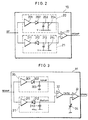
- An example of the amplitude indicating signal generating section 10 will be explained in more detail later with reference to Fig. 2.
- a disc type identifying section 11 identifies the type of an optical disc 1 on the basis of the amplitude indicating signal RFAMP, and outputs an identification result signal DTYPE.
- An example of the structure of the disc type identifying section 11 will be explained in more detail later with reference to Fig. 3.
- the amplitude indicating signal generating section 10 and the disc type identifying section 11 serve as identifying means.
- a controller 12 is constituted by a microcomputer, receives the identification result signal DTYPE from the disc type identifying section 11, controls the servo controlling section 7, readout signal controlling section 8 (or the optical pickup 4), etc. according to needs, and performs control relating to switching of the circuit characteristics (or switching of an optical system inside the optical pickup 4) and the entire operations of the device so as to achieve better signal reproduction and servo control characteristics.
- An upper envelope detector 20 and a lower envelope detector 21 constituting envelope detecting means are formed by buffer amplifiers 201, 211, diodes 202, 212, capacitors 203, 213, and resistors 204, 214, respectively.
- the upper envelope detector 20 and lower envelope detector 21 detect the positive peak by the diode 202 and capacitor 203, and detect the negative peak by the diode 212 and capacitor 213, respectively.
- a subtracter 22 calculates the amplitude of the readout signal RF (more precisely, the amplitude of the envelopes) by subtracting an output of the lower envelope detector 21 from an output of the upper envelope detector 20, and outputs the result as the amplitude indicating signal RFAMP.
- the gain of the subtracter 22 can be 1 or other arbitrary value.
- one of the connecting terminals of each of the capacitor 203 and resistor 204, which is not connected to the diode 202, is connected to a negative electric potential V-.
- one of the terminals of each of the capacitor 213 and resistor 214, which is not connected to the diode 212, is connected to a positive electric potential V+.
- the readout signal RF is not to be a negative voltage (for instance, an optical disc device using a single positive power supply)
- the range of voltage of the signal is from 0 volt to the positive power supply voltage. Therefore, it is preferred that the voltage which biases the capacitor of the envelope detector is set at 0 volt (the ground electric potential) in the upper envelope detector, and is set at the power supply voltage in the lower envelcpe detector.
- a peak detector 30 and a bottom detector 31 are formed by buffer amplifiers 301, 311, diodes 302, 312, and capacitors 303, 313, respectively.
- Each of the peak detector 30 and bottom detector 31 detects the maximum voltage (upper envelope) Vpeak and the minimum voltage (lower envelope) Vbottom by the diodes 302, 312 and capacitors 303, 313 after buffer-amplifying the input amplitude indicating signal RFAMP by the buffer amplifiers 301 or 311, respectively.
- a subtracter 32 calculates the difference Vamp between the maximum Vpeak and minimum Vbottom of the amplitude indicating signal RFAMP by subtracting the output of the lower envelope detector 31 from the output of the upper envelope detector 30.
- a comparator 33 as difference comparing means compares the voltage of a comparative voltage source 34 with the difference Vamp between the maximum value and minimum value of the amplitude indicating signal RFAMP obtained by the subtracter 32, and outputs the result of comparison as the identification result signal DTYPE.
- the voltage of the comparative voltage source 34 can be varied by the controller 12, etc.
- the readout signal RF and in turn the amplitude indicating signal RFAMP representing the amplitude of the readout signal RF vary. Therefore, in order to accurately identify the type of an optical disc, it is preferred that the voltage of the comparative voltage source 34 is variable as mentioned above. Needless to say, if there is no need to vary the voltage of the comparative voltage source 34 because of a small variation, the voltage of the comparative voltage source 34 can be set at a fixed value.
- the bias voltage to be applied to the capacitors 303, 313 can be 0 volt (ground electric potential) for the capacitor 303 in the peak detector 30, and be a positive supply voltage (+Vcc) for the capacitor 313 in the bottom detector 31.
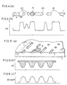
- Fig. 4(a) shows a state in which the light beam 6 is moved on a single information track 3 along its longitudinal (tangential) direction.
- Fig. 4(b) is a depiction showing changes in the readout signal RF with respect to time during movement of the light beam 6.
- the quantity of light reflected from the optical disc 1 decreases because the light beam 6 is diffracted by the pit 31, and thus the level of the readout signal RF is lowered.
- the light beam 6 is positioned between two pits 31 (for example in the B area in Fig.
- the quantity of light reflected from the optical disc 1 increases because it is hard to diffract the light beam 6, and therefore the level of the readout signal RF becomes higher.
- the interval between two pits 31 is longer than a value which is almost the same as the diameter of the light beam 6, the quantity of reflected light is near a value obtained when the light beam 6 is reflected by an almost flat surface.
- the amplitude of the readout signal RF corresponding to the quantity of reflected light is the difference between the high level and the low level. As illustrated in Fig. 4(b), when the light beam 6 is positioned on the center of the information track 3, the amplitude is increased.
- Figs. 5(a) to 5(c) and Figs. 6(a) to 6(c) are enlarged explanatory views depicting another states in which the light beam 6 is applied to the optical disc 1.
- Figs. 5(b) and 6(b) show changes in the readout signal RF (which are observed when the light beam 6 crosses the information track 3) according to the position of the light beam 6 relative to the information track 3 in a radial direction of the optical disc 1.
- Figs. 5(c) and 6(c) show changes in the amplitude indicating signal RFAMP according to the position of the light beam 6 relative to the information track 3 in a radial direction of the optical disc 1.
- Figs. 5(b) and 6(b) show changes in the readout signal RF (which are observed when the light beam 6 crosses the information track 3) according to the position of the light beam 6 relative to the information track 3 in a radial direction of the optical disc 1.
- Figs. 5(c) and 6(c) show
- FIGS. 5(a) and 6(a) are depictions showing the relative positional relation between the light beam 6 and the optical disc 1.
- Figs. 5(a) to 5(c) show their relation when the density of the information tracks 3 in a radial direction of the optical disc 1 is low.
- Figs. 6(a) to 6(c) show their relation when the density is high.
- the amplitude of the readout signal RF becomes smaller with a decrease in the ratio of an area of the information track 3 irradiated with the light beam 6 to the total area irradiated with the light beam 6, but becomes higher with an increase in the ratio. Accordingly, in the event when the light beam 6 is moved relatively to the information track 3 in a radial direction of the optical disc 1, the amplitude of the readout signal RF increases at the time the light beam 6 is positioned just above the information track 3, while the amplitude of the readout signal RF decreases at the time the light beam 6 is positioned between two adjacent information tracks 3. Thus, an increase and decrease in the amplitude repeatedly occurs.
- the light beam 6 is diffracted to some extent by the pits on the information tracks 3 on the right and left side of the light beam 6.
- the quantity of the light beam 6 is equivalent to the quantity of the light beam 6 applied to an almost flat portion of the optical disc 1, and the quantity of reflected light is large.
- the maximum value is substantially uniform regardless of whether the light beam 6 is positioned on the information track 3 or between the information tracks 3.
- the maximum level of the readout signal RF is determined in the above-mentioned manner.
- the DC component is temporarily cut off by AC coupling the readout signal RF so as to produce an AC signal around a new DC voltage. More specifically, by passing the readout signal RF through a high-pass filter 40 formed by a capacitor 401 and resister 402 shown in Fig. 7, the output becomes a signal RF' which varies around a reference voltage Vref regardless of the DC component of the original signal RF.
- the signal RF' output from the high-pass filter 40 may have a waveform that exhibits pulsation or shifts in the level of the original RF as shown in Fig. 8(b).
- the amplitude indicating signal generating section 10 of this embodiment which detects upper and lower envelopes and generates an amplitude indicating signal on the basis of the difference between the detected values, it is possible to generate a signal indicating the amplitude of the readout signal RF (or RF') accurately without being affected by such pulsation and shifts.
- the readout signal RF to be input to the amplitude indicating signal generating section 10 can be a signal retaining a DC component, or a signal after AC coupling, thereby ensuring high flexibility in designing the circuit.
- a readout signal RF retaining a DC component is shown in Fig. 8(a).
- the controller 12 gives instructions so that the spindle motor 9 is started to rotate at a specified rotation speed, the optical pickup 4 emits the light beam 6, and the servo control section 7 starts focus-servo-control to control the focal point of the converged light beam 6 to be on the information-recorded side 2 of the optical disc 1.
- the amplitude of the readout signal RF is increased and decreased, and the amplitude indicating signal RFAMP as the output of the amplitude indicating signal generating section 10 shown in Fig. 2 varies according to the increase and decrease in the amplitude of the readout signal RF.
- the disc type identifying section 11 observes the amplitude indicating signal RFAMP.
- the track pitch is large, i.e., when the density of the information tracks 3 in a radial direction of the optical disc 1 is low
- the variation in the amplitude indicating signal RFAMP is large, and the difference between the maximum value and the minimum value of the amplitude indicating signal RFAMP is big. Therefore, the difference between the maximum value and the minimum value of the amplitude indicating signal RFAMP is calculated (Vamp shown in Fig. 3).
- the difference exceeds a predetermined level (the voltage of the comparative voltage source 34 shown in Fig. 3), it is judged that the optical disc has a large track pitch, i.e., a low density of information tracks in the radial direction.
- a predetermined level the voltage of the comparative voltage source 34 shown in Fig. 3
- the optical disc has a small track pitch, i.e., a high density of information tracks in the radial direction.
- an identification result signal DTYPE is sent to the controller 12.
- the time taken for identification is around a time required for the light beam 6 to cross about several information tracks 3, and more specifically a very short time ranging from several ms to several ten ms.
- the voltage of the comparative voltage source 34 shown in Fig. 3 is determined according to the types of the discs to be identified. By setting the voltage at plural levels, it is possible to identify at least three types of discs. Moreover, the voltage of the comparative voltage source 34 is made variable according to changes in conditions such as the quantity of light of the light beam 6 as mentioned above.
- the controller 12 If the specified value of the rotation speed given in starting the spindle motor 9 is inappropriate, the controller 12 gives a new instruction to control the rotation speed according to the identification result signal DTYPE. Moreover, in order to achieve improved signal reproduction and servo control characteristics if necessary, the controller 12 instructs the servo control section 7, readout signal processing section 8, optical pickup 4, etc. to switch the circuit characteristics and the optical system inside the optical pickup 4. Alternatively, when switching the characteristics of the servo control section 7, the controller 12 interrupts the focus servo control temporarily, and performs a control to resume the focus serve after switching the characteristics of the serve control section 7, if necessary. Thereafter, the controller 12 controls the servo control section 7 to start tracking servo control for reproduction of information.
- the identification of the types of optical discs, and all or almost all of operations for switching the characteristics of the respective sections of the device according to the identification can be performed simultaneously within a time (usually ranging from around several hundred millisecond to around several second) which is taken for the optical disc 1 to reach a steady rotation speed, i.e., a rotation speed required to normally reproduce recorded information, after sending the start rotation instruction to the spindle motor 9.
- a steady rotation speed i.e., a rotation speed required to normally reproduce recorded information
- the identification of the type of the optical disc 1 can be started if the focus servo control is started. Namely, it is possible to start the identification of the type of the optical disc 1 even if the spindle motor 9 and the optical disc 1 do not reach a predetermined rotation speed and tracking servo control is not performed.
- the second embodiment of the present invention differs from the first embodiment in the structure and operation of the disc type identifying section 11.
- first and second embodiments will be explained, and explanations for the same structures and operations will be omitted.
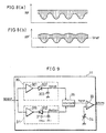
- Fig. 9 shows the structure of the disc type identifying section 11 of the second embodiment.
- Each of the peak detector 30 and bottom detector 31 are the same as the first embodiment shown in Fig. 3 in terms of their inner structure and ability to detect the maximum value Vpeak and the minimum value Vbottom of the input amplitude indicating signal RFAMP.
- a divider 35 outputs the result of dividing Vpeak by Vbottom, i.e., the ratio Vquot between Vpeak and Vbottom.
- the comparator 33 (ratio comparing means) compares the voltage of the comparative voltage source 34 and the ratio Vquot between the maximum value and the minimum value of the amplitude indicating signal RFAMP, given by the divider 35, and outputs the identification result signal DTYPE which indicates whether the ratio Vquot is greater or smaller than the voltage.
- the disc type identifying section 11 of the second embodiment calculates the ratio between the maximum value Vpeak and the minimum value Vbottom of the amplitude indicating signal RFAMP by dividing Vpeak by Vbottom.
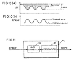
- Equation (1), (2) and the signals RF, RFAMP are shown in Figs. 10(a) and 10(b).
- the gains of the buffer amplifiers 301, 311 in the peak detector 30 and bottom detector 31 of the disc type identifying section 11 shown in Fig. 9 are set at 1.
- Equation (3) does not include any term relating to the sensitivity and characteristics of the optical pickup 4, the quantity of the light beam 6, or the reflectivity and modulation factor of the optical disc 1. Equation (3) includes only a term d. As explained in the first embodiment with reference to Figs. 4 (a), (b) to 6(a), (b), (c), since this term relates to the track pitch of the optical disc 1, i.e., the density of the information tracks 3 in a radial direction of the optical disc 1, it can be said that it is possible to extract only the information relating to the track pitch by division. Consequently, in the second embodiment, it is possible to more accurately distinguish optical discs of different track pitches.
- the voltage of the comparative voltage source 34 is preferably made variable so as to meet the variations in the characteristic terms.
- the disc type identifying section 11 of the second embodiment only extracts the term relating to the track pitch of the information tracks 3 on the optical disc 1 in theory, and is not affected by the variations in the other various terms.
- the voltage of the comparative voltage source 34 can be set at a fixed value.
- this voltage is determined according to the type of an optical disc to be identified. If the voltage is set at a plurality of values, it is possible to identify more than two types of the optical discs.
- the third embodiment of the present invention differs from the second embodiment in the structure of the disc type identifying section 11.
- the differences will be explained, and explanations for the same structures as in the first and second embodiments will be omitted.
- the disc type identifying section 11 of the second embodiment distinguishes optical discs 1 whose track pitch of the information tracks 3 differs from each other by processing the amplitude indicating signal RFAMP mainly in analog circuits such as the peak detector, the bottom detector, and the divider.
- the disc type identifying section 11 of the third embodiment performs a similar operation by converting the amplitude indicating signal RFAMP into digital data by an A/D converter, and by digitally processing the digital data in a microcomputer. This processing can be executed with a program recorded on a recording medium such as an optical disc.
- Fig. 11 shcws the structure of the disc type identifying section 11 of the third embodiment.
- An A/D converter 36 converts the input amplitude indicating signal RFAMP into digital data.
- a microcomputer 37 reads the digital data of the RFAMP output from the A/D converter 36, performs processing based on software, to be described later, for identifying the type of the optical disc, and outputs the identification result signal DTYPE.
- the microcomputer 37 performs processing based on software as follows:
- the digital data is read out from the A/D converter 36 in a period between several ms and several ten ms. In this period, the light beam 6 usually passes across at least several information tracks 3 on the optical disc 1. Therefore, if the maximum value and the minimum value of the digital data in this period are extracted, it is possible to obtain the result equivalent to the result obtained by detecting the maximum value and the minimum value of the RFAMP by the peak detector 30 and the bottom detector 31 in the second embodiment.
- step (2) division like that performed by the divider 35 is carried out.
- step (3) the result of step (2) and the voltage of the comparative voltage source 34 are compared in the same manner as in the comparator 33. Therefore, when the operations of the disc type identifying section 11 of the second and third embodiments are seen from the outside, there is no difference between them.
- the third embodiment can possess the merits of the disc type identifying section 11 of the second embodiment.
- the structure of the third embodiment since the disc type identifying section 11 can carry out all of the processing steps based on software after converting the amplitude indicating signal RFAMP into digital data by the A/D converter 36, no analog circuit is required. Consequently, the structure of the third embodiment has new merits in terms of the stability of operation and the integration of circuits.
- the microcomputer 37 of the disc type identifying section 11, and the A/D converter 36 can be integrated with the microcomputer for the controller 12. In this case, it is possible to produce further merits in the cost, the on-board circuit size, etc.
- the fourth embodiment of the present: invention illustrates a modified example of the structure of the amplitude indicating signal generating section 10 shown in Fig. 2 of the first embodiment.
- this embodiment illustrates a modified example of the structure of the amplitude indicating signal generating section 10 shown in Fig. 2 of the first embodiment.
- the amplitude indicating signal generating section 10 shown in Fig. 2 detects both of the upper envelope and the lower envelope of a readout signal RF, and generates an amplitude indicating signal RFAMP based on the difference therebetween. However, it is possible to generate a signal indicating the amplitude of the readout signal RF by calculating the mean value of the readout signal RF.
- the fourth embodiment employs this approach as described in detail below.
- the readout signal RF (which retains the original DC component without AC coupling) when the light beam 6 was moved across the information track 3 in a radial direction of the optical disc 1.
- the upper envelope does not show a much change irrespective of whether the light beam 6 is positioned on the information track 3 or between the information tracks 3 because of the following reason.
- the lower envelope varies according to an increase and decrease in the quantity of the reflected light.
- Fig. 12(a) is a depiction indicating the relative positional relation between the light beam 6 and the information track 3.
- Fig. 12(b) is a view indicating the mean value of the readout signal RF.
- Fig. 12(c) is a view explaining the amplitude indicating signal RFAMP when the readout signal RF is represented by the difference between the maximum and the minimum values and by the average thereof.
- the average value represents the intermediate value between the upper envelope and the lower envelope, i.e., a level given by dividing the sum of the upper envelope and the lower envelope by 2.
- the levels of the upper and lower envelopes of the readout signal RF are denoted by RFp and RFb, respectively.
- a subscript "1" is added when the light beam 6 is positioned on the information track 3, while a subscript "2" is added when the light beam 6 is positioned between the information tracks 3.
- the results of calculating an amplitude indicating signal based on the difference between the upper and lower envelopes or the mean value of the readout signal RF are distinguished from each other by adding a subscript "1" or "2" to RFAMP(dif) and RFAMP(avg) according to the position of the light beam 6, the respective amplitude indicating signals can be given by equations (8) to (11) below.
- the amplitude indicating signal RFAMP(avg) obtained by the mean value of the readout signal RF shows a half of the amplitude, and its polarity is inverted (see Fig. 12(c)).
- the level of the amplitude indicating signal when the light beam 6 is positioned between the information tracks 3 is in inverse relation to the level of the amplitude indicating signal when the light beam 6 is positioned on the information track 3, and the amplitude in the former case is half of the amplitude in the latter case. If these factors are taken into consideration, it is possible to distinguish the types of optical discs having different track pitches based on the amplitude indicating signal obtained from the mean value of the readout signal RF.
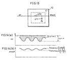
- Fig. 13 shows the structure of the amplitude indicating signal generating section 10 of the fourth embodiment.
- a low-pass filter 41 (mean value detecting means) is formed by a resister 410 and a capacitor 411.
- the cutoff frequency of the low-pass filter 41 which is determined by the time constants of the resister 410 and capacitor 411 are arranged to be higher than the repetitive frequency of the information tracks 3 expected when the light beam 6 is moved across the information tracks 3, but lower than the signal frequency of the readout signal RF.
- the signal frequency of the RF is usually between several hundred kHz and several MHz.
- the rotation speed becomes much lower than the steady value. Since it is usually sufficient for estimating the rotation speed to be lowered to about one tenth of the steady value, the signal frequency of the readout signal RF in starting the rotation of the spindle motor 9 can be estimated between several ten kHz and several hundred kHz. On the contrary, since the estimated repetitive frequency of the information tracks 3 when the light beam 6 is moved across the information tracks 3 is usually between about several hundred Hz and about several kHz, it is appropriate to set the cutoff frequency of the low-pass filter 41 between about several hundred kHz and about several ten kHz.
- the amplitude indicating signal generating section 10 of the fourth embodiment can be formed by a simple low-pass filter 41, it is possible to construct the amplitude indicating signal generating section 10 at low cost.
- the difference between the peak value and the bottom value of the amplitude indicating signal can be obtained like in the disc type identifying section 11 of the first embodiment, or the result of division (ratio) between the peak value and the bottom value can be obtained like in the second embodiment or the third embodiment.
- Figs. 14(a) and 14(b) indicate changes in the readout signal RF and changes in the amplitude indicating signal RFAMP obtained from the mean value of the readout RF, respectively when the light beam 6 was moved across the information tracks 3 in a radial direction of the optical disc 1.
- the definitions of the letters used in equations (1) and (2) of the second embodiment are used for indication of the level and amplitude of the signal.
- equation (16) includes all of the terms relating to the sensitivity and characteristic of the optical pickup 4, the quantity of the light beam 6, and reflectivity and modulation factor of the optical disc 1, etc., the Vamp given by equation (16) is more easily affected by changes in these terms than the Vquot given by equation (17) which only includes the terms m and d relating to the modulation factor of the optical disc 1.
- equation (17) which only includes the terms m and d relating to the modulation factor of the optical disc 1.
- the fifth embodiment further modifies the structure of the amplitude indicating signal generating section 10.
- Fig. 15 is a block diagram of an optical disc device of the fifth embodiment. As for the components explained in the first to the fourth embodiments, the same numerals as those used in the previous embodiments are given, and explanations thereof are omitted here.
- the fifth embodiment is explained by supposing that the disc type identifying section 11 shown in Fig. 15 has the structure explained in Fig. 11 of the third embodiment.
- this disc type identifying section 11 can have any of the structures described in the first to third embodiments.
- a control signal VAGC is newly applied to the amplitude signal indicating section 10 from the readout signal processing section 8
- a response switching control signal TCNG is newly applied to the readout signal processing section 8 from the controller 12.
- the readout signal processing section 8 performs automatic gain control (AGC) for adjusting the amplitude of the readout signal RF to a predetermined value, and reproduction of the recorded information by demodulating the readout signal RF.
- AGC automatic gain control
- the automatic gain control amplifies the input readout signal RF by introducing small gain when the amplitude of the RF is large or amplifies the input readout signal RF by introducing large gain when the amplitude thereof is small, and outputs the resultant signal to the subsequent processing circuit.
- the automatic gain control detects the amplitude of the RF, and uses a signal corresponding to the amplitude for the internal gain control. Therefore, if this signal is observed when the light beam is moving across the information tracks, the signal should vary according to changes in the amplitude of the RF during the movement of the light beam across the information tracks. Therefore, the types of optical discs having different track pitches should be distinguished from each other based on the degree of the changes in the amplitude.
- the signal applied to the amplitude indicating signal generating section 10 is not the readout signal RF, but is the signal for controlling the gain in the readout signal processing section 8, i.e., the AGC control signal VAGC.
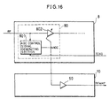
- Fig. 16 shows the structures of the readout processing section 8 and the amplitude indicating signal generating section 10. However, in Fig. 16, only the portions of the readout signal processing section 8, which are necessary to explain the relation with the amplitude indicating signal generating section 10, are illustrated.
- an AGC section 80 for performing AGC control on the input readout signal RF is formed by an AGC control signal generating section 801, and a variable gain amplifier 802 for varying the degree of the amplification of the input signal RF according to the value of the AGC control signal.
- the AGC control signal generating section 801 generates an AGC control signal VAGC of high level when the amplitude of the input readout signal RF is large, or generates an AGC control signal VAGC of low level when the amplitude of the input readout signal RF is small.
- the variable gain amplifier 802 introduces low amplification gain when the level of the VAGC is high, or high amplification gain when the level of the VAGC is low.
- the AGC control signal generating section 801 is supplied with the response switching control signal TCNG from the controller 12 as to be described later.
- the amplitude indicating signal generating section 10 only includes an amplifier 50, and amplifies the AGC control signal VAGC from the readout signal processing section 8 by using the amplifier 50 and outputs the resultant signal as the amplitude indicating signal RFAMP.
- the amplifier 50 introduces any gain. As an extreme example, if the gain is set at 1, it is possible to remove the amplifier 50 and use the VAGC as the RFAMP.
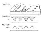
- Fig. 17(c) illustrates changes in the AGC control signal VAGC which is output from the readout signal processing section of the fifth embodiment when the light beam 6 is moved across the information tracks 3.
- Fig. 17(a) shows the relative positional relationship between the light beam 6 and information track 3.
- Fig. 17(b) shows changes in the AGC control signal VAGC.
- the VAGC increases or decreases according to the changes in the amplitude of the RF. Therefore, if the VAGC is amplified according to a need and is used as the amplitude indicating signal RFAMP, it is possible to distinguish optical discs having different track pitches by the application of the means and method explained in the first to the fourth embodiments.
- the AGC processing absorbs the changes in the amplitude of the readout signal RF due to the rotation of the optical disc, adjusts the amplitude of the readout signal RF to a constant amplitude, and then supplies the readout signal RF to the subsequent circuit. Therefore, the response speed of the AGC processing is usually set at a value about several times of the rotation frequency of the optical disc so that the AGC processing does not respond to scratches or the like on the optical disc. However, with such a slow response speed, the VAGC does not follow the changes in the amplitude of the RF which occur when the light beam 6 crosses the information tracks 3.
- the response switching control signal TCNG is applied from the controller 12 to the AGC control signal generating section 801 of this embodiment so as to switch the response speed to a quicker response speed during a period in which the light beam 6 crosses the information tracks 3 to identify the type of the optical disc.
- the level of the readout signal RF and the level of the AGC control signal VAGC have inverse relation depending on the type of the AGC section 80.
- the present invention does not suffer from any problems because it identifies the type of an optical disc based only on the difference between the peak value and bottom value of the amplitude indicating signal RFAMP or the ratio between the peak value and bottom value thereof.
- the AGC control signal is used as the amplitude indicating signal of the readout signal RF in the automatic gain control (AGC) function which is usually provided in the readout signal processing section 8 for processing the readout signal RF in the optical disc device. Consequently, the structure of the amplitude indicating signal generating section 10 is simplified, thereby producing further advantages in terms of the cost and mounting the circuits.
- AGC automatic gain control
- the amplitude indicating signal of the present invention needs to be a signal which varies according to a change in the amplitude of the readout signal, more specifically a signal which varies according to a change in the total quantity of reflected light received by the optical pickup.
- the amplitude indicating signal of the present invention is not necessarily limited to the signal explained in the above-mentioned embodiments (the signal produced by detecting the amplitude of the readout signal, i.e., AGC control signal).
- the axis of rotation of the optical disc 1 and the center of concentric or spiral information tracks 3 do not usually coincide with each other. Therefore, even if the position of the light beam 6 is fixed, the light beam 6 is displaced relatively to the information track 3 with a rotation of the optical disc 1, and crosses the information track 3. Accordingly, the amplitude of the readout signal RF and the amplitude indicating signal RFAMP vary. These phenomena are in fact observed in almost all cases, and the respective means described in the above-mentioned embodiments operate so as to achieve the object of the present invention in accordance with the fact.
- the lens 5 is driven in a radial direction of the optical disc 1 when identifying the type of the optical disc 1, even when the eccentricity of the optical disc 1 is extremely small or even when the lens 5 is vibrated due to disturbance, the light beam 6 is arranged to certainly cross the information track 3.
- Fig. 18 shows a block diagram of the optical disc device of this embodiment.
- the block diagram is basically the same as that of the first embodiment shown in Fig. 1.
- the disc type identifying section 11 may have any of the above-mentioned structures, it is supposed in the sixth embodiment that the disc type identifying section 11 has the structure explained in the third embodiment shown in Fig. 11.
- a lens drive signal LMOVE is input to the servo control section 7 from the controller 12.
- the following description will explain an optical disc device having the structure shown in Fig. 18. However, the explanations for the same structures as those of the first to the fifth embodiments will be omitted here.
- the controller 12 when identifying the type of the optical disc 1, the controller 12 outputs the signal LMOVE, and the servo control section 7 drives the lens 5 in a radial direction of the optical disc 1 according to the LMOVE (identification drive means). Therefore, even when the eccentricity of the optical disc 1 is very small or even when the lens 5 vibrates due to disturbance, the light beam 6 6 is quickly and certainly moved across the information tracks 3. Consequently, the amplitude of the readout signal RF and the amplitude indicating signal RFAMP certainly vary quickly. It is thus possible to identify the type of the optical disc 1 in a short time, and prevent an unnecessary increase in the starting time of the optical disc device.
- the controller 12 may increase the level of the signal LMOVE gradually while observing the tracking error signal TES or the amplitude indicating signal RFAMP, and then the servo control section 7 may increase the amount by which the lens 5 is driven according to the increase in the level of the LMOVE so that outputting the signal LMOVE, i.e., driving the lens 5, is stopped at the time the light beam 6 crosses a minimum number of the information tracks 3 required for identifying the type of the optical disc 1.
- the movement of the lens 5 is limited to such an amount that the light beam 6 is moved across the minimum number of the information tracks 3 to identify the type of the optical disc 1. Therefore, the displacement of the lens 5 from the original center position is limited to a small value, and the tracking servo control (pulling the servo) is smoothly started after the identifying process, thereby producing a further advantage.
- Fig. 19(b) shows changes in the readout signal RF, which are caused by the movement of the light beam 6 across the information tracks 3 when the lens 5 is moved in a radial direction of the optical disc 1.
- Fig. 19(a) shows the relation between the relative positions of the light beam 6 and information track 3.
- Fig. 19(b) shows changes in the readout signal RF corresponding to Fig. 19(a).
- Fig. 19(a) suppose that the lens 5 is moved in a radial direction (either of directions a and b) of the optical disc 1, for example, in the direction a shown in Fig. 19(a).
- the eccentricity of the optical disc 1 is very small, even when the lens 5 is driven in either of the directions a and b, the relative speed of the light beam 6 to the information track 3 is increased.
- the light beam 6 certainly crosses the information tracks 3, it is possible to quickly identify the type of the optical disc 1 using the technique of the present invention described in the above-mentioned embodiments.
- the eccentricity of the optical disc 1 is large, when the optical disc 1 rotates, the information tracks 3 move in both of the directions a and b with respect to the light beam 6.
- the lens 5 is driven in the direction a, the information track 3 is moved in the same direction, and the relative speed of the light beam 6 and the information track 3 is rather lowered.
- Fig. 20(a) shows the relative positional relation between the light beam 6 and the information track 3
- Fig. 20(b) shows changes in the readout signal RF.
- Fig. 21(a) shows the relative positional relationship between the light beam 6 and the information track 3.
- Fig. 21(b) shows changes in the readout signal RF.
- the lens supporting mechanism of the optical pickup 4 supports the lens 5 at the neutral zero point in a tracking direction (a radial direction of the optical disc 1) by springs 501.
- the lens 5 when the lens 5 is once driven in the direction a by the signal LMOVE and is then stopped, the lens 5 returns to the original neutral zero point by the returning force of the springs 501 (returning means).
- the moving direction of the light beam 6 with respect to the information track 3 is switched in the process of driving the lens 5 in the direction a and in the process of moving the lens 5 back to the zero point.
Claims (14)
- Dispositif à disque optique destiné à la reproduction d'informations enregistrées sur une piste contenant des informations (3) d'un disque optique (1) sous la forme d'un signal de lecture (RF) en utilisant un capteur de lecture (4) pour appliquer un faisceau lumineux (6) à une face contenant des informations enregistrées (2) du disque optique (1) et recevoir la lumière réfléchie par la face contenant des informations enregistrées (2), dans lequel
ledit dispositif à disque optique comprend :caractérisé en ce queun moyen de génération de signal d'indication d'amplitude (10) destiné à générer un signal d'indication d'amplitude (RFAMP) pour discriminer le type de disques optiques (1) présentant des densités différentes de pistes contenant des informations selon des directions radiales des disques en fonction d'un niveau d'amplitude du signal de lecture (RF),
le moyen de génération de signal d'indication d'amplitude (10) utilise, pour la génération dudit signal d'indication d'amplitude, ledit signal de lecture (RF) représentant la quantité d'un faisceau lumineux réfléchi par la piste contenant des informations (3) et sa variation d'amplitude lorsque ledit faisceau lumineux (6) se déplace par rapport à la piste contenant des informations (3) selon une direction radiale du disque optique,
dans lequel ledit signal d'indication d'amplitude (RFAMP) varie en fonction de ladite variation d'amplitude dudit signal de lecture (RF), et
ledit dispositif à disque optique comprend en outre un moyen d'identification (11) destiné à identifier un type de disque optique (1) en fonction desdites densités différentes de pistes contenant des informations (3) selon des directions radiales des disques optiques (1) par comparaison d'une différence entre une valeur maximale et une valeur minimale du signal d'indication d'amplitude (RFAMP) avec une valeur prédéterminée. - Dispositif à disque optique destiné à la reproduction d'informations enregistrées sur une piste contenant des informations (3) d'un disque optique (1) sous la forme d'un signal de lecture (RF) en utilisant un capteur de lecture (4) pour appliquer un faisceau lumineux (6) à une face contenant des informations enregistrées (2) du disque optique (1) et recevoir la lumière réfléchie par la face contenant des informations enregistrées (2), dans lequel
ledit dispositif à disque optique comprend :caractérisé en ce queun moyen de génération de signal d'indication d'amplitude (10) destiné à générer un signal d'indication d'amplitude (RFAMP) pour discriminer le type de disques optiques (1) présentant des densités différentes de pistes contenant des informations selon des directions radiales des disques en fonction d'un niveau d'amplitude du signal de lecture (RF),
le moyen de génération de signal d'indication d'amplitude (10) utilise, pour la génération dudit signal d'indication d'amplitude, ledit signal de lecture (RF) représentant la quantité d'un faisceau lumineux réfléchi par la piste contenant des informations (3) et sa variation d'amplitude lorsque ledit faisceau lumineux (6) se déplace par rapport à la piste contenant des informations (3) selon une direction radiale du disque optique,
dans lequel ledit signal d'indication d'amplitude (RFAMP) varie en fonction de ladite variation d'amplitude dudit signal de lecture (RF), et
ledit dispositif à disque optique comprend en outre un moyen d'identification (11) destiné à identifier un type de disque optique (1) en fonction desdites densités différentes de pistes contenant des informations (3) selon des directions radiales des disques optiques (1) par comparaison d'un rapport entre une valeur maximale et une valeur minimale du signal d'indication d'amplitude (RFAMP) avec une valeur prédéterminée. - Dispositif à disque optique selon la revendication 2,
dans lequel ledit moyen d'identification (11) comprend un moyen diviseur (35) destiné à calculer le rapport en divisant la valeur maximale du signal d'indication d'amplitude (RFAMP) par la valeur minimale. - Dispositif à disque optique selon la revendication 2,
dans lequel ledit moyen d'identification (11) comprend :un convertisseur analogique/numérique (36) destiné à convertir le signal d'indication d'amplitude (RFAMP) en données numériques ; etun micro-ordinateur (37) destiné à extraire une valeur maximale et une valeur minimale de la sortie de données numériques dudit convertisseur analogique/numérique (36), à calculer le rapport en divisant la valeur maximale par la valeur minimale et à comparer le rapport avec une valeur prédéterminée. - Dispositif à disque optique selon l'une quelconque des revendications 1 à 4,
dans lequel ledit moyen de génération de signal d'indication d'amplitude (10) comprend un moyen de détection d'enveloppe (20, 21) destiné à détecter des enveloppes dudit signal de lecture (RF) et génère le signal d'indication d'amplitude (RFAMP) en fonction des enveloppes. - Dispositif à disque optique selon l'une quelconque des revendications 1 à 4,
dans lequel ledit moyen de génération de signal d'indication d'amplitude (10) comprend un moyen de détection de valeur moyenne (41) destiné à détecter une valeur moyenne du signal de lecture (RF) et génère le signal d'indication d'amplitude (RFAMP) en fonction de la valeur moyenne. - Dispositif à disque optique selon l'une quelconque des revendications 1 à 6,
dans lequel ledit moyen d'identification (11) identifie le type de disque optique (1) dans un état dans lequel le faisceau lumineux (6) est stoppé dans une position sans être commandé dans une direction radiale du disque optique. - Dispositif à disque optique selon l'une quelconque des revendications 1 à 6,
dans lequel ledit moyen d'identification (11) comprend un moyen d'identification de commande (7) destiné à commander le faisceau lumineux (6) de telle sorte que la piste contenant des informations (3) et le faisceau lumineux (6) se déplacent relativement dans une direction radiale du disque optique. - Dispositif à disque optique selon la revendication 8,
dans lequel ledit moyen d'identification de commande (7) fait augmenter graduellement un degré de commande du faisceau lumineux (6). - Dispositif à disque optique selon la revendication 8,
dans lequel ledit moyen d'identification de commande (7) commande le faisceau lumineux (6) selon deux directions le long d'une direction radiale du disque optique (1). - Dispositif à disque optique selon la revendication 10,
dans lequel ledit moyen d'identification de commande (7) commande le faisceau lumineux (6) selon deux directions le long d'une direction radiale du disque optique (1) pour une durée uniforme à une amplitude uniforme. - Dispositif à disque optique selon la revendication 10,
dans lequel ledit moyen d'identification de commande (7) commande le faisceau lumineux (6) selon une direction au choix le long d'une direction radiale du disque optique (1), et
ledit capteur de lecture (4) comprend un moyen de renvoi (501) destiné à renvoyer le faisceau lumineux dans une position neutre après la commande. - Dispositif à disque optique selon la revendication 1 ou 2, comprenant en outre un moyen de génération de signal de commande automatique de gain (801) destiné à générer un signal de commande automatique de gain (VAGC) destiné à commander le gain d'un amplificateur à gain variable (802) pour ajuster l'amplitude du signal de lecture (RF) à une amplitude uniforme en absorbant une modification d'amplitude du signal de lecture (RF) due à la rotation du disque optique (1),
dans lequel ledit moyen de génération de signal d'indication d'amplitude (10) comprend un amplificateur (50) destiné à amplifier le signal de commande automatique de gain (VAGC). - Dispositif à disque optique selon la revendication 13, comprenant en outre un moyen de commande de réponse (12) destiné à commander une vitesse de réponse dudit moyen de génération de signal de commande automatique de gain (801) à une valeur supérieure à une vitesse normale lors de l'identification du type du disque optique.
Applications Claiming Priority (2)
| Application Number | Priority Date | Filing Date | Title |
|---|---|---|---|
| JP9343529A JPH11176070A (ja) | 1997-12-15 | 1997-12-15 | 光ディスク装置 |
| JP34352997 | 1997-12-15 |
Publications (3)
| Publication Number | Publication Date |
|---|---|
| EP0926662A2 EP0926662A2 (fr) | 1999-06-30 |
| EP0926662A3 EP0926662A3 (fr) | 1999-08-11 |
| EP0926662B1 true EP0926662B1 (fr) | 2002-04-10 |
Family
ID=18362230
Family Applications (1)
| Application Number | Title | Priority Date | Filing Date |
|---|---|---|---|
| EP98123460A Expired - Lifetime EP0926662B1 (fr) | 1997-12-15 | 1998-12-11 | Dispositif à disque optique |
Country Status (8)
| Country | Link |
|---|---|
| US (1) | US6298024B1 (fr) |
| EP (1) | EP0926662B1 (fr) |
| JP (1) | JPH11176070A (fr) |
| KR (1) | KR100284536B1 (fr) |
| CN (1) | CN1174383C (fr) |
| CA (1) | CA2255390C (fr) |
| DE (1) | DE69804752T2 (fr) |
| TW (1) | TW407268B (fr) |
Families Citing this family (20)
| Publication number | Priority date | Publication date | Assignee | Title |
|---|---|---|---|---|
| US6449519B1 (en) * | 1997-10-22 | 2002-09-10 | Victor Company Of Japan, Limited | Audio information processing method, audio information processing apparatus, and method of recording audio information on recording medium |
| JP3503513B2 (ja) * | 1999-02-22 | 2004-03-08 | ヤマハ株式会社 | 光ディスク記録方法及び装置 |
| KR100571983B1 (ko) * | 1999-03-30 | 2006-04-17 | 삼성전자주식회사 | 광디스크 판별장치 및 그 방법 |
| JP2000298858A (ja) * | 1999-04-15 | 2000-10-24 | Funai Electric Co Ltd | 光ディスク装置の制御方法 |
| KR100636116B1 (ko) | 1999-12-02 | 2006-10-18 | 삼성전자주식회사 | 디스크 종류 판단방법 및 장치 |
| JP2001184773A (ja) * | 1999-12-28 | 2001-07-06 | Pioneer Electronic Corp | ディスクプレーヤ |
| JP2002304748A (ja) * | 2001-04-05 | 2002-10-18 | Pioneer Electronic Corp | 光ディスク再生装置及び光ディスク判別方法 |
| KR100425461B1 (ko) * | 2001-08-29 | 2004-03-30 | 삼성전자주식회사 | 디스크 판별 장치 및 방법 |
| EP1492099A1 (fr) | 2002-03-29 | 2004-12-29 | Sony Corporation | Dispositif d'identification de disque optique, procede d'identification de disque optique, enregistreur de disque optique, et dispositif de reproduction de disque optique |
| DE60319838T2 (de) * | 2002-08-30 | 2009-04-23 | Matsushita Electric Industrial Co., Ltd., Kadoma-shi | Optischer plattenspieler |
| KR100524949B1 (ko) * | 2003-02-27 | 2005-11-01 | 삼성전자주식회사 | 광디스크의 배속에 따라 증폭이득을 제어하는 광신호변환장치 및 그의 증폭이득 제어방법 |
| KR20050007811A (ko) * | 2003-07-11 | 2005-01-21 | 삼성전자주식회사 | 광 디스크 판별 방법 및 그 장치 |
| US20050254361A1 (en) * | 2004-04-13 | 2005-11-17 | Via Technologies, Inc. | Device and method for controlling recording speed of a recording and reproducing apparatus |
| EP2184737B1 (fr) * | 2004-11-02 | 2011-10-12 | Panasonic Corporation | Dispositif de traitement d'informations, dispositif d'accès, support d'enregistrement, méthode de traitement d'informations et programme de traitement d'informations |
| CN100380491C (zh) * | 2005-06-07 | 2008-04-09 | 威盛电子股份有限公司 | 光碟片判别方法 |
| CN100380490C (zh) * | 2005-06-08 | 2008-04-09 | 威盛电子股份有限公司 | 光碟片判别方法 |
| KR100790967B1 (ko) * | 2005-07-27 | 2008-01-02 | 삼성전자주식회사 | 자동이득 조절기의 제어전압을 디지털적으로 제어할 수있는 자동이득 조절기 및 제어방법 |
| CN101000785B (zh) * | 2006-01-13 | 2010-05-12 | 鸿富锦精密工业(深圳)有限公司 | 盘片种类识别方法与系统 |
| US7801003B2 (en) * | 2007-06-04 | 2010-09-21 | Victor Company Of Japan, Limited | Optical disc type determining method and optical disc device |
| TWI369676B (en) * | 2008-07-18 | 2012-08-01 | Sunplus Technology Co Ltd | Method and apparatus of discriminating different types of optical disks |
Family Cites Families (7)
| Publication number | Priority date | Publication date | Assignee | Title |
|---|---|---|---|---|
| JP2844783B2 (ja) | 1990-01-09 | 1999-01-06 | ソニー株式会社 | ディスク再生装置 |
| JPH0411325A (ja) | 1990-04-27 | 1992-01-16 | Sony Corp | 光ディスク記録装置 |
| JP2981030B2 (ja) | 1991-08-01 | 1999-11-22 | パイオニア株式会社 | 追記型光ディスクの再生方法及び光ディスク再生装置 |
| EP0520461A3 (en) | 1991-06-28 | 1993-03-31 | Kabushiki Kaisha Kenwood | Optical disk record/reproduction device |
| JP3570791B2 (ja) | 1995-03-28 | 2004-09-29 | パイオニア株式会社 | デジタルデータ記録異種媒体情報再生装置 |
| JPH09270167A (ja) | 1996-03-29 | 1997-10-14 | Sony Corp | 光ディスク種別判別装置及び光ディスクプレーヤ装置 |
| JPH10334574A (ja) | 1997-05-27 | 1998-12-18 | Victor Co Of Japan Ltd | 光ディスク判別装置 |
-
1997
- 1997-12-15 JP JP9343529A patent/JPH11176070A/ja active Pending
-
1998
- 1998-12-09 CA CA002255390A patent/CA2255390C/fr not_active Expired - Fee Related
- 1998-12-09 TW TW087120401A patent/TW407268B/zh active
- 1998-12-10 US US09/208,934 patent/US6298024B1/en not_active Expired - Fee Related
- 1998-12-11 EP EP98123460A patent/EP0926662B1/fr not_active Expired - Lifetime
- 1998-12-11 DE DE69804752T patent/DE69804752T2/de not_active Expired - Fee Related
- 1998-12-15 CN CNB981253687A patent/CN1174383C/zh not_active Expired - Fee Related
- 1998-12-15 KR KR1019980055149A patent/KR100284536B1/ko not_active IP Right Cessation
Also Published As
| Publication number | Publication date |
|---|---|
| CA2255390A1 (fr) | 1999-06-15 |
| TW407268B (en) | 2000-10-01 |
| KR19990063074A (ko) | 1999-07-26 |
| EP0926662A3 (fr) | 1999-08-11 |
| DE69804752T2 (de) | 2002-11-21 |
| KR100284536B1 (ko) | 2001-04-02 |
| US6298024B1 (en) | 2001-10-02 |
| DE69804752D1 (de) | 2002-05-16 |
| JPH11176070A (ja) | 1999-07-02 |
| CN1220444A (zh) | 1999-06-23 |
| EP0926662A2 (fr) | 1999-06-30 |
| CA2255390C (fr) | 2001-08-14 |
| CN1174383C (zh) | 2004-11-03 |
Similar Documents
| Publication | Publication Date | Title |
|---|---|---|
| EP0926662B1 (fr) | Dispositif à disque optique | |
| US6760289B1 (en) | Optical disc drive and method of discriminating various types of optical discs | |
| US6816443B1 (en) | Apparatus for discriminating optical disc and method therefor | |
| US5886963A (en) | Gain control device for servo control | |
| JPH09106617A (ja) | 情報記録媒体判別方法及び装置並びにフォーカスサーボ制御方法及び装置 | |
| US5859824A (en) | Digital disk player | |
| EP0388519A2 (fr) | Méthode pour régler le gain de boucle de boucles d'asservissement dans un lecteur de disque | |
| US5600615A (en) | Device and method for automatically controlling a servo loop gain | |
| JP2002260248A (ja) | ミラー検出信号生成回路 | |
| US6141307A (en) | Optical disk discriminating apparatus | |
| JP3714458B2 (ja) | 光学式ディスクプレーヤのサーボ制御装置 | |
| JP3872619B2 (ja) | バイアス電圧制御装置並びに情報再生装置及び情報記録装置 | |
| EP1091352B1 (fr) | Appareil de commande d'asservissement de focalisation, appareil de reproduction d'informations et appareil d'enregistrement d'informations | |
| JP3685690B2 (ja) | 再生専用光ディスク装置 | |
| KR100285633B1 (ko) | 광디스크 장치의 트랙 서보 제어방법 및 장치 | |
| JP2000222744A (ja) | 光ディスク装置およびフォーカスサーボ制御装置 | |
| KR100285764B1 (ko) | 광디스크 장치의 트랙 서보 제어방법 및 장치 | |
| KR100556495B1 (ko) | 광 디스크 기록 재생 방법 및 장치 | |
| KR100244773B1 (ko) | 광디스크 플레이어의 옵셋 조정 방법 | |
| US20030202442A1 (en) | Optical disk recording/reproduction apparatus and write power control method | |
| JPH09219056A (ja) | ディスク再生方法およびその装置 | |
| JPH08339550A (ja) | 光ディスクドライブ装置用制御回路の調整方法 | |
| KR100228483B1 (ko) | 포커스 서보용 오프셋레벨 자동조정방법 | |
| EP1647978A1 (fr) | Dispositif et procede de commande de focale et programme de commande de focale | |
| JPH08287494A (ja) | 記録媒体の再生装置 |
Legal Events
| Date | Code | Title | Description |
|---|---|---|---|
| PUAI | Public reference made under article 153(3) epc to a published international application that has entered the european phase |
Free format text: ORIGINAL CODE: 0009012 |
|
| PUAL | Search report despatched |
Free format text: ORIGINAL CODE: 0009013 |
|
| AK | Designated contracting states |
Kind code of ref document: A2 Designated state(s): DE FR GB |
|
| AX | Request for extension of the european patent |
Free format text: AL;LT;LV;MK;RO;SI |
|
| AK | Designated contracting states |
Kind code of ref document: A3 Designated state(s): AT BE CH CY DE DK ES FI FR GB GR IE IT LI LU MC NL PT SE |
|
| AX | Request for extension of the european patent |
Free format text: AL;LT;LV;MK;RO;SI |
|
| RIC1 | Information provided on ipc code assigned before grant |
Free format text: 6G 11B 7/00 A, 6G 11B 11/00 B, 6G 11B 19/02 B, 6G 11B 19/04 B, 6G 11B 19/12 B, 6G 11B 20/10 B |
|
| 17P | Request for examination filed |
Effective date: 20000126 |
|
| AKX | Designation fees paid |
Free format text: DE FR GB |
|
| 17Q | First examination report despatched |
Effective date: 20000407 |
|
| GRAG | Despatch of communication of intention to grant |
Free format text: ORIGINAL CODE: EPIDOS AGRA |
|
| GRAG | Despatch of communication of intention to grant |
Free format text: ORIGINAL CODE: EPIDOS AGRA |
|
| GRAG | Despatch of communication of intention to grant |
Free format text: ORIGINAL CODE: EPIDOS AGRA |
|
| GRAH | Despatch of communication of intention to grant a patent |
Free format text: ORIGINAL CODE: EPIDOS IGRA |
|
| REG | Reference to a national code |
Ref country code: GB Ref legal event code: IF02 |
|
| GRAH | Despatch of communication of intention to grant a patent |
Free format text: ORIGINAL CODE: EPIDOS IGRA |
|
| GRAA | (expected) grant |
Free format text: ORIGINAL CODE: 0009210 |
|
| AK | Designated contracting states |
Kind code of ref document: B1 Designated state(s): DE FR GB |
|
| REF | Corresponds to: |
Ref document number: 69804752 Country of ref document: DE Date of ref document: 20020516 |
|
| ET | Fr: translation filed | ||
| PLBE | No opposition filed within time limit |
Free format text: ORIGINAL CODE: 0009261 |
|
| STAA | Information on the status of an ep patent application or granted ep patent |
Free format text: STATUS: NO OPPOSITION FILED WITHIN TIME LIMIT |
|
| 26N | No opposition filed |
Effective date: 20030113 |
|
| PGFP | Annual fee paid to national office [announced via postgrant information from national office to epo] |
Ref country code: FR Payment date: 20081212 Year of fee payment: 11 |
|
| PGFP | Annual fee paid to national office [announced via postgrant information from national office to epo] |
Ref country code: DE Payment date: 20081205 Year of fee payment: 11 |
|
| PGFP | Annual fee paid to national office [announced via postgrant information from national office to epo] |
Ref country code: GB Payment date: 20081210 Year of fee payment: 11 |
|
| GBPC | Gb: european patent ceased through non-payment of renewal fee |
Effective date: 20091211 |
|
| REG | Reference to a national code |
Ref country code: FR Ref legal event code: ST Effective date: 20100831 |
|
| PG25 | Lapsed in a contracting state [announced via postgrant information from national office to epo] |
Ref country code: FR Free format text: LAPSE BECAUSE OF NON-PAYMENT OF DUE FEES Effective date: 20091231 |
|
| PG25 | Lapsed in a contracting state [announced via postgrant information from national office to epo] |
Ref country code: DE Free format text: LAPSE BECAUSE OF NON-PAYMENT OF DUE FEES Effective date: 20100701 |
|
| PG25 | Lapsed in a contracting state [announced via postgrant information from national office to epo] |
Ref country code: GB Free format text: LAPSE BECAUSE OF NON-PAYMENT OF DUE FEES Effective date: 20091211 |