EP0921886B1 - Apparat und verfahren zum präzisionsschleifen von kronenrädern - Google Patents
Apparat und verfahren zum präzisionsschleifen von kronenrädern Download PDFInfo
- Publication number
- EP0921886B1 EP0921886B1 EP97933357A EP97933357A EP0921886B1 EP 0921886 B1 EP0921886 B1 EP 0921886B1 EP 97933357 A EP97933357 A EP 97933357A EP 97933357 A EP97933357 A EP 97933357A EP 0921886 B1 EP0921886 B1 EP 0921886B1
- Authority
- EP
- European Patent Office
- Prior art keywords
- grinding worm
- face gear
- grinding
- dressing tool
- teeth
- Prior art date
- Legal status (The legal status is an assumption and is not a legal conclusion. Google has not performed a legal analysis and makes no representation as to the accuracy of the status listed.)
- Expired - Lifetime
Links
- 238000000034 method Methods 0.000 title claims description 30
- 230000033001 locomotion Effects 0.000 description 32
- 230000008569 process Effects 0.000 description 10
- 238000005520 cutting process Methods 0.000 description 7
- 230000004048 modification Effects 0.000 description 7
- 238000012986 modification Methods 0.000 description 7
- 230000005540 biological transmission Effects 0.000 description 6
- 238000003754 machining Methods 0.000 description 4
- 238000004519 manufacturing process Methods 0.000 description 4
- 238000013461 design Methods 0.000 description 3
- 230000009471 action Effects 0.000 description 2
- 238000005255 carburizing Methods 0.000 description 2
- 238000010438 heat treatment Methods 0.000 description 2
- 239000000463 material Substances 0.000 description 2
- 238000004088 simulation Methods 0.000 description 2
- 229910000760 Hardened steel Inorganic materials 0.000 description 1
- 238000013459 approach Methods 0.000 description 1
- 230000008859 change Effects 0.000 description 1
- 230000009977 dual effect Effects 0.000 description 1
- 238000012423 maintenance Methods 0.000 description 1
- 230000013011 mating Effects 0.000 description 1
- 230000009467 reduction Effects 0.000 description 1
- 238000007493 shaping process Methods 0.000 description 1
- 238000006467 substitution reaction Methods 0.000 description 1
- 230000036346 tooth eruption Effects 0.000 description 1
- 238000013519 translation Methods 0.000 description 1
- 230000014616 translation Effects 0.000 description 1
Images


Classifications
-
- B—PERFORMING OPERATIONS; TRANSPORTING
- B23—MACHINE TOOLS; METAL-WORKING NOT OTHERWISE PROVIDED FOR
- B23F—MAKING GEARS OR TOOTHED RACKS
- B23F23/00—Accessories or equipment combined with or arranged in, or specially designed to form part of, gear-cutting machines
- B23F23/12—Other devices, e.g. tool holders; Checking devices for controlling workpieces in machines for manufacturing gear teeth
- B23F23/1225—Arrangements of abrasive wheel dressing devices on gear-cutting machines
-
- B—PERFORMING OPERATIONS; TRANSPORTING
- B23—MACHINE TOOLS; METAL-WORKING NOT OTHERWISE PROVIDED FOR
- B23F—MAKING GEARS OR TOOTHED RACKS
- B23F15/00—Methods or machines for making gear wheels of special kinds not covered by groups B23F7/00 - B23F13/00
- B23F15/06—Making gear teeth on the front surface of wheels, e.g. for clutches or couplings with toothed faces
-
- B—PERFORMING OPERATIONS; TRANSPORTING
- B24—GRINDING; POLISHING
- B24B—MACHINES, DEVICES, OR PROCESSES FOR GRINDING OR POLISHING; DRESSING OR CONDITIONING OF ABRADING SURFACES; FEEDING OF GRINDING, POLISHING, OR LAPPING AGENTS
- B24B53/00—Devices or means for dressing or conditioning abrasive surfaces
- B24B53/06—Devices or means for dressing or conditioning abrasive surfaces of profiled abrasive wheels
- B24B53/075—Devices or means for dressing or conditioning abrasive surfaces of profiled abrasive wheels for workpieces having a grooved profile, e.g. gears, splined shafts, threads, worms
Definitions
- the present invention relates generally to the manufacture of face gears and, more particularly, to a precision grinding apparatus and method for grinding face gears, according to claims 1 and 5 respectively.
- FIG. 1 illustrates a face gear 12 having face gear teeth 14 and face gear gaps 16.
- a shaper gear 18 comprises shaper gear teeth 21 and shaper gear gaps 23.
- the shaper gear 18 rotates about a shaper gear axis of rotation Zs with a shaper gear rotational velocity ⁇ s .
- the face gear 12 rotates about a face gear axis of rotation Z g with a face gear rotational velocity ⁇ g .
- the shaper gear 18 further comprises a shaper gear y-axis Y s and a shaper gear x-axis X s .
- the face gear 12 comprises a face gear y-axis Y g and a face gear x-axis X g .
- the face gear teeth 14 and the face gear gaps 16 accommodate a spur gear during regular operation, after the face gear 12 has been shaped by the shaper gear 18 and the shaper gear 18 removed.
- the conventional face gear teeth 14 and face gear gaps 16, after being formed by the shaper gear 18, are not sufficiently strong for high power applications.
- the face gear 12 may be case hardened to thereby increase the strength and wear characteristics of the face gear teeth 14 and face gear gaps 16.
- Case-hardening techniques such as carburizing and nitriting heat-treat methods, induce distortions in the face gear teeth 14 and gaps 16 of the face gear 12. These distortions prevent smooth operation of the spur pinion on the face gear teeth 14 and, further, the shaper gear 18 is not appropriate for attenuating the distortions in the hardened face gear 12. Grinding processes have been used in the past for finishing gear tooth surfaces in gears other than face gears, when the gears have been heat treated to a high hardness level after being originally cut.
- a hob 25 may be used for forming the face gear teeth 14 and face gear gaps.
- the hob 25 typically comprises an axis of rotation 27 and a plurality of hob teeth 30 and recessed areas 31 disposed along the perimeter of the hob 25.
- the hob teeth 30 cut into the face gear 12 to thereby form the face gear teeth 14 and face gear gaps 16.
- U.S. Patent No. 2,304,588 to Miller discloses such a hob used for cutting teeth into a face gear.
- the hob 25 comprises a first hob tooth 32, a second hob tooth 34, and a third hob tooth 36.
- the first hob tooth 32 contacts the first face gear tooth 38.
- the second hob tooth 34 and the third hob tooth 36 contact the second face gear tooth 41.
- the first, second, and third hob teeth 32, 34, and 36 machine (or cut) the first and second face gear teeth 38 and 41. This machining process, however, is not suitable for use on a case-hardened face gear.
- the hob teeth 30 are not properly shaped and, consequently, the face gear teeth 14 of the Miller apparatus are not correctly cut.
- FIG 4 illustrates a dressing spur 45, which is used to dress or true the hob 25.
- the dressing spur 45 is used to true or dress these hob teeth 30.
- the dressing spur tooth 47 fits between and contacts the first hob tooth 32 and the second hob tooth 34.
- the hob 25 is rotated about its axis in the direction of the arrow A2 as the dressing spur tooth 47 contacts the first hob tooth 32 and the second hob tooth 34.
- This dressing spur tooth 47 comprises a first convex surface 50 and a second convex surface 52.
- the dressing spur 54 must be moved along the directions of the arrows A3 and A4 to facilitate movement of the double convex dressing spur tooth 47 between the first hob tooth 32 and the second hob tooth 34, as well as between additional hob teeth.
- the shape of the double convex dressing spur tooth 47 results in the incorrectly shaped hob teeth 30, which eventually results in the incorrectly formed face gear teeth 14.
- the errors in the face gear teeth of the Miller patent appear to be at least 40 to 50 microns off from the desired surface. These slight variations result in, among other things, slight variations in the face gear rotational velocity ⁇ g during normal operation. Since the hob 25 is not suitable for cutting case-hardened steel, face gears formed by the Miller technique cannot be used in high power applications. Additionally, the dressing spur 45 is not applied to the hob 25 during cutting of the face gear 12. Thus, the shapes of the hob teeth 30 are not accurately maintained during the cutting of the face gear teeth 14 and, further, extra time must be spent after the cutting process to dress the hob 25. Moreover, the cutting of the face gear teeth by the hob teeth 30 may tend to stress the face gear teeth 14. A need exists in the prior art for an apparatus which can generate a hardened face gear with high precision.
- a precision grinding apparatus for a case-hardened face gear comprising: a case-hardened face gear to be ground adapted for meshing with a spur pinion surface of a spur pinion, a curvilinear line being defined as a line along the spur pinion surface that is generally parallel to a rotational axis of the spur pinion; a grinding worm disposed in a substantially normal orientation to the case-hardened face gear, the grinding worm having a grinding worm surface adapted for contacting and grinding the case-hardened face gear; and a dressing tool having a flat surface, which is adapted to contact and move along the grinding worm surface while the grinding worm is grinding the case-hardened face gear and which, at the same time, is adapted to pass along but not intersect the curvilinear line, whereby the dressing tool has a planar surface which trues the grinding worm with an envelope generated by the dressing tool as it contacts the grinding worm approximating the envelope that it would generate if it moved over the surface of
- a method of precision grinding a plurality of face gear teeth on a face gear the face gear teeth being adapted for meshing with a spur pinion, a curvilinear line being defined as a line along the spur pinion surface that is generally parallel to a rotational axis of the spur pinion
- the method having the steps of: providing a grinding worm, the grinding worm having a rotational axis; rotating the grinding worm; placing the rotating grinding worm into contact with the face gear to thereby precision grind the plurality of face gear teeth; providing a dressing tool having a planar surface; and placing the planar surface of the dressing tool into contact with the rotating grinding worm to thereby true the rotating grinding worm while the grinding worm is grinding the case hardened gear, the dressing tool passing along but not intersecting the curvilinear line an envelope generated by the dressing tool as the dressing tool contacts and grinds the rotating grinding worm approximating an envelope that the dressing tool would generate if the dressing tool were moved over a surface of said spur pinion
- a grinding worm 54 according to the presently preferred embodiment is illustrated on the face gear 112.
- the grinding worm 54 rotates about a grinding worm z-axis Z w with a grinding worm rotational velocity ⁇ w .
- the grinding worm further comprises a grinding worm x-axis X w and a grinding worm y-axis Y w .
- a plurality of grinding worm teeth 55 contact the face gear 12 as the grinding worm 54 rotates with rotational velocity ⁇ w , the grinding worm teeth travel within the face gear gaps 116 to thereby rotate the face gear 112 with the face gear rotational velocity ⁇ g .
- the face gear teeth 114 fit between the grinding worm teeth 55.
- a single, spiral gap runs along the outer perimeter of the grinding worm 54 between the grinding worm teeth 55.
- This spiral gap serves to progress the grinding worm 54 over the various face gear teeth 114. Specifically, as the rinding worm 54 rotates with rotational velocity ⁇ w , a given face gear tooth enters the spiral gap and travels within the spiral gap for several rotations of the grinding worm 54, until the given face gear tooth exits the spiral gap.
- the spiral gap begins on a point of the grinding worm perimeter in the positive Z w direction, and ends on a point of the grinding worm perimeter in the negative Z w direction.
- This spiral gap along the perimeter of the grinding worm 54 results in relative movement of the grinding worm 54 in a counterclockwise direction along the face gear 112, as the grinding worm 54 rotates with rotational velocity ⁇ w .
- the face gear 112 is similar to that shown in Figure 1, except that the face gear 112 has been hardened after initial shaping by and removal of the shaper gear 18 shown in phantom in Figure 5.
- the face gear 112 may be hardened by either a carburizing or nitriting heat-treat method, either of which introduces distortions into the geometry of the face gear teeth 114 and face gear gap 116.
- the grinding worm 54 performs a precision grinding on the face gear teeth 114 to thereby attenuate these distortions .
- the grinding worm comprises an abrasive-medium type material, such as a dressable CBM-type or other type of material that is conventionally used in spiral bevel and other types of gears.
- the grinding worm 54 In addition to the relative counterclockwise movement of the grinding worm 54 along the face gear 112, the grinding worm 54 also moves in a radial direction along the face gear 112. This movement of the grinding worm 54 in the radial direction of the face gear 112 ensures that the entire radial length of each face gear tooth 114 is precision ground by the grinding worm 54. In the presently preferred embodiment, the grinding worm 54 moves in the radial direction at a very slow rate, so that an insignificant amount of radial movement occurs with each rotation of the grinding worm 54 around the face gear 112. For example, the grinding worm 54 may begin rotating about the face gear teeth 114 with its rotational axis Z w located above the outer edge of the face gear 112.
- the rotational axis Z w of the grinding worm 54 may be located substantially over the inner edges of the face gear teeth 114.
- the grinding worm 54 may be indexed in the radial direction of the face gear 112 with each relative rotation of the grinding worm 54 about the face gear 112.
- the grinding worm 54 may be indexed 1/30 of the length of a face gear tooth 114 with each revolution of the face gear 112, for example. This corresponds to a feed rate of 30, but the feed rate may be as low as 10 to 15.
- the grinding worm 54 does not move around the circumference of the face gear 112 but, instead, the face gear 112 rotates with the face gear rotational velocity ⁇ g beneath the grinding worm 54.
- the relative motion between the grinding worm 54 and the face gear 112 may be controlled by a gear train, and is preferably controlled by a mechanical control machining process.
- the rotational velocity ⁇ w of the grinding worm 54 is determined by the spiral gap of the grinding worm 54.
- a programmed computer may be used to control the feed and speed rates.
- the program of the computer may allow for differently sized gears, different numbers and orientations of teeth, etc.
- the rotational velocities of the grinding worm 54 and of the face gear 112 may be controlled using feedback loops, for example, in combination with variable speed motors.
- the surface of the grinding worm 54 is configured to comply with conjugate meshing of the face gear 112 tooth surface and the shaper gear 18 tooth surface.
- the dressing tool 56 is used to maintain the grinding worm teeth 55 in a state close to their original shapes, as the grinding worm teeth 55 precision grind the face gear teeth 114. This constant maintenance of the grinding worm teeth 55 by the dressing tool 56 insures that the grinding worm teeth 55 are maintained in their original shape and that the face gear teeth 114 are cut to close tolerance.
- the dressing tool 56 of the present invention serves to maintain the grinding worm 54 in essentially its original form throughout the grinding process.
- the distance E sw denotes the presently preferred distance between the grinding worm rotational axis Z w and the dressing tool axis of rotation Z t .
- This distance E sw is equal to the difference between the radius of the grinding worm 54 and the radius of the shaper gear 18 (shown in phantom).
- the distance E sw is the shortest distance between the axis of rotation of the grinding worm 54 and the axis of rotation of the shaper gear 18.
- the grinding worm 54 is placed onto the face gear 112 at an angle slightly off from a radial line passing through the face gear axis of rotation Z g .
- a line parallel to the grinding worm 54 forms an angle ⁇ w with a line passing through both the face gear axis of rotation Z g and a point where the grinding worm 54 contacts the face gear 112.
- the installment angle ⁇ w describes the angle of the grinding worm 54, and is related to the shape of the grinding worm 54 tooth and the shape of the desired face gear 112 tooth. Since the teeth of the grinding worm 54 are spiraled, the grinding worm 54 must be angled relative to the face gear teeth 114 to provide for radial grinding of the face gear teeth 114.
- the plus sign corresponds to a right hand threaded worm and the minus sign corresponds to a left hand threaded worm.
- the plus or minus depends on the direction of the spiral in the grinding worm 54.
- the point, where the grinding worm 54 contacts the face gear 112 lies beneath the intersection of the grinding worm x-axis X w , the grinding worm y-axis Y w , and the grinding worm z-axis Z w .
- the shaper gear axis of rotation Z s and the grinding worm axis of rotation Z w are crossed and form an angle of 90 degrees plus or minus ⁇ w .
- the grinding worm 54 performs translations parallel to the shaper gear axis of rotation Z s . If a helical shaper gear is used, an additional rotation of the face gear 112 is required. In the presently preferred grinding method using a straight shaper gear 18, rotational indexing of the face gear is not required, and a continuous translational motion may be used.
- the deviations of the ground face gear tooth surface from the ideal face gear tooth surface depend on the number of revolutions of the face gear 112 performed in completing the grinding of the whole radial length of the face gear teeth 114. The deviations are negligible when the number of revolutions of the face gear 112 is in the range of 40 to 50. Of course, other numbers of revolutions may be used.
- the shaper gear 18 shown in Figures 5 and 6 is shown in phantom for reference only.
- the shaper gear 18 does not contact the face gear 112 while the grinding worm 54 is contacting the face gear 112.
- the shaper gear 18 tooth surface generates the ideal tooth surface of the face gear 112 as the envelope to the family of shaper gear 18 tooth surfaces.
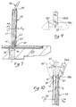
- Figure 7 illustrates a side view of the grinding worm 54 rotating about the grinding worm axis of rotation Z w in the direction of arrow A5, and grinding the teeth of the face gear 112.
- the dressing tool 56 is shown contacting the grinding worm 54 on a top surface thereof, but may be positioned to contact the surface of the grinding worm 54 along any portion thereof, except, obviously, where the grinding worm 54 is contacting the teeth of the face gear 112.
- the prior art teeth of the hob 25 were dressed with a double convex dressing spur tooth 47 ( Figure 4) and, consequently, the conventional hob teeth 30 ( Figure 3) were not accurately formed. Additionally, the conventional hob teeth 30 were only dressed before or after a cutting procedure and, thus, were not accurately maintained during the machining process.
- the presently preferred grinding worm 54 does not cut or machine the face gear 112 (as does the conventional hob) but, rather, precision grinds the face gear 112 after the face gear 112 has been case hardened, for example.
- the hob 25 of the prior art cannot operate to precision grind a case-hardened face gear.
- a single continuous grinding worm gap 67 passes over each of the teeth of the face gear 112.
- the single continuous grinding worm gap 67 forms a first grinding worm tooth 61, a second grinding worm tooth 63, and a third grinding worm tooth 65.
- the three grinding worm teeth 61, 63, 65 are shown operating on a first face gear tooth 38, a second face gear tooth 41, and a third face gear tooth 43.
- the dressing tool 56 forms the teeth of the grinding worm 54 into the teeth of a simulated spur pinion 73, for subsequent application and grinding of the teeth of the face gear 112.
- the grinding worm 54 is shown having first, second, and third grinding worm teeth 61, 63, and 65, other embodiments of the grinding worm 54 may comprise fewer or greater teeth.
- the alternative grinding worm 74 shown in Figure 8 comprises a single continuous grinding worm gap 81 and at least five grinding worm teeth 76.
- the alternative grinding worm 74 is shown precision grinding the teeth of a face gear 112.
- the grinding worm 54 ( Figure 7) of the presently preferred embodiment conprises a complex surface, which is suitable for accurately generating the teeth of a case-hardened face gear 112.
- the surface of the grinding worm 54 is complex, this surface can be generated automatically through either of two types of inventive dressing procedures.
- the procedure illustrated in Figures 9 and 10 comprises a simulation of tooth meshing between the dressing tool 56a and the spur pinion 73.
- This procedure is the subject of WO97/39856, filed on April 23, 1996 and entitled Apparatus For Precision Grinding Face Gears.
- the spur pinion 73 shown in phantom in Figure 9 is the actual spur pinion which will mesh with the face gear 112 during normal operation.
- the dressing tool 56a of the co-pending application comprises a double concave surface, which is an internal sector of the spur pinion 73.
- the dressing tool tooth 58a is shaped to snugly fit between two teeth of the spur pinion 73.
- the dressing tool tooth 58a has an involute profile of an internal sector of the spur pinion 73.
- This dressing tool tooth 58a is shown in Figure 10 fitting between a first grinding worm tooth 70 and a second grinding worm tooth 72. Since the dressing tool tooth 58a comprises an involute profile of the spur pinion 73, the dressing tool 56a tends to approximately maintain the shape of the grinding worm 54 to a shape similar to that of the spur pinion 73. Consequently, grinding of the face gear teeth 112 by the grinding worm 54 tends to prepare the teeth of the face gear 112 for eventual meshing with the teeth of the spur pinion 73.
- the dressing tool 56a axis of rotation Z t is located a distance E sw from the grinding worm axis of rotation Z w .
- Figure 10 illustrates movement of the dressing tool 56a along the single continuous grinding worm gap 67 of the grinding worm 54.
- the dressing tool tooth 58a enters the single continuous grinding worm gap 67 at an entry point 87, and begins contacting a portion of the second grinding worm tooth 72.
- the dressing tool 56a travels along the single continuous grinding worm gap 67 to an intermediate position, where the dressing tool 56a contacts both the first grinding worm tooth 70 and the second grinding worm tooth 72.
- the dressing tool is shown at this intermediate position in phantom with the reference number 87.
- the dressing tool 56a continues to move in the direction of the arrow A7 about the dressing tool axis of rotation Z t ( Figure 5).
- the dressing tool exits the single continuous grinding worm gap 67 at the exit point 89, where the dressing tool is shown in phantom with the reference number 90 contacting only the outer portion of the first grinding worm tooth 70.
- the dressing tool 56a preferably moves through the entire single continuous grinding worm gap 67 with approximately three rotations of the grinding worm 54.
- the dressing tool 56a of Figures 9 and 10 overcomes problems associated with the prior art, the dressing tool 56 ( Figure 7) of the present invention is considered to be even better. It has been discovered that a problem of undercutting can occur with the dressing tool 56a when a number of teeth 201 of the spur pinion 73 is less than 24, for example. More particularly, with reference to Figure 10, when a number of teeth 201 of the spur pinion 73 is small, the relative size of each tooth 201 is large. Accordingly, when the number of teeth 201 of the spur pinion 73 is small, the dimensions of the dressing tool tooth 58a are relatively large.
- the tip of the dressing tool tooth 58a tends to cut too much into the grinding worm 54 at the positions 87 and 89, corresponding to the extreme angular orientations of the dressing tool 56a, 90, respectively, as illustrated in Figure 10. Since the dressing tool 56a is configured as the compliment of the spur pinion 73, large angular orientations of the dressing tool 56a unavoidably result in undercutting as the dressing tool 56a exactly follows the angular motion of the spur pinion 73.
- the presently preferred dressing tool 56 (Figure 7), however, does not rely on exactly following the angular motion of the spur pinion 73. Instead, generally speaking, the dressing tool 56 traces the envelope formed buy the spur pinion 73 ( Figure 9) on the grinding worm 54 as a grinding worm 54 rotates.
- the dressing tool 56 is not a compliment of the spur pinion 73 but, rather, comprises a plane which is controlled to always be in tangency with the spur pinion 73.
- the dressing tool 56 can effectively dress the grinding wheel 54 without following the angular motion of the spur pinion 73, because two independent variables of motion provide the required freedom for maintaining tangency conditions of the dressing tool 56 with the spur pinion 73, without exactly following the angular motion of the spur pinion 73.
- the dressing procedure associated with the dressing tool 56a is a function of only one variable, which is the angular orientation of the dressing tool 56a as the dressing tool 56a moves along the arrow A7 ( Figure 10).
- This one variable-enveloping process has difficulties in meeting special topological modification requirements on the spur pinion tooth 201 surface, which must generally be expressed using two independent variables.
- the two independent-variable approach utilized by the dressing tool 56 of the present invention provides for the possibility of introducing any desired topological modifications to the grinding worm 54 and, consequently, to the face gear teeth 114 and 116 ( Figure 8).
- the grinding worm 54 of the present invention is thus generated by two-parametric enveloping of a family of surfaces.
- the generating plane 58 of the dressing tool 56 is in theoretical line tangency with the spur pinion 73, and is in theoretical point contact with both the face gear 112 and the grinding worm 54.
- the grinding worm 54 generated by the presently preferred embodiment will grind the face gear 112 with a true conjugate tooth profile of the spur pinion 73, thus providing smooth motion transmission when meshing with the pinion.
- the two-parametric design of the dressing process of the presently preferred embodiment is not limited by undercutting problems associated with small numbers of spur pinion teeth 201 (for example, 24 to 28 spur pinion teeth 201) but, of course, this preferred dressing technique may still be affected by undercutting in the design of the spur pinion 73 itself.
- the two-parametric enveloping process allows for introduction of predesigned modifications to the grinding worm 54 along two directions on the thread surface, which can then be passed to the face gear teeth 114, 116 during grinding. Such topological modifications, if well designed, can produce parabolic-type transmission errors in the gear set to absorb linear-type transmission errors which are caused by machining and assembly inaccuracies.
- the dressing tool 56 is shown in schematic form superimposed on the face gear 112.
- the spur pinion 73 shown in phantom, is also superimposed on the face gear 112 for illustrative purposes.
- the dressing tool 56 is moved with a complex motion that is generally designed to have the tip 58 trace the outline of the spur 73 while contacting and grinding the worm gear 54.
- the motion of the dressing tool 56 can be represented or controlled by two independent variables ⁇ and S , as described below.
- the teeth of the face gear 112 are generated as one-parametric enveloping of the spur pinion surface ⁇ s , with the one-parametric being the rotation of the spur pinion 73.
- two surfaces ⁇ s and ⁇ g are in line contact.
- the grinding process can be explained by adding a grinding worm 54 to the imaginary mesh of the spur pinion 73 and the face gear 112.
- the dressing tool 56 comprises a dressing disc having a flat surface 58, which is placed in tangency with the profile of the spur pinion 73 at any instant.
- this movement of the dressing tool 56 can be represented by two variables ⁇ and S.
- ⁇ is defined as an angle formed between the two lines 242 and 244.
- Line 242 is parallel to the planar face 58 of the dressing tool 56 and is perpendicular to the rotational axis of the spur pinion 73.
- Line 244 is defined as passing through a line of shortest distance between the rotational axis of the spur pinion 73 and the rotational axis of the grinding wheel 54.
- the variable S is defined as a distance from the face 58 of the dressing tool 56 to a plane that is parallel to the face 58 of the dressing tool 56 and passing through the rotational axis of the spur pinion 73.
- the variable r b is the base radius of the spur pinion 73, and the variable ⁇ w is the angle of rotation of the grinding worm 54.
- the above Equation 5 yields a definite angle of rotation ⁇ w of the grinding worm 54.
- the dressing tool 56 and the grinding worm 54 move relatively to one another continuously following Equation 5.
- the movements are performed back and forth for contacting the threads of the grinding worm 54.
- the dressing tool 56 has the following meshing conditions: (1) the dressing tool 56 is in line tangency with the spur pinion 73, (2) the dressing tool 56 is in point contact with the face gear 112, and (3) the dressing tool 56 is in point contact with the grinding worm 54 with the point of contact being the intersection of the theoretical contact line of the ⁇ variable and that of the S variable.
- Figure 12 illustrates three different positions of the dressing tool 56, with the latter two orientations, 262 and 264 shown in phantom.
- the angle ⁇ 1 and the distance S 1 defining the orientation of the dressing tool 56
- the angle ⁇ 2 and the distance S 2 defining the position of the dressing tool 262.
- the angle ⁇ 3 and the angle S 3 define the position of the dressing tool 264.
- the angle of rotation ⁇ and the distance S of the dressing tool are determined by Equation 5. For each specific set of values for ⁇ and S , the angle of rotation of the grinding wheel 54 is changed. Additionally, changing either value ⁇ or S , independently, will also change the angle of rotation of the grinding worm 54.
- Figure 13 illustrates an apparatus 280 that is suitable for moving the dressing tool 56 along the surface of the grinding worm 54.
- the x-axis 282 is positive in the right direction
- the z-axis 284 is positive in the left direction
- the y-axis 286 is positive in the upward direction, relative to the page on which Figure 13 is shown.
- the arm 290 is moveable above the base 292 for achieving x-axis movement
- the arm 294 is moveable above the base 292 for achieving z-axis movement.
- An arm 298 is connected to the arm 290, and is adapted for achieving y-axis movement.
- the head stock spindle 300 is rotatable about its rotational axis, as is the cylinder 302.
- the grinding worm 54 to be dressed is mounted on the head stock spindle 300 with motion in the direction of the arrow A8 simulating the angle of rotation of the grinding worm 54.
- the dressing tool 56 is mounted on the tool spindle 302 with motion in the direction of the arrow A9 simulating the angle ⁇ , and the linear variable S being simulated with the combination of the x, y and z movements of the arms 290, 294, and 298.
- the dressing tool 56 of the present invention is especially advantageous when used in conunction with spur pinions having teeth fewer than 24-28.
- spur pinions are quite often desired in gear set designs with high reduction ratios. It is estimated that well over one half of face gear applications fall into this category.
- the two parametric enveloping process is especially suitable for applications requiring topological modifications on the face gear 112 tooth surface. Examples of such applications include specific tooth deviations purposefully introduced in the roughing process before heat treatment to compensate for distortions during heat treatment to thereby provide an even amount of finished grinding stocks and hardened case depth, and well designed tooth deviations introduced so that the contact pattern with the mating spur pinion can be localized and the shift of pattern under load can be controlled in size and direction.
- the tooth surface can also be topologically modified with a two-pair metric enveloping process to provide prescribed parabolic-types of transmission errors that can absorb linear-type transmission errors induced by manufacturing errors and structure deflections. This tooth surface modification can substantially reduce the level of noise generated at the gear mesh, and is especially applicable to high speed applications. Additionally, the flat surface 58 of the dressing tool 56 renders the manufacture of the dressing tool 56 relatively simple and accurate.
- the grinding worm 54 and dressing tool 56 combination of the present invention may be used to fabricate high quality straight faced gears, as well as helical faced gears. These gears may be treated to high hardness levels and precision ground by the grinding worm 54 and dressing tool 56 to thereby accommodate high power applications.
- Face gears of the prior art are generally suitable for control gears only. Face gears ground to AGMA class 10 quality or higher, using the present invention, can be used in high speed and high load applications wherever beveled gears, which have a more complex geometry, are utilized. Such applications include angular drives involving intersecting axes and crossed axis drive shafts. The potential cost savings of using face gears in lieu of beveled gears is substantial.
- face gears are easier to install, since establishing the pinion and gear mounting distance is less difficult than with beveled gears.
- face gears possess configurational advantages over other gears, such as the capability of driving two face gears from one pinion when the face gears are installed on opposite sides of the pinion. Accordingly, a dual feed drive for additional accessory equipment usage or a split of input engine torque may be utilized to provide lighter intermediate power paths. The split torque drive train may then be recombined prior to the final output. This split torque concept can provide substantial weight savings when applied to helicopter transmissions, for example.
Claims (5)
- Präzisionsschleifvorrichtung für ein einsatzgehärtetes Tellerrad (112), umfassend:Ein einsatzgehärtetes Tellerrad (112), das passend zum Eingriff in eine Geradstimritzeloberfläche eines Geradstimritzels geschliffen werden soll, eine kurvenförmige Linie, die als eine Linie entlang der Geradstirnritzeloberfläche definiert ist, die allgemein parallel zu einer Rotationsachse des Geradstimritzels verläuft;eine Schleifschnecke (54), die in einer im Wesentlichen normalen Orientierung zum einsatzgehärteten Tellerrad angeordnet ist, wobei die Schleifschnecke (54) eine Schleifschneckenoberfläche (55) aufweist, die angepasst ist, das einsatzgehärtete Tellerrad (112) zu kontaktieren und zu schleifen;
undein Richtwerkzeug (56) mit einer flachen Oberfläche, dadurch gekennzeichnet, dass das Richtwerkzeug, das angepasst ist die Schleifschneckenoberfläche zu kontaktieren und sich an dieser entlang zu bewegen, während die Schleifschnecke (54) das einsatzgehärtete Tellerrad (112) schleift und das, gleichzeitig, angepasst ist sich entlang der kurvenförmigen Linie zu bewegen aber diese nicht zu schneiden, eine planare Oberfläche aufweist, die die Schleifschnecke mit einer Hüllkurve abrichtet, die vom Richtwerkzeug generiert wird sowie es die Schleifschnecke berührt und sich der Hüllkurve nähert, die es generieren würde, wenn es sich über die Oberfläche des besagten Geradstirnritzels bewegen würde. - Vorrichtung nach Anspruch 1, dadurch gekennzeichnet, dass die Schleifschnecke (54) eine Schleifschnecken-Rotationsachse (Zw) umfasst und, dass sich das Richtwerkzeug sowohl entlang der kurvenförmigen Linie als auch der Schleifschneckenoberfläche bewegt sowie die Schleifschnecke um die Schleifschneckenrotationsachse rotiert.
- Vorrichtung nach Anspruch 1, dadurch gekennzeichnet, dass besagte Geradstimritzeloberfläche Geradstimritzelzähne einschließt.
- Vorrichtung nach Anspruch 3, dadurch gekennzeichnet, dass das einsatzgehärtete Tellerrad eine Vielheit von Zähnen (114) umfasst, die angepasst sind in die Geradstimritzelzähne einzugreifen, wobei sich jeder der Zähne radial ab einem Zentrum des einsatzgehärteten Tellerrads (112) erstreckt und entlang einem Außenumfang des einsatzgehärteten Tellerrads positioniert ist.
- Verfahren zum Präzisionsschleifen einer Vielheit von Tellerradzähnen (114) auf einem Tellerrad (112), wobei die Tellerradzähne (114) angepasst sind in ein Geradstirnritzel einzugreifen, eine kurvenförmige Linie, als eine Linie entlang der Geradstimritzeloberfläche definiert ist, die allgemein parallel zur Rotationsachse des Geradstimritzels verläuft, das Verfahren folgende Schritte aufweist:Bereitstellen einer Schleifschnecke (54), wobei die Schleifschnecke eine Rotationsachse (Zw) aufweist;Rotieren der Schleifschnecke;In Kontakt bringen der rotierenden Schleifschnecke mit dem Tellerrad (112), um dadurch die Vielheit der Tellerradzähne (114) mit Präzision zu schleifen;Bereitstellen eines Richtwerkzeugs (56) mit einer planaren Oberfläche; undgekennzeichnet durchIn Kontakt Bringen der planaren Oberfläche des Richtwerkzeugs mit der rotierenden Schleifschnecke, um dadurch die rotierende Schleifschnecke abzurichten, während die Schleifschnecke das einsatzgehärtete Tellerrad schleift, wobei sich das Richtwerkzeug entlang der kurvenförmigen Linie bewegt aber diese nicht schneidet, eine Hüllkurve vom Richtwerkzeug generiert wird sowie das Richtwerkzeug die rotierende Schleifschnecke schleift, indem es sich einer Hüllkurve annähert, die das Richtwerkzeug generieren würde, wenn sich das Richtwerkzeug über eine Oberfläche des besagten Geradstirnritzels bewegen würde.
Applications Claiming Priority (3)
| Application Number | Priority Date | Filing Date | Title |
|---|---|---|---|
| US680932 | 1996-07-16 | ||
| US08/680,932 US5823857A (en) | 1996-04-23 | 1996-07-16 | Apparatus and method for precision grinding of face gears |
| PCT/US1997/011979 WO1998002268A1 (en) | 1996-07-16 | 1997-07-09 | Apparatus and method for improved precision grinding of face gears |
Publications (3)
| Publication Number | Publication Date |
|---|---|
| EP0921886A1 EP0921886A1 (de) | 1999-06-16 |
| EP0921886A4 EP0921886A4 (de) | 2002-05-02 |
| EP0921886B1 true EP0921886B1 (de) | 2006-04-05 |
Family
ID=24733102
Family Applications (1)
| Application Number | Title | Priority Date | Filing Date |
|---|---|---|---|
| EP97933357A Expired - Lifetime EP0921886B1 (de) | 1996-07-16 | 1997-07-09 | Apparat und verfahren zum präzisionsschleifen von kronenrädern |
Country Status (7)
| Country | Link |
|---|---|
| US (1) | US5823857A (de) |
| EP (1) | EP0921886B1 (de) |
| AU (1) | AU3656297A (de) |
| DE (1) | DE69735631T2 (de) |
| IL (1) | IL127975A (de) |
| TR (1) | TR199900131T2 (de) |
| WO (1) | WO1998002268A1 (de) |
Cited By (1)
| Publication number | Priority date | Publication date | Assignee | Title |
|---|---|---|---|---|
| CN103692026A (zh) * | 2014-01-16 | 2014-04-02 | 哈尔滨理工大学 | 基于平面砂轮端面的正交面齿轮磨削加工方法 |
Families Citing this family (33)
| Publication number | Priority date | Publication date | Assignee | Title |
|---|---|---|---|---|
| US6146253A (en) * | 1996-04-23 | 2000-11-14 | Mcdonnell Douglas Helicopter Company | Apparatus and method for precision grinding face gear |
| US5967883A (en) * | 1996-12-28 | 1999-10-19 | Namu Co., Ltd. | Working apparatus provided with rotary table for mass-production of gears |
| DE19734793A1 (de) * | 1997-08-11 | 1999-02-18 | Kopp Werkzeugmasch Gmbh | Schleifscheibe |
| AU3106899A (en) * | 1998-03-18 | 1999-10-11 | Gleason Works, The | Threaded grinding wheel and method of dressing |
| US6390894B1 (en) * | 1998-12-21 | 2002-05-21 | Derlan Aerospace Canada | Face gear manufacturing method and apparatus |
| US6205879B1 (en) * | 1999-06-28 | 2001-03-27 | Visteon Global Technologies, Inc. | Helical and spur gear drive with double crowned pinion tooth surfaces and conjugated gear tooth surfaces |
| DE10054795A1 (de) * | 2000-11-04 | 2002-06-13 | Reishauer Ag | Verzahnungsbearbeitung doppelseitig verzahnter Kronenräder |
| US6585457B2 (en) * | 2000-12-27 | 2003-07-01 | Delphi Technologies, Inc. | Abrasive generation of non-metallic gear |
| US6602115B2 (en) | 2001-01-03 | 2003-08-05 | The Boeing Company | Tool and method for precision grinding of a conical face gear that meshes with a conical involute pinion |
| EP1312445B1 (de) * | 2001-11-14 | 2008-09-03 | Klingelnberg AG | Verfahren, Vorrichtung und Software zum Profilschleifen und gleichzeitigen abrichten des Schleifwerkzeuges |
| EP1325792B1 (de) * | 2002-01-08 | 2011-02-16 | The Boeing Company | Werkzeug und Verfahren zum Präzisionsschleifen eines konischen Kronrades das in ein evolventförmiges Kegelritzel eingreift |
| US7191521B2 (en) * | 2003-02-07 | 2007-03-20 | American Axle & Manufacturing, Inc. | Advanced geometry of skew and straight bevel gears produced by forging |
| US20060090340A1 (en) * | 2004-11-03 | 2006-05-04 | Yakov Fleytman | Method of generation of face enveloping gears |
| US7267300B2 (en) * | 2005-02-25 | 2007-09-11 | The Boeing Company | Aircraft capable of vertical and short take-off and landing |
| US7527548B2 (en) * | 2005-03-10 | 2009-05-05 | Sikorsky Aircraft Corporation | System and method for precision machining of high hardness gear teeth and splines |
| DE102007020479B4 (de) * | 2007-04-27 | 2010-10-21 | Kapp Gmbh | Verfahren und Schleifmaschine zum Profilieren eines Schleifwerkzeugs |
| JP5000459B2 (ja) * | 2007-11-14 | 2012-08-15 | 本田技研工業株式会社 | ハイポイドギヤの噛合位置調整方法 |
| GB0817775D0 (en) | 2008-09-29 | 2008-11-05 | Goodrich Actuation Systems Ltd | Actuator |
| US9108258B2 (en) * | 2009-08-03 | 2015-08-18 | The Gleason Works | Method and tool for manufacturing face gears |
| US9132493B2 (en) | 2010-01-29 | 2015-09-15 | The Gleason Works | Continuous method for manufacturing face gears |
| JP5748582B2 (ja) * | 2011-07-12 | 2015-07-15 | 三菱重工業株式会社 | ねじ状工具の製作方法 |
| CN103128385B (zh) * | 2011-11-24 | 2015-09-09 | 深圳市兆威机电有限公司 | 一种注塑面齿轮电极及注塑面齿轮的加工方法 |
| JP5854792B2 (ja) * | 2011-11-25 | 2016-02-09 | 三菱重工業株式会社 | 鼓形歯車状砥石のドレッシング方法及びディスク形ドレッサ |
| US8801503B2 (en) * | 2012-06-19 | 2014-08-12 | Gleason Cutting Tools Corporation | Grinding machine with multi-spindle grinding head |
| DE102013015232A1 (de) * | 2013-09-13 | 2015-03-19 | Liebherr-Verzahntechnik Gmbh | Verfahren zur Herstellung eines Abrichtwerkzeuges, Abrichtwerkzeug und Verfahren zum Abrichten einer Schleifschnecke |
| CN104759702B (zh) * | 2015-03-31 | 2017-01-11 | 北京工业大学 | 圆柱齿轮的拓扑修形方法 |
| DE102016004112A1 (de) * | 2016-04-05 | 2017-10-05 | Gleason-Pfauter Maschinenfabrik Gmbh | Verfahren zur erzeugung einer abtragung an einer zahnstirnkante und dazu ausgelegte vorrichtung |
| CN208692333U (zh) * | 2017-06-16 | 2019-04-05 | 沟口初子 | 胸罩 |
| CN108188494A (zh) * | 2017-12-22 | 2018-06-22 | 重庆文理学院 | 一种加工端面齿轮的铣刀及方法 |
| TWI659165B (zh) * | 2018-08-09 | 2019-05-11 | 正修學校財團法人正修科技大學 | 製造具有預設的二階或四階傳動誤差之點接觸正弦面齒輪傳動機構的方法 |
| DE102019107899A1 (de) * | 2019-03-27 | 2020-10-01 | WELTER zahnrad GmbH | Servogetriebe, Servostelleinheit mit einem Servogetriebe und Verfahren zum Herstellen eines Servogetriebes |
| CN112643143B (zh) * | 2020-11-13 | 2022-05-06 | 重庆大学 | 一种磨削面齿轮的鼓形蜗杆砂轮廓形设计方法 |
| CN114211057B (zh) * | 2021-11-30 | 2023-09-26 | 西北工业大学 | 一种基于圆柱齿轮数控磨齿机磨削非正交面齿轮的方法 |
Family Cites Families (11)
| Publication number | Priority date | Publication date | Assignee | Title |
|---|---|---|---|---|
| US2304586A (en) * | 1940-12-14 | 1942-12-08 | Fellows Gear Shaper Co | Hob for generating crown gears |
| US4518287A (en) * | 1982-07-07 | 1985-05-21 | Western Gear Corporation | Method of face mill generation of spiral bevel gears with integral central structure and resulting product |
| DD226818A1 (de) * | 1984-09-07 | 1985-09-04 | Wtz Getriebe & Kupplungen Veb | Vorrichtung zum anstellen des werkstueckes beim schleifen von aussenverzahnungen |
| DE3819320A1 (de) * | 1987-06-13 | 1988-12-29 | Zahnradfabrik Friedrichshafen | Schleifmaschine zum kontinuierlichen waelzschleifen von zahnraedern |
| NL8800472A (nl) * | 1988-02-24 | 1989-09-18 | Hankamp Bv | Werkwijze voor het vervaardigen en/of nabewerken van kroonwielen. |
| US5135442A (en) * | 1990-02-12 | 1992-08-04 | Lucas Western, Inc. | Gear arrangement for transmitting torque through an angle |
| US5178028A (en) * | 1990-09-27 | 1993-01-12 | Lucas Western, Inc. | Offset face gear transmission |
| NL9002611A (nl) * | 1990-11-29 | 1992-06-16 | Crown Gear Bv | Gereedschap voor het vervaardigen van kroonwielen, alsmede werkwijze voor het vervaardigen van een dergelijk gereedschap. |
| US5411431A (en) * | 1991-01-09 | 1995-05-02 | Crown Gear, B.V. | Method for crown gear grinding by generation |
| US5233886A (en) * | 1992-05-26 | 1993-08-10 | Lucas Western, Inc. | Increased capacity face gear arrangement for transmitting torque through an angle and to a plurality of power extraction paths |
| US5289815A (en) * | 1993-06-21 | 1994-03-01 | The Gleason Works | Method of dressing a threaded grinding wheel |
-
1996
- 1996-07-16 US US08/680,932 patent/US5823857A/en not_active Expired - Lifetime
-
1997
- 1997-07-09 AU AU36562/97A patent/AU3656297A/en not_active Abandoned
- 1997-07-09 DE DE69735631T patent/DE69735631T2/de not_active Expired - Lifetime
- 1997-07-09 IL IL12797597A patent/IL127975A/en not_active IP Right Cessation
- 1997-07-09 TR TR1999/00131T patent/TR199900131T2/xx unknown
- 1997-07-09 WO PCT/US1997/011979 patent/WO1998002268A1/en active IP Right Grant
- 1997-07-09 EP EP97933357A patent/EP0921886B1/de not_active Expired - Lifetime
Cited By (1)
| Publication number | Priority date | Publication date | Assignee | Title |
|---|---|---|---|---|
| CN103692026A (zh) * | 2014-01-16 | 2014-04-02 | 哈尔滨理工大学 | 基于平面砂轮端面的正交面齿轮磨削加工方法 |
Also Published As
| Publication number | Publication date |
|---|---|
| EP0921886A1 (de) | 1999-06-16 |
| US5823857A (en) | 1998-10-20 |
| EP0921886A4 (de) | 2002-05-02 |
| AU3656297A (en) | 1998-02-09 |
| IL127975A0 (en) | 1999-11-30 |
| TR199900131T2 (xx) | 2000-08-21 |
| IL127975A (en) | 2001-11-25 |
| WO1998002268A1 (en) | 1998-01-22 |
| DE69735631D1 (de) | 2006-05-18 |
| DE69735631T2 (de) | 2007-01-11 |
Similar Documents
| Publication | Publication Date | Title |
|---|---|---|
| EP0921886B1 (de) | Apparat und verfahren zum präzisionsschleifen von kronenrädern | |
| US6146253A (en) | Apparatus and method for precision grinding face gear | |
| EP0573528B1 (de) | Wälzverfahren zum Herstellen von Kegel- und Hypoidzahnrädern | |
| US4910922A (en) | Method of grinding the teeth of bevel gears having longitudinally curved teeth | |
| KR100634061B1 (ko) | 기어를 다듬질하는 방법 및 기어 | |
| JP2994755B2 (ja) | ねじ型砥石車の目直し方法 | |
| WO1994016245A1 (en) | Gear tooth topological modification | |
| JPH0775916A (ja) | 内歯を付けられた工具によって歯車形の工作物の歯面を精密加工する方法及びこの工具を仕上げ加工する方法並びにこの仕上げ加工に適した仕上げ車 | |
| US5651721A (en) | Method for the precision working of gears with an internally toothed tool, which for dressing remains in the precision working machine | |
| US5255475A (en) | Tool for grinding the teeth of bevel gears having longitudinally curved teeth | |
| EP1027464B1 (de) | Verfahren zum schmieden von kronrädern | |
| US4378660A (en) | Method of and means for grinding pairs of gear wheels as spiral or curved toothed bevel gear wheels | |
| US5901454A (en) | Method of meshing gears | |
| EP0693016B1 (de) | Verfahren zur herstellung eines kronenrades | |
| GB1593225A (en) | Method of and means for grinding pairs of gear wheels as spiral or curved toothed bevel gear wheels | |
| DE4231021A1 (de) | Verfahren und Vorrichtung zur schraubwälzenden, spanenden Bearbeitung von Evolventenzahnflanken | |
| CN109702276B (zh) | 用于加工锥齿轮工件的齿侧面的方法 | |
| GB2155372A (en) | Improving or forming curved tooth surfaces | |
| US3504565A (en) | Spur gear system of crossed axes and method of manufacturing same | |
| US20220402055A1 (en) | Method of manufacturing a toothed bevel honing tool for honing a toothed bevel workpiece, a toothed bevel honing tool and method of honing bevel gears | |
| Wright et al. | Basic honing and advanced free-form honing | |
| EP1325792B1 (de) | Werkzeug und Verfahren zum Präzisionsschleifen eines konischen Kronrades das in ein evolventförmiges Kegelritzel eingreift | |
| JPH03184719A (ja) | 鼓形ウォーム修正歯切用ピニオンカッター |
Legal Events
| Date | Code | Title | Description |
|---|---|---|---|
| PUAI | Public reference made under article 153(3) epc to a published international application that has entered the european phase |
Free format text: ORIGINAL CODE: 0009012 |
|
| 17P | Request for examination filed |
Effective date: 19990210 |
|
| AK | Designated contracting states |
Kind code of ref document: A1 Designated state(s): CH DE FI FR GB GR IT LI NL |
|
| A4 | Supplementary search report drawn up and despatched |
Effective date: 20020319 |
|
| AK | Designated contracting states |
Kind code of ref document: A4 Designated state(s): CH DE FI FR GB GR IT LI NL |
|
| 17Q | First examination report despatched |
Effective date: 20020830 |
|
| GRAP | Despatch of communication of intention to grant a patent |
Free format text: ORIGINAL CODE: EPIDOSNIGR1 |
|
| GRAS | Grant fee paid |
Free format text: ORIGINAL CODE: EPIDOSNIGR3 |
|
| GRAA | (expected) grant |
Free format text: ORIGINAL CODE: 0009210 |
|
| AK | Designated contracting states |
Kind code of ref document: B1 Designated state(s): CH DE FI FR GB GR IT LI NL |
|
| PG25 | Lapsed in a contracting state [announced via postgrant information from national office to epo] |
Ref country code: NL Free format text: LAPSE BECAUSE OF FAILURE TO SUBMIT A TRANSLATION OF THE DESCRIPTION OR TO PAY THE FEE WITHIN THE PRESCRIBED TIME-LIMIT Effective date: 20060405 Ref country code: LI Free format text: LAPSE BECAUSE OF FAILURE TO SUBMIT A TRANSLATION OF THE DESCRIPTION OR TO PAY THE FEE WITHIN THE PRESCRIBED TIME-LIMIT Effective date: 20060405 Ref country code: FI Free format text: LAPSE BECAUSE OF FAILURE TO SUBMIT A TRANSLATION OF THE DESCRIPTION OR TO PAY THE FEE WITHIN THE PRESCRIBED TIME-LIMIT Effective date: 20060405 Ref country code: CH Free format text: LAPSE BECAUSE OF FAILURE TO SUBMIT A TRANSLATION OF THE DESCRIPTION OR TO PAY THE FEE WITHIN THE PRESCRIBED TIME-LIMIT Effective date: 20060405 |
|
| REG | Reference to a national code |
Ref country code: GB Ref legal event code: FG4D |
|
| REG | Reference to a national code |
Ref country code: CH Ref legal event code: EP |
|
| REF | Corresponds to: |
Ref document number: 69735631 Country of ref document: DE Date of ref document: 20060518 Kind code of ref document: P |
|
| PGFP | Annual fee paid to national office [announced via postgrant information from national office to epo] |
Ref country code: NL Payment date: 20060724 Year of fee payment: 10 |
|
| NLV1 | Nl: lapsed or annulled due to failure to fulfill the requirements of art. 29p and 29m of the patents act | ||
| REG | Reference to a national code |
Ref country code: CH Ref legal event code: PL |
|
| ET | Fr: translation filed | ||
| PLBE | No opposition filed within time limit |
Free format text: ORIGINAL CODE: 0009261 |
|
| STAA | Information on the status of an ep patent application or granted ep patent |
Free format text: STATUS: NO OPPOSITION FILED WITHIN TIME LIMIT |
|
| 26N | No opposition filed |
Effective date: 20070108 |
|
| PG25 | Lapsed in a contracting state [announced via postgrant information from national office to epo] |
Ref country code: GR Free format text: LAPSE BECAUSE OF FAILURE TO SUBMIT A TRANSLATION OF THE DESCRIPTION OR TO PAY THE FEE WITHIN THE PRESCRIBED TIME-LIMIT Effective date: 20060706 |
|
| REG | Reference to a national code |
Ref country code: FR Ref legal event code: PLFP Year of fee payment: 20 |
|
| PGFP | Annual fee paid to national office [announced via postgrant information from national office to epo] |
Ref country code: GB Payment date: 20160727 Year of fee payment: 20 Ref country code: DE Payment date: 20160726 Year of fee payment: 20 Ref country code: IT Payment date: 20160722 Year of fee payment: 20 |
|
| PGFP | Annual fee paid to national office [announced via postgrant information from national office to epo] |
Ref country code: FR Payment date: 20160726 Year of fee payment: 20 |
|
| REG | Reference to a national code |
Ref country code: DE Ref legal event code: R071 Ref document number: 69735631 Country of ref document: DE |
|
| REG | Reference to a national code |
Ref country code: GB Ref legal event code: PE20 Expiry date: 20170708 |
|
| PG25 | Lapsed in a contracting state [announced via postgrant information from national office to epo] |
Ref country code: GB Free format text: LAPSE BECAUSE OF EXPIRATION OF PROTECTION Effective date: 20170708 |