EP0918155A2 - Soupape d'injection de combustible - Google Patents
Soupape d'injection de combustible Download PDFInfo
- Publication number
- EP0918155A2 EP0918155A2 EP98121592A EP98121592A EP0918155A2 EP 0918155 A2 EP0918155 A2 EP 0918155A2 EP 98121592 A EP98121592 A EP 98121592A EP 98121592 A EP98121592 A EP 98121592A EP 0918155 A2 EP0918155 A2 EP 0918155A2
- Authority
- EP
- European Patent Office
- Prior art keywords
- fuel
- injection port
- valve
- valve body
- nozzle
- Prior art date
- Legal status (The legal status is an assumption and is not a legal conclusion. Google has not performed a legal analysis and makes no representation as to the accuracy of the status listed.)
- Granted
Links
Images


Classifications
-
- F—MECHANICAL ENGINEERING; LIGHTING; HEATING; WEAPONS; BLASTING
- F02—COMBUSTION ENGINES; HOT-GAS OR COMBUSTION-PRODUCT ENGINE PLANTS
- F02M—SUPPLYING COMBUSTION ENGINES IN GENERAL WITH COMBUSTIBLE MIXTURES OR CONSTITUENTS THEREOF
- F02M61/00—Fuel-injectors not provided for in groups F02M39/00 - F02M57/00 or F02M67/00
- F02M61/16—Details not provided for in, or of interest apart from, the apparatus of groups F02M61/02 - F02M61/14
- F02M61/18—Injection nozzles, e.g. having valve seats; Details of valve member seated ends, not otherwise provided for
- F02M61/1806—Injection nozzles, e.g. having valve seats; Details of valve member seated ends, not otherwise provided for characterised by the arrangement of discharge orifices, e.g. orientation or size
- F02M61/1846—Dimensional characteristics of discharge orifices
-
- F—MECHANICAL ENGINEERING; LIGHTING; HEATING; WEAPONS; BLASTING
- F02—COMBUSTION ENGINES; HOT-GAS OR COMBUSTION-PRODUCT ENGINE PLANTS
- F02M—SUPPLYING COMBUSTION ENGINES IN GENERAL WITH COMBUSTIBLE MIXTURES OR CONSTITUENTS THEREOF
- F02M61/00—Fuel-injectors not provided for in groups F02M39/00 - F02M57/00 or F02M67/00
- F02M61/16—Details not provided for in, or of interest apart from, the apparatus of groups F02M61/02 - F02M61/14
- F02M61/18—Injection nozzles, e.g. having valve seats; Details of valve member seated ends, not otherwise provided for
-
- F—MECHANICAL ENGINEERING; LIGHTING; HEATING; WEAPONS; BLASTING
- F02—COMBUSTION ENGINES; HOT-GAS OR COMBUSTION-PRODUCT ENGINE PLANTS
- F02B—INTERNAL-COMBUSTION PISTON ENGINES; COMBUSTION ENGINES IN GENERAL
- F02B17/00—Engines characterised by means for effecting stratification of charge in cylinders
- F02B17/005—Engines characterised by means for effecting stratification of charge in cylinders having direct injection in the combustion chamber
-
- F—MECHANICAL ENGINEERING; LIGHTING; HEATING; WEAPONS; BLASTING
- F02—COMBUSTION ENGINES; HOT-GAS OR COMBUSTION-PRODUCT ENGINE PLANTS
- F02B—INTERNAL-COMBUSTION PISTON ENGINES; COMBUSTION ENGINES IN GENERAL
- F02B23/00—Other engines characterised by special shape or construction of combustion chambers to improve operation
- F02B23/08—Other engines characterised by special shape or construction of combustion chambers to improve operation with positive ignition
- F02B23/10—Other engines characterised by special shape or construction of combustion chambers to improve operation with positive ignition with separate admission of air and fuel into cylinder
- F02B23/104—Other engines characterised by special shape or construction of combustion chambers to improve operation with positive ignition with separate admission of air and fuel into cylinder the injector being placed on a side position of the cylinder
-
- F—MECHANICAL ENGINEERING; LIGHTING; HEATING; WEAPONS; BLASTING
- F02—COMBUSTION ENGINES; HOT-GAS OR COMBUSTION-PRODUCT ENGINE PLANTS
- F02M—SUPPLYING COMBUSTION ENGINES IN GENERAL WITH COMBUSTIBLE MIXTURES OR CONSTITUENTS THEREOF
- F02M51/00—Fuel-injection apparatus characterised by being operated electrically
- F02M51/06—Injectors peculiar thereto with means directly operating the valve needle
- F02M51/061—Injectors peculiar thereto with means directly operating the valve needle using electromagnetic operating means
- F02M51/0625—Injectors peculiar thereto with means directly operating the valve needle using electromagnetic operating means characterised by arrangement of mobile armatures
- F02M51/0664—Injectors peculiar thereto with means directly operating the valve needle using electromagnetic operating means characterised by arrangement of mobile armatures having a cylindrically or partly cylindrically shaped armature, e.g. entering the winding; having a plate-shaped or undulated armature entering the winding
- F02M51/0671—Injectors peculiar thereto with means directly operating the valve needle using electromagnetic operating means characterised by arrangement of mobile armatures having a cylindrically or partly cylindrically shaped armature, e.g. entering the winding; having a plate-shaped or undulated armature entering the winding the armature having an elongated valve body attached thereto
-
- F—MECHANICAL ENGINEERING; LIGHTING; HEATING; WEAPONS; BLASTING
- F02—COMBUSTION ENGINES; HOT-GAS OR COMBUSTION-PRODUCT ENGINE PLANTS
- F02M—SUPPLYING COMBUSTION ENGINES IN GENERAL WITH COMBUSTIBLE MIXTURES OR CONSTITUENTS THEREOF
- F02M61/00—Fuel-injectors not provided for in groups F02M39/00 - F02M57/00 or F02M67/00
- F02M61/16—Details not provided for in, or of interest apart from, the apparatus of groups F02M61/02 - F02M61/14
- F02M61/162—Means to impart a whirling motion to fuel upstream or near discharging orifices
- F02M61/163—Means being injection-valves with helically or spirally shaped grooves
-
- F—MECHANICAL ENGINEERING; LIGHTING; HEATING; WEAPONS; BLASTING
- F02—COMBUSTION ENGINES; HOT-GAS OR COMBUSTION-PRODUCT ENGINE PLANTS
- F02M—SUPPLYING COMBUSTION ENGINES IN GENERAL WITH COMBUSTIBLE MIXTURES OR CONSTITUENTS THEREOF
- F02M61/00—Fuel-injectors not provided for in groups F02M39/00 - F02M57/00 or F02M67/00
- F02M61/16—Details not provided for in, or of interest apart from, the apparatus of groups F02M61/02 - F02M61/14
- F02M61/18—Injection nozzles, e.g. having valve seats; Details of valve member seated ends, not otherwise provided for
- F02M61/1806—Injection nozzles, e.g. having valve seats; Details of valve member seated ends, not otherwise provided for characterised by the arrangement of discharge orifices, e.g. orientation or size
-
- F—MECHANICAL ENGINEERING; LIGHTING; HEATING; WEAPONS; BLASTING
- F02—COMBUSTION ENGINES; HOT-GAS OR COMBUSTION-PRODUCT ENGINE PLANTS
- F02B—INTERNAL-COMBUSTION PISTON ENGINES; COMBUSTION ENGINES IN GENERAL
- F02B75/00—Other engines
- F02B75/12—Other methods of operation
- F02B2075/125—Direct injection in the combustion chamber for spark ignition engines, i.e. not in pre-combustion chamber
-
- Y—GENERAL TAGGING OF NEW TECHNOLOGICAL DEVELOPMENTS; GENERAL TAGGING OF CROSS-SECTIONAL TECHNOLOGIES SPANNING OVER SEVERAL SECTIONS OF THE IPC; TECHNICAL SUBJECTS COVERED BY FORMER USPC CROSS-REFERENCE ART COLLECTIONS [XRACs] AND DIGESTS
- Y02—TECHNOLOGIES OR APPLICATIONS FOR MITIGATION OR ADAPTATION AGAINST CLIMATE CHANGE
- Y02T—CLIMATE CHANGE MITIGATION TECHNOLOGIES RELATED TO TRANSPORTATION
- Y02T10/00—Road transport of goods or passengers
- Y02T10/10—Internal combustion engine [ICE] based vehicles
- Y02T10/12—Improving ICE efficiencies
-
- Y—GENERAL TAGGING OF NEW TECHNOLOGICAL DEVELOPMENTS; GENERAL TAGGING OF CROSS-SECTIONAL TECHNOLOGIES SPANNING OVER SEVERAL SECTIONS OF THE IPC; TECHNICAL SUBJECTS COVERED BY FORMER USPC CROSS-REFERENCE ART COLLECTIONS [XRACs] AND DIGESTS
- Y10—TECHNICAL SUBJECTS COVERED BY FORMER USPC
- Y10S—TECHNICAL SUBJECTS COVERED BY FORMER USPC CROSS-REFERENCE ART COLLECTIONS [XRACs] AND DIGESTS
- Y10S239/00—Fluid sprinkling, spraying, and diffusing
- Y10S239/90—Electromagnetically actuated fuel injector having ball and seat type valve
Definitions
- the present invention relates to a fuel injection valve (injector) for the gas direct injection type engine in which fuel is injected directly into the cylinder of the engine.
- the fuel injection valve of gas direct injection type is composed of a nozzle having a fuel injection port facing directly to the fuel chamber (the cylinder inside the engine), a valve body for opening and closing the fuel channel, a magnet coil for closing the valve body (for suction), a spring for closing the valve, and a yoke and a core for forming the magnetic circuit.
- a swirler fuel swirling means for providing the fuel at the upper stream of the valve sheet with a swirling force and a spring adjuster for adjusting the quantity of dynamic fuel injection are included.
- a structure characteristic of this fuel injection valve of gas direct injection type includes that, as the fuel pressure reaches such a high value that 3 to 10 MPa in order to establish the grain refinement of the fuel spray liquid drop (for reducing the evaporation time) and the high efficiency in fuel injection (for reducing the fuel injection time), the pressure tightness and the oil tightness are enhanced in comparison with the fuel injection valve of conventional gas injection type with the fuel pressure being about 0.3Mpa, and that the heat resistance and the gas tightness are enhanced because the nozzle is exposed directly to the combustion gas.
- the characteristic and shape of the fuel spray injected out from the fuel injection valve is very important n the combustion operation in the gasoline engine of gas direct injection type.
- the engine combustion mode includes the homogeneous combustion and the stratified combustion, and those modes are shown in FIG. 8.
- the uniform combustion mode is used for respecting the engine output when accelerated operations and high load operations.
- a stratified combustion is such a combustion mode that a fuel is injected while a compression stroke, and the flammable mixed gas is concentrated around the ignition plug by means of air flows such as swirl and/or tumble flows and a cavity at the piston head, and an air layer is formed around the mixed gas and an extra lean burn is attained, which can increase the fuel efficiency remarkably.
- the stratified combustion mode is aimed for respecting the fuel efficiency, and is used when lower load and idle operations. It is preferable that the fuel spray at the stratified combustion mode is compact in order to concentrate the fuel spray around the ignition plug, and in case of the fuel spray when the fuel is highly pressurized because the spread of the fuel spray becomes smaller as the back pressure increases.
- the fuel injection valve body in the prior arts described above are generally located at the upper part of the cylinder, and by means that the fuel injection port are displaced toward the cavity of the piston head (at the opposite position to the ignition plug) from the longitudinal axis of the fuel injection valve body, and that the fuel is injected with deflecting toward the cavity, then the direction of the fuel spray is shifted to the ignition plug side by means of the shape of the cavity at the stratified combustion mode.
- the injection angle of one of a couple of injectors placed in a single combustion chamber is made wider than the injection angle of the other of those injectors as well as the injector with a narrower injection angle is placed much closer to the ignition plug than the injector with a wider injection angle is, and that the injector with a narrower injection angle is used at a light-load operation and the injector with a wider injection angle is used at a high-load operation.
- the stratified combustion mode described above it is important to concentrate the fuel spray around the ignition plug, and in the uniform combustion mode, it is important to spray the fuel uniformly and wholly in the cylinder, and furthermore, it is preferable to make smaller the grain size of the sprayed fuel mist commonly in the uniform combustion and the stratified combustion in order to reduce the time for vaporization. In addition, it is required to reduce the dispersion in the quantity of injected fuel.
- the direction, shape, flow rate and flow velocity (the reachable distance of the fuel spray) of the fuel spray injected by the fuel injection valve influence much the concentration distribution of the mixed air in the combustion chamber at the ignition timing, and ultimately affect the engine performance.
- An object of the present invention is to provide a fuel injection valve for the in-cylinder injection type engine which establishes the fuel spray modes optimized individually for the stratified combustion mode and the uniform combustion mode with a single fuel injection valve, increases the gas mileage and the engine output and brings a stable engine performance in a wide range of engine rotations.
- a fuel injection valve for the in-cylinder injection type engine having a fuel swirling means for giving a swirling force at the upper stream of the valve sheet to the fuel passing through the surrounding area of the valve body and a nozzle injecting a swirling fuel
- a fuel spray injected out from the injection port of the nozzle is so formed that the orientation of the fuel spray is deflected in a definite direction on the basis of the longitudinal axis of the fuel injection valve body, the reachable distance of the fuel spray at the deflected side is longer and the reachable distance of the fuel spray at another side opposite to the deflected side is shorter (an invention defined in Claim 1).
- the degree with which the fuel spray is concentrated directly around the ignition plug at the stratified combustion mode As the fuel injection at the stratified combustion mode is performed at the compression stroke in which the engine combustion chamber (inside the cylinder) is highly pressurized, the spread of the fuel spray tends to become smaller. Though this tendency in the narrower spread of the fuel spray is inevitable for establishing a compact region for forming a mixed air, if the spread of the fuel spray becomes too narrow, a good conditioned region for forming a mixed air can not be obtained.
- the fuel spray area As it is possible in the present invention to extend the fuel spray area and then expand the spray angle in proportion to the deflection of the spray direction toward the ignition plug, it can be avoided that the spread of the fuel spray becomes so narrower than required and then, a compact fuel spray can be obtained for concentrating the fuel spray properly around the ignition pug.
- the fuel injection is performed at the intake stroke at the uniform combustion mode when the inside pressure of the cylinder is lower and a spread fuel spray can be obtained, it is enabled to extend the fuel spray area (fuel spray angle) more than ever before in proportion to the deflected spray direction toward the ignition plug and to increase the uniformity of the fuel in the cylinder.
- the angle ⁇ 1 of the desired spray direction ( ⁇ 1 is an angle defined between the plane B perpendicular to the longitudinal axis A of the cylinder and the center line D of the fuel spray as shown in FIG. 7) can not be realized due to the restriction for the engine mount angle only by the engine mount angle ⁇ 2 of the fuel injection valve 1 ( ⁇ 2 is an angle defined between the plane B perpendicular to the longitudinal axis A of the cylinder and the center line C of the fuel injection valve body as shown in FIG. 7), as the fuel spray is deflected toward the ignition plug with respect to the longitudinal axis C of the fuel injection valve body, the angle ⁇ 1 of the desired spray direction can be obtained by using the spray deflection angle ⁇ 3 and the fuel injection valve mount angle ⁇ 2.
- the spray corresponding to L1 for the longer reachable distance gets to a fast component for establishing higher ignition performance
- the spray corresponding to L2 for the shorter reachable distance contributes to the prevention of attaching onto the piston head due to the short range of spray gets to a low velocity component for suppressing the unburned combustible and reducing the soot and smoke exhaust.
- an extra lean burn required for the stratified combustion can be realized, and an output power improvement and lower smoke exhaust required for the uniform combustion mode can be realized.
- the deflected spray is not required, but in this case, the injection port of the nozzle is not made to be deflected but it is allowed to adjust the fuel spray to be injected so that the reachable distance of the spray around the ignition plug may be longer and the reachable distance of the spray on the opposite side of the deflected spray may be shorter.
- FIG. 1 is a vertical cross-section view of the fuel injection valve used in the in-cylinder type engine (gasoline engine)
- FIG. 2 is an explanatory drawing showing the injection state of the fuel spray as a magnified view of the nozzle part in FIG. 1
- FIG. 3A is a vertical cross-section view of the nozzle body used in the fuel injection valve shown in FIG. 1
- FIG. 3B is a bottom view of the nozzle body
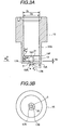
- FIG. 4 is a partially magnified view showing the valve sheet part and the neighborhood of the fuel injection port shown in FIG. 3A
- FIG. 5 is a horizontal cross-section view of the swirl orifice provided inside the nozzle body viewed from the line X-X' in FIG. 2.
- the fuel injection valve 1 shown in FIG. 1 is an example of the fuel injection valve using a magnet coil used as an actuator.
- a magnet coil used as an actuator.
- a fixed core 2, yoke (case) 3 and a movable core (plunger) 4 are provided.
- the fixed core 2 is an elongated hollow cylinder and has a flange 2A in its axis direction, and the lower half below the flange 2A is inserted in the yoke 3.
- the flange 2A is engaged in the open port at the upper part of the yoke 3, and by pressuring the marginal part of the open port at the upper part of the yoke 3 and establishing a plastic flow as shown by the symbol 50, the fixed core 2 an the yoke 3 are bonded plastically. This bondage may be realized by applying fastening forces.
- a terminal 8 of the magnetic coil 10 is provided at the flange 2A.
- a fuel channel 5 is formed so as to penetrate through the fixed core 2 in the axial direction, and a return spring 6 of the movable core 4 is inserted at one end of the fuel channel 5 (the end part opposite to the fuel flow-in part), and the movable core 4 is energized by the return spring in the valve-close direction (toward the valve sheet 7).
- a hollow spring adjuster 8 is provided for adjusting the spring force of the return spring 6, and the inside of the adjuster 8 forms a part of the fuel channel 5.
- the magnetic coil 10 is covered by molded resin, and a part of the fixed core 2 is inserted and fixed inside the bobbin 10A of the magnetic coil, and the magnetic coil 10 is provided inside the cylindrical yoke 3 as well as a part of the fixed core 2.
- the molded resin 11 protects the magnetic coil 10 and prevents the leak current.
- a component 18 is a seal ring for preventing the fuel from flowing into the coil assembly.
- the terminal 9 is buried inside the molded resin body placed above the yoke 4, and its one end is located at the connector part 20A and thus, forms the connector terminal.
- a hollow cylindrical nozzle with a bottom (nozzle body) 15 is fixed at the bottom part of the yoke 3.
- An orifice 17 used as the valve sheet 7 and the fuel injection port is provided at the bottom part of the nozzle 15, and a fuel swirling element (hereinafter referred also to a swirler) supported by the internal bottom of the nozzle is placed in the nozzle 15.
- the swirler 16 is located at the upper stream of the valve sheet 7.
- a guide hole (center hole) for the ball valve (valve body) is placed at the center of the swirler 16, and fuel channels 16B and 16B' for communicating between the fuel channel 14 inside the nozzle 15 and the guide hole 16A are formed at the peripheral and bottom parts of the swirler 16.
- FIG. 5 shows a projected view of the swirler 16 viewed at its bottom part and viewed from the line X-X', and the swirler 16 is composed of four circular arcs 16C segmented individually by 90 around its periphery and gaps between the adjacent circular arcs (fuel channels), and the circular arc 16C contact the inside surface of the nozzle and the open side of the gap 16B is covered by the internal surface of the nozzle 15 and thus forms the fuel channel, and by means of configuring the direction of channels so as to be eccentric with respect to the center of the swirler, the swirling force is applied to the fuel while the fuel flows through the fuel channels 16B and 16B'.
- a swirling force is applied to the fuel flowing out from the fuel channel 16B' and passing through the surrounding area of the valve body 13 at the upper stream of the valve sheet 7.
- the movable core 4 is connected to the hollow plunger rod 4A with a ball valve 13 fixed at its head.
- a fuel passage hole 41 is placed on the side wall of the plunger rod 4A.
- a component 21 is a stopper for limiting the stroke of the movable core 4 in its open direction.
- the fixed core, the yoke 3 and the movable core 4 are composed of magnetic materials, and the rod part 4A, the ball valve 13, the stopper 21 and the spring adjuster 8 are composed of non-magnetic materials.
- the ball valve 13 When the magnetic coil is not at current-carrying state, the ball valve 13 receives the spring force applied by the return spring 6 and the fuel pressure and contacts the sheet valve, and then, keep the valve opening state.
- the fuel flows through the piping apparatus such as fuel pump, fuel pressure regulator and accumulator, and then passes through the fuel channel 5, the filter 22 and the inside of the movable core 4, each placed in the fixed core 2 and through the internal channel, the fuel passage hole 41, the passage 14 in the nozzle (nozzle body) 15, and is injected directed into the inside of the cylinder of the engine thorough the orifice 17 while provided with the swirling force by the swirler and swirling at the tapered hole having the valve sheet 7.
- the piping apparatus such as fuel pump, fuel pressure regulator and accumulator
- FIGS. 2 to 4 the structure of the nozzle is described.
- the orifice used as the injection port 17 of the fuel and the diameter-extended hole 31 with its diameter extended at the entrance 17A of he injection port 17 toward the upper stream which accepts a part of the ball valve 13 and has the valve sheet 7 are formed at the central part of the bottom wall 15A of the nozzle 15 having a bottom and shaped in a hollow cylinder.
- the diameter-extended hole 31 is structured as a reverse cone in this example, it is allowed to make its shape partially a curved surface.
- the orifice forming the injection port 17 is slanted with respect to the longitudinal axis C of the fuel injection valve body, and its tilted angle (deflection angle) ⁇ is so determined as to be between 5° and 10° with respect to the longitudinal axis C of the fuel injection valve body.
- the fuel spray 47 injected out from the fuel injection valve 1 (in other word, the center line of the fuel spray) is deflected in a uniform direction (the direction in which the injection port 17 is deflected in terms of the view of the injection port 17 from the valve sheet 7) with respect to the longitudinal axis C of the fuel injection valve body.
- the marginal part of the outlet of the injection port 17 of the nozzle 15 is formed by a small raised part 30 to be described later in this embodiment, and the marginal part of the outlet 30 and the outlet 17B of the injection port provide a slant and non-perpendicular face with respect to the longitudinal axis C of the fuel injection valve body.
- the slant face 30'' extended out from the face of the outlet 15B of the injection port toward the injection direction is defined as a slant face upstream side
- the slant face 30' extended back from the face of the outlet 15B of the injection port toward the opposite direction to the injection direction is defined as a slant face downstream side.
- the length of the injection port 17 becomes at least axial asymmetry.
- the angle defined between the slant face of the outlet 17B of the injection port and the center line E of the injection port is made to be 90° in this embodiment, the shape of the outlet 17B of the injection port is a complete round, and the edge angle of the outlet 17B is axis symmetry.
- the length of the injection port 17 is axial asymmetry, and consequently, as for the orifice length 1 of the injection port 17, the orifice wall face length 12 for the slant face upper stream side 30'' of the marginal part of the outlet 30 and the orifice wall length 11 for he slant face down stream side 30' have such a relation as 12 > 11, and as for he channel length M from the contact position of the valve body 31 of the valve sheet 7 and the outlet 17B of the injection port, the length M2 for the slant face upper stream side 30'' of the marginal part of the outlet 30 and the length M1 for the slant face down stream side 30' of the marginal part of the outlet 30 have such a relation that M2 > M1, and thus, as the channel length of the swirling flow changes for the individual positions, a difference in the influence by the channel
- the loss for the side having the longer channel length M (M2) is larger and the reachable distance (the reachable distance L2 of the spray) of the spray at the M2 side (spray penetration and flow velocity) is also small, and in contrast, the loss for the side having the shorter channel length M (M1) is smaller and the reachable distance of the spray at the M side (the reachable distance L1 of the spray) is longer.
- the flow rate distribution of the fuel spray can be made to have directional dependency (that is, it is enabled to define such the flow rate distribution that the fuel spray quantity at the M1 side is larger than the fuel spray quantity at the M2 side).
- the fuel spray 47 injected from the injection port 17 of the nozzle 15 may be deflected in a definite direction with respect to the longitudinal axis C of the fuel injection valve body, and the spray shape is so defined that the reachable distance L1 of the spray at the deflected side may be larger and the reachable distance L2 of the fuel spray at another side opposite to the deflected side may be shorter (corresponding to Claim 1).
- a small raised part 30 with its height shorter than the length of the orifice 1 of the injection port 17 is formed at the center of the external face of the bottom part of the nozzle 15 having the injection port 17, and the injection port 17 has a inclination with respect to the longitudinal axis of the fuel injection valve body and its outlet 17B is formed at the small raised part 30.
- the small raised part 30 defines a wall part of the marginal part of the outlet of the injection port 17.
- the top face of the small raised part (the marginal part of the outlet) 30 provides such a slant face as the deflected direction side of its injection port is made lower and its non-deflected direction side is made higher in view of the outlet 17B of the injection port from the valve sheet 7 (corresponding to Claim 7).
- the ball valve 13, the diameter (the diameter of the part to which the valve body contacts) of the valve sheet, the angle of the valve sheet, the orifice (injection port) 17 and the small raised part 30 have the following specifications.
- the diameter of the pipe of the ball valve is 2mm
- the diameter of the valve sheet (the diameter of the sheet to which the valve body contacts) is 1.4mm
- the angle of the valve sheet is 90°
- the diameter of the orifice is from 0.6mm to 0.9mm
- the length of the orifice (the length along the center axis of the orifice) is 0.3 to 1.3 times of the diameter of the orifice
- the diameter of the small raised part is from 2 to 3 mm
- the height H2 of the slant upward wall part at the marginal part of the outlet of the orifice is from 0.43 to 0.8mm
- the height H1 of the slant downward wall part is from 0.1 to 0.46mm.
- the gradient of the slant ⁇ is from 5° to 10° (8.5° in
- the small raised part 30 in this embodiment is composed of an outline enclosed by a circular arc with its face perpendicular to the center line of the small raised part larger than a semi-circumference and a chord connected between its both ends.
- the height of the small raised part 30 at the chord side is made to be higher and the height of the small raised part 30 at the opposite side to the chord side, and thus, the top face of the small raised part is made to be a slant face.
- the injection port 17 is so weathered that the side of the inlet 17A of the injection port may be deflected toward the chord side with respect to the center line O of the small raised part, and that the side of the outlet 17B of the injection port is deflected toward the opposite side of the chord (corresponding to Claim 8).
- the outline of the small raised part 30 is composed of the arc and the chord, and that the gradient of the injection port 17 and the direction of the slant face of the top face of the small raised part are made to be matched with the arc and the chord, it is enabled that the deflection direction of the fuel spray of the fuel injection valve can be recognized by referring to the arc and the chord.
- the injection port 17 (the center line E of the injection port) is formed so as to have an inclination with respect to the longitudinal axis C of the fuel injection valve body, the intersecting point G of the longitudinal axis C of the fuel injection valve body and the center line E is located inside the orifice forming the injection port 17 (corresponding to Claim 9).
- the edge angle of the inlet 17A of the fuel injection port 17 becomes axial asymmetry with respect to the center line of the valve sheet 7 diameter (the center line of the valve sheet diameters matches to the canter line of the longitudinal axis C of the fuel injection valve body). It is assumed that the axial asymmetry of the inlet 17A of the injection port influences the fuel spray state.
- valve body 13 contacting the valve sheet 7 when the valve opens is shaped in a sphere, and that the top of the sphere of the valve body 13 is located below the inlet 17A of the injection port and gets into the inside of the injection port 17 when the valve is closed (corresponding to Claim 16). It is allowed that the top of the valve may be located at the same level of the inlet 17A of the injection port when the valve is closed.
- the dead volume (free space) between the top face of the valve body 13 and the inlet 17A of the injection port when the valve opens can be reduced and that the fuel can be sprayed with attenuation of the swirling force of the swirling fuel kept as little as possible.
- the fuel spray can be formed to be shaped in a cone which provides a high-density outside area having larger swirling energy and a coarse density inside area having lower swirling energy, and then, it is appreciated that the swirling energy can be used effectively and the grain refinement of the fuel spray can be achieved with such a shape as described above.
- the dead volume wall on which the residual fuel tends to attach is reduced as much as possible when the valve is closed, it is aimed to make the residual fuel kept from staying, and consequently increase the accuracy of the fuel air ratio.
- the condition to be required is y 2z (corresponding to Claim 15).
- the length of the injection port 17 is defined as 1 (the length 1 is the length of the orifice on the central axis of the injection port) and the diameter of the injection port is defined as d
- those parameters are determined so as to satisfy the relational expression 0.3 ⁇ l/d ⁇ 1.3 (corresponding to Claim 14).
- the reason why the lower bound of l/d is determined to be 0.3 is that the desired deflected angle for the fuel spray can not be obtained for the value lower than this lower bound, and the pressure loss and the grain size of the spray glow larger for the value larger than 1.3 and the required grain size (100 ⁇ m) can not be attained.
- the swirling direction of the fuel in this embodiment is counter clockwise viewed from the down stream side of the valve sheet, but clockwise viewed from the upper stream side of the valve sheet.
- a more preferable deflected spray can be obtained by making the swirling fuel oriented rather than using the swirling direction opposite to this orientation, in case that slant faces are provided at the outlet 17B and the top face of the marginal part 30 of the injection port 17, and that the injection port 17 is provided with a gradient so that the inlet 17A of the injection port 17 may be deflected toward the slant face upper stream side 30'' of the marginal part of the outlet with respect to the central axis C of the valve sheet and that the outlet 17B may be deflected toward the slant face down stream side 30' of the marginal part of the outlet.
- the nozzle 15 shaped in a hollow cylinder having a bottom includes a chip used as a swirler 16 as shown in FIG. 2, and the chip 16 has a guide hole 16A for the ball valve (valve body) 13 at its center, and eccentric fuel channels 16B and 16B' at its outer face and bottom face.
- the chip 16 has a guide hole 16A for the ball valve (valve body) 13 at its center, and eccentric fuel channels 16B and 16B' at its outer face and bottom face.
- the diameter of the inner surface of the nozzle is enlarged at the region from the corner 15C intersecting the inner bottom face 15B of the nozzle to the inside perimeter position 25D intersecting the vertical face Q of the chip axis at the middle point in the height of the chip 16, and a hollow 60 is formed at the corner 15C intersecting the inner bottom face of the nozzle 15 positioned below the face 15B accepting the chip of the nozzle inner bottom in the region of the inner enlarged perimeter 15F (corresponding to Claim 17).
- the position on the inner surface of the nozzle in which the chip 16 is provided is composed of inner surfaces having different inner diameters, and the inner surface 15G with smaller inner diameter is located upstream of the inner surface 15F with larger inner diameter and contacts the non-fuel channel face (circular arc face 16C shown in FIG. 5) on the outer face of the chip 16,
- the inner surface 15F with larger inner diameter is formed at the region from the corer 15C intersecting with the inner bottom face of the nozzle to the inner surface position 15D intersecting with the vertical face Q of the chip axis at the mid-point of the height of the chip.
- the hollow 60 in which the corner 15C is located is formed by the intersection between the taper 61 formed at the marginal part of the inner bottom face and the inner surface 15F with larger inner diameter.
- the boundary part 15D between the inner surfaces 15G and 15F with their own distinctive inner diameters is formed by a taper. In this embodiment, as an example, as shown in FIG.
- the inner diameter DS of the nozzle inner surface 15G with smaller inner diameter is determined to be ⁇ 5.9 mm
- the inner diameter DL of the nozzle inner surface 15F with larger inner diameter is determined to be ⁇ 6.2 mm
- the taper angle T ⁇ 1 of the inner diameter difference boundary position 15D is determined to be 30 with respect to the nozzle inner surface
- the taper angle T ⁇ 2 forming a hollow 60 is determined to be 60 with respect to the nozzle inner surface
- the depth HD is determined to be 0.26mm with respect to the nozzle inner surface
- the width W of the channel of the enlarged inner surface 15F is determined to be 3mm.
- the width of the channel of the fuel channel 16B' of the swirler 16 is 0.4m and the height of the channel is 0.19mm.
- an inner surface part (inner surface channel) 15F By forming an inner surface part (inner surface channel) 15F with its diameter enlarged and by defining a corner 15C at the hollow 16, the following operation and effect can be obtained.
- the fuel channel of the swirler is shaped in a simple elbow, and an intensive fuel pealing occurs at the corner of this channel structure, which causes an increase in the pressure loss in the fuel channel.
- the enlarged inner surface 15F contributes to an extension of the fuel channel near the corner C and a reduction of the flow velocity, and then, a reduction of the pressure loss due to the fuel pealing. It should be noted that, as the fuel channel is narrowed down after the fuel passes through the corner 14C, the flow velocity increases again.
- the tapers 15D and 61 are formed at the inlet and outlet of the enlarged inner surface 15F of the nozzle, the occurrence of the spreading loss and convergent loss in the fuel channel is suppressed as much as possible.
- the outer surface of the bottom part of the nozzle is polished and formed as non-perpendicular surface with respect to the longitudinal axis C of the fuel injection valve body, it is considered that the smoke and fuel is kept from attached on the inner surface.
- FIGS. 6 and 7 are explanatory drawings showing an example of applying the fuel injection valve in the present invention to the combustion system of the in-cylinder injection type gasoline engine, as shown in a partial cross-section view of the cylinder.
- the component 40 is a cylinder
- the component 41 is an ignition plug
- the component 42 is a piston
- the component 43 is an intake gas channel
- the component 44 is an exhaust gas channel
- the component 45 is an intake valve
- the component 46 is an exhaust valve.
- the ignition plug 41 is so mounted on the center of the top part (cylinder head) of the cylinder 40 so as to be aligned to the longitudinal axis A of the cylinder, and the intake valve 45 and the exhaust valve 46 are placed on one and the other side individually over the longitudinal axis A.
- the fuel injection valve 1 is mounted at the top part of the cylinder and around the marginal part of the cylinder near the intake valve 45 with a designated angle defined to be slanted to the face B perpendicular to the longitudinal axis A of the cylinder.
- the fuel injection valve 1 is mounted with such an angle as the longitudinal axis C of the fuel injection valve body intersects diagonally the longitudinal axis A of the cylinder.
- the deflected side (for example, the side wall 30a of the injection port 17 located on the right side of the drawing sheet of FIG. 2) is made to face to the ignition plug 41 (upwards), and the non-deflected side (for example, the side wall 30b of the injection port 17 located on the left side of the drawing sheet of FIG. 2) is made to face to the opposite side of the injection plug (downwards).
- the fuel injection valve is so defined that the injection port 17 facing to the inside of the cylinder 40 has a deflection angle ⁇ toward the ignition plug side with respect to the longitudinal axis C of the fuel injection valve body by using the above described injection port slant angle a (corresponding to Claims 3 and 4).
- the injection port 17 With a deflection angle ⁇ , the fuel spray 47 injected out from the fuel injection valve 1 (in other words, the center line D of the fuel spray) is deflected toward the ignition plug 41 with respect to the longitudinal axis C of the fuel injection valve body.
- the individual deflection angle of the center line D of the fuel spray and the longitudinal axis E of the injection port is almost identical to each other, and is between 5° and 10°.
- the reason why the deflection angle ⁇ of the injection port 17 with respect to the longitudinal axis C of the fuel injection valve body is determined to be between 5° and 10° is that the angle ⁇ 1 for the required spray direction (the angle ⁇ 3 for the deflected spray) as shown in FIG. 7 can not obtained for the angle lower than 5° due to the restriction on the engine mount angle of the fuel injection valve 1 , and that it is difficult to establish the required reachable distance of the fuel spray because the fuel channel loss (pressure loss) in the projection valve becomes larger for the angle larger than 10°.
- the injected fuel spray 47 can be deflected by the angle ⁇ 3 toward the ignition plug 41 with respect to the longitudinal axis C of the fuel injection valve body as shown in FIG. 7.
- the angle ⁇ 3 is an angle defined between the longitudinal axis C of the fuel injection valve body and the center line D of the fuel spray 47.
- the parameter ⁇ 1 in FIG. 7 is an angle for the required target spray direction and defined as an angle between the face B perpendicular the longitudinal axis A of the cylinder and the center line D of the fuel spray.
- the required spray direction ⁇ 1 is determined by the shape and size of the engine and is not necessarily a uniform value.
- the parameter ⁇ 2 is a mount angle of the fuel injection valve 1 on the engine, and defined as an angle between the reference surface B described above and the longitudinal axis C of the fuel injection valve body.
- the fuel spray 47 is shaped in a cone , and what can be obtained is such a spray shape as the fuel spray 47 is not axial symmetry with respect to the center line D of the spray, the reachable distance L1 (spray penetration) of the spray deflected toward the ignition plug 41 is larger and the reachable distance L2 of the spray at the side (the cavity 42a side of the piston 42) opposite to the deflection side is smaller.
- the fuel spray segment 47' of the fuel spray 47 injected at the ignition plug side is directed directly to the ignition plug 41, and then, an intensive mixed-air formation around the ignition plug 41 is promoted and an ignition performance of the mixed air can be established while an excellent gas mileage is attained.
- the spread of the fuel spray tends to be small.
- the fuel spray area and the spray angle ⁇ can be extended by the degree for the deflected direction of the spray direction toward the ignition plug 41, and therefore, too much reduction of the spread of the fuel spray can be avoided and hence, a compact spray for concentrating moderately the fuel spray around the ignition plug.
- the spray angle ⁇ is an angle of the spread of the furl spray on the cross section (plane) when the cross section is defined so as to cut the fuel spray 47 along its center line D.
- the fuel spray is performed at the intake stroke when the pressure is low at the uniform combustion mode, it will be appreciated that the fuel spray area (fuel spray angle ⁇ ) can be more extended than ever by the deflection of the spray direction toward the ignition plug, and the uniformity of the fuel spread in the cylinder can be increased.
- the average A/F at the stratified combustion mode is an average of A/F for the mixed air layer a concentrated around the ignition plug and A/F for its surrounding air layer b , and in this embodiment, a good conditioned combustion can be realized under such a super lean A/F ratio in which A/F for the mixed air layer a is 15, and A/F for the air layer is 50, and thus, the average A/F is 40.
- the smoke exhaust can be reduced by 1/2 to 1/4 compared with that by the conventional apparatus while an increase in the output performance can be maintained.
- FIG. 10 Another embodiment of the nozzle 15 in the fuel injection valve is shown in FIG. 10.
- the plane of the outlet 17B of the injection port 17 of the nozzle 15 is slanted with respect to the vertical face R perpendicular to the center line E of the injection port (corresponding to Claim 10).
- the angle defined between the face of the outlet 17B of the injection port and the vertical face R is 1.5° (that is, the angle defined between the center line E of the injection port and the face of the outlet 17B of the injection port is, for example, 88.5°, and is determined so as to be 1.5° smaller than the center line E of the injection port and the vertical face R).
- the angle ⁇ defined between the longitudinal axis E of the injection port and the longitudinal axis C of the injection valve body is determined to be 8.5°
- the angle ⁇ defined between the face 17B of the outlet of the injection port ad the vertical face of the longitudinal axis C of the injection valve body is 10°.
- the height of the small raised part 30 at the upward slant side 30'' is, for example, 0.43mm, and the height at the downward slant side 30' is 0.1mm.
- the difference between the channel lengths M1 and M2 of the injection port 17 can be increased (M2 > M1) and the arbitrary elliptic shape of the outlet of the injection port 17 and the edge angle of the outlet can be axial asymmetry, and the difference between the reachable distances L1 and L2 of the fuel spray can be provided (L1 > L2) owing to those geometrical features.
- M2 > M1 the channel length of the swirling flow is not identical in the circumferential direction of the injection port, and then, the pressure difference occurs for the wall face difference, and thus, the spray velocity for the longer channel length M2 is slower and the spray velocity for the shorter channel length M1 is faster.
- This property is increased as the slant angle of the face 17B of the outlet of the injection port is made larger.
- the face of the outlet 17B of the injection port 17 of the nozzle 15 is slanted with respect to the vertical face R of the center line E of the injection port in the example shown in FIG. 11 similarly to the example shown in FIG. 10, the longitudinal axis E of the injection port 17 is not slanted with respect to the longitudinal axis of the fuel injection valve body C.
- the difference between the channel lengths M1 and M2 of the injection port 17 can be increased (M2 > M1) and the shape of the outlet of the injection port 17 can be changed, and the edge angle of the outlet can be axial asymmetry, and the difference between the reachable distances L1 and L2 of the fuel spray can be provided (L1 > L2) owing to those geometrical features.
- the angle of the desired spray direction can be provided only by the mount angle of the fuel injection valve 1.
- FIG. 12 in which the nozzle 15 has an orifice used as the injection port 17 similarly as shown in the above described individual embodiments, a reverse-cone shaped hole (fuel swirling space) 13 having a diameter increasing from the inlet 17A position of the injection port 17 toward the upstream and accepting a part of the valve body (ball valve) 13, and having the valve sheet 7, but the following points make distinguished geometrical characteristic.
- the injection port 17 has no slant with respect to the longitudinal axis C of the injection valve body, the top face (the plane of the outlet of the injection port) of the small raised part used as the marginal part of the injection port is also not a slant face but a vertical face with respect to the longitudinal axis C of the injection valve body and the center line EB of the injection port 17.
- the injection port 17 is offset with respect to the longitudinal axis C of the injection valve body (corresponding to Claim 11). With this offset, the injection port 17 is also offset to the center line of the reverse-cone shaped hole 31 and the longitudinal axis of the ball valve 13.
- the inlet 17A of the injection port 17 provides a decline face from the offset side (the right hand side facing to the paper sheet with respect to the longitudinal axis C of the injection valve body in FIG. 12) to the non-offset side (the left hand side facing to the paper sheet with respect to the longitudinal axis C of the injection valve body).
- the flow velocity is supposed to be uniform in the circumference direction.
- the swirling fuel passes through the axial asymmetric channel with respect to the longitudinal axis C of the fuel valve body.
- the distance from the longitudinal axis C of the swirling fuel to the fuel channel wall at the offset side is long and the distance from the longitudinal axis C of the swirling fuel to the fuel channel wall at the non-offset side is short for the channel Y2.
- the flow velocity at the outer side in the radial direction of the swirling fuel with respect to the longitudinal axis C of the swirling is faster, there occurs such a flow velocity distribution and flow velocity difference in the swirling fuel that the flow velocity along the fuel channel wall at the offset side is high and the flow velocity along the fuel channel wall at the non-offset side is low.
- the swirling fuel channel Y2 is made offset with respect to the center C of the swirling fuel, such a flow velocity distribution as the flow velocity difference occurs as described above.
- the swirling fuel spray cone-shaped spray
- the flow velocity (spray reachable distance) and flow rate can be made higher at the offset side rather than at the non-offset side.
- a desired spray shape, flow velocity and flow rate distribution can be obtained by setting the offset value in responsive to the swirling force of the swirling fuel and setting the adequate length and diameter of the injection port.
- FIG. 3A shows an example of applying the offset of the injection port shown in FIG. 12 to the injection port having a deflection angle.
- a valve sheet 7, an injection port 17 located at the down stream of the valve sheet and a fuel swirling space S (reverse-cone shaped hole 31) located between the injection port 17 and the valve sheet 7 are formed at the nozzle 15.
- the injection port 17 has a slant with respect to the longitudinal axis C of the fuel injection valve body, and the fuel swirling space S is defined so as to be axial symmetry with respect to the longitudinal axis C of the fuel injection valve body, and the center of the inlet 17A of the injection is offset with respect to the longitudinal axis C of the fuel injection valve body (corresponding to Claim 12).
- the deflection direction of the injection port 17 is positioned at the offset direction in viewing the outlet 17B of the injection port.
- the spray flow velocity (spray reachable distance) in the deflection direction and the flow rate can be made larger than those in the non-deflection direction.
- the injection port 17 is deflected as described above, it is allowed to change the shape of the inlet 17A of the injection port in responsive to the degree of deflection, and the spray distribution tends to be deflected, and a desired spray shape, flow velocity and flow rate distribution can be obtained by means that this tendency can be increased or decreased by making the inlet 17A of the injection port offset to the center C of the swirling.
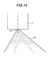
- FIG. 14 shows a modification example of the fuel injection valve having a deflected injection port described above in which the inner structure of the fuel injection valve 1 is not shown.
- the width of the outlet of the fuel channel 16B' of the swirler shown in FIG. 2 is made to be wider than the channel 16B' itself, and the space for holding the fuel is provided by this enlarged space.
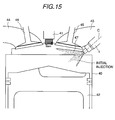
- the fuel staying in the fuel holder is also injected together at the initial phase of injecting the fuel spray, but as the fuel in the fuel holder does not have a swirling force, this fuel is formed as a spray form to be injected inside the swirling fuel to follow. This is used for the case of requiring such a spray form, a combustion system of the in-cylinder injection type gasoline engine using such a spray form is shown in FIG. 15.
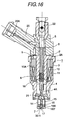
- FIG. 16 is a overall structure diagram showing another embodiment of the fuel injection valve of the present invention
- FIG. 17A is a vertical cross-section view showing the overall configuration of the nozzle used for the fuel injection valve
- FIG. 17B is a partial magnified cross-section view showing the surrounding area of the injection port.
- the fuel injection valve in this example is also aimed to define the similar deflected spray to that shown in FIG. 3A and the spray reachable distance so as to satisfy the relation L1 > L2.
- L1 the spray reachable distance
- a concave portion 31' shaped in a reverse-cone and having a curved surface on its top of the reverse-cone is formed on the inner surface by press work, and a valve sheet 7 is formed on the surface of the concave portion 31'.
- a semispherical small raised part 30 is formed by press work at the central part of the outer surface of the body top of the nozzle 15, and a fuel injection port 17 is formed at the thick part of the small raised part 30-1 so as to be slanted with respect to the longitudinal axis (nozzle axis) C of the fuel injection valve body (corresponding to Claim 13).
- the distance from the valve body contact position of the valve sheet to the outlet 17B of the injection port 17 (swirling fuel channel length) at the deflection side in viewing the injection port from the valve sheet can be shorter and the distance at the non-deflection side can be longer, and by making the edge angle of the inlet 17A and outlet 17B of the injection port 17 axial asymmetry, the reachable distance of the spray at the deflection side can be longer than that at the non-deflection side, and by adjusting arbitrarily the deflection angle of the injection port, a desired shape, flow velocity and spray distribution for the fuel spray can be obtained.
- optimal fuel spray forms individually optimum for the stratified combustion mode and the uniform combustion mode can be formed with a single fuel injection valve, and gasoline mileage and output power can be increased and a stable engine performance can be obtained in a wide range of engine rotation.
Landscapes
- Engineering & Computer Science (AREA)
- Chemical & Material Sciences (AREA)
- Combustion & Propulsion (AREA)
- Mechanical Engineering (AREA)
- General Engineering & Computer Science (AREA)
- Physics & Mathematics (AREA)
- Electromagnetism (AREA)
- Fuel-Injection Apparatus (AREA)
- Combustion Methods Of Internal-Combustion Engines (AREA)
Priority Applications (2)
| Application Number | Priority Date | Filing Date | Title |
|---|---|---|---|
| EP04012576A EP1469194B1 (fr) | 1997-11-26 | 1998-11-20 | Soupape d'injection de combustible |
| EP07019377A EP1867869A1 (fr) | 1997-11-26 | 1998-11-20 | Soupape d'injection de combustible |
Applications Claiming Priority (3)
| Application Number | Priority Date | Filing Date | Title |
|---|---|---|---|
| JP32445097 | 1997-11-26 | ||
| JP32445097A JP3771361B2 (ja) | 1997-11-26 | 1997-11-26 | 燃料噴射弁 |
| JP324450/97 | 1997-11-26 |
Related Child Applications (1)
| Application Number | Title | Priority Date | Filing Date |
|---|---|---|---|
| EP04012576A Division EP1469194B1 (fr) | 1997-11-26 | 1998-11-20 | Soupape d'injection de combustible |
Publications (3)
| Publication Number | Publication Date |
|---|---|
| EP0918155A2 true EP0918155A2 (fr) | 1999-05-26 |
| EP0918155A3 EP0918155A3 (fr) | 2002-08-21 |
| EP0918155B1 EP0918155B1 (fr) | 2004-10-13 |
Family
ID=18165956
Family Applications (3)
| Application Number | Title | Priority Date | Filing Date |
|---|---|---|---|
| EP04012576A Expired - Lifetime EP1469194B1 (fr) | 1997-11-26 | 1998-11-20 | Soupape d'injection de combustible |
| EP07019377A Withdrawn EP1867869A1 (fr) | 1997-11-26 | 1998-11-20 | Soupape d'injection de combustible |
| EP98121592A Expired - Lifetime EP0918155B1 (fr) | 1997-11-26 | 1998-11-20 | Soupape d'injection de combustible |
Family Applications Before (2)
| Application Number | Title | Priority Date | Filing Date |
|---|---|---|---|
| EP04012576A Expired - Lifetime EP1469194B1 (fr) | 1997-11-26 | 1998-11-20 | Soupape d'injection de combustible |
| EP07019377A Withdrawn EP1867869A1 (fr) | 1997-11-26 | 1998-11-20 | Soupape d'injection de combustible |
Country Status (6)
| Country | Link |
|---|---|
| US (1) | US6092743A (fr) |
| EP (3) | EP1469194B1 (fr) |
| JP (1) | JP3771361B2 (fr) |
| KR (1) | KR19990045584A (fr) |
| CN (11) | CN100376786C (fr) |
| DE (2) | DE69838520T2 (fr) |
Cited By (8)
| Publication number | Priority date | Publication date | Assignee | Title |
|---|---|---|---|---|
| WO2001029406A1 (fr) * | 1999-10-18 | 2001-04-26 | Orbital Engine Company (Australia) Pty Limited | Injection directe de carburants dans des moteurs a combustion interne |
| EP1124057A3 (fr) * | 2000-02-08 | 2002-11-20 | Siemens Automotive Corporation | Injecteur de combustible à jet conique incliné |
| EP1188920A3 (fr) * | 2000-09-18 | 2003-04-16 | Hitachi, Ltd. | Moteur à combustion interne |
| EP1316697A1 (fr) * | 2000-09-04 | 2003-06-04 | Hitachi, Ltd. | Moteur a allumage par etincelle du type a injection directe |
| EP1571330A1 (fr) * | 1999-03-17 | 2005-09-07 | Hitachi, Ltd. | Injecteur de combustible |
| WO2005108775A1 (fr) * | 2004-04-28 | 2005-11-17 | Siemens Vdo Automotive Corporation | Poinçon asymetrique |
| EP1734244A2 (fr) * | 1999-12-15 | 2006-12-20 | Hitachi, Ltd. | Appareil et méthode d'injection de combustible dans le cylindre d'un moteur à combustion interne |
| EP1762723A1 (fr) * | 2005-09-13 | 2007-03-14 | Hitachi, Ltd. | Soupape d'injection de carburant et procédé de production d'orifices de sortie |
Families Citing this family (39)
| Publication number | Priority date | Publication date | Assignee | Title |
|---|---|---|---|---|
| JP3932697B2 (ja) * | 1998-10-01 | 2007-06-20 | 株式会社日立製作所 | 筒内噴射型内燃機関の燃料噴射方法および、燃料噴射弁,内燃機関,燃焼方法 |
| US6935578B1 (en) * | 1998-11-25 | 2005-08-30 | Hitachi, Ltd. | Fuel injection valve |
| JP3810583B2 (ja) * | 1999-05-13 | 2006-08-16 | 三菱電機株式会社 | 燃料噴射弁 |
| EP1191199A1 (fr) * | 1999-06-11 | 2002-03-27 | Hitachi, Ltd. | Moteur a injection directe et procede de combustion destine audit moteur |
| DE19928204A1 (de) * | 1999-06-19 | 2000-12-21 | Bosch Gmbh Robert | Brennstoffeinspritzventil |
| JP3780472B2 (ja) | 2000-01-27 | 2006-05-31 | 愛三工業株式会社 | 燃料噴射弁 |
| US6422486B1 (en) | 2000-03-31 | 2002-07-23 | Siemens Automotive Corporation | Armature/needle assembly for a fuel injector and method of manufacturing same |
| DE10049034B4 (de) * | 2000-10-04 | 2005-08-04 | Robert Bosch Gmbh | Brennstoffeinspritzventil |
| EP1312795B1 (fr) | 2001-10-19 | 2007-07-11 | Hitachi, Ltd. | Injecteur à carburant |
| JP3931802B2 (ja) * | 2001-12-27 | 2007-06-20 | 株式会社日立製作所 | 燃料噴射弁とその装置及び内燃機関並びに燃料噴射弁の製造方法及びそのノズルボディとその製造方法 |
| JP2003269220A (ja) * | 2002-03-19 | 2003-09-25 | Hitachi Ltd | 低排気型筒内噴射エンジンの構成および制御装置 |
| US7357124B2 (en) * | 2002-05-10 | 2008-04-15 | Philip Morris Usa Inc. | Multiple capillary fuel injector for an internal combustion engine |
| DE10341365A1 (de) * | 2002-09-09 | 2004-05-06 | Hitachi, Ltd. | Kraftstoffeinspritzventil und damit ausgerüstete Brennkraftmaschine des Zylindereinspritzungstyps |
| JP3759918B2 (ja) * | 2002-10-16 | 2006-03-29 | 三菱電機株式会社 | 燃料噴射弁 |
| JP2004353661A (ja) | 2003-05-01 | 2004-12-16 | Hitachi Ltd | 燃料噴射弁及びそれを備えた筒内噴射式内燃機関 |
| DE60320235T2 (de) * | 2003-05-26 | 2009-05-28 | Continental Automotive Gmbh | Einspritzdüse mit verbesserter Einspritzung und Verfahren zu deren Herstellung |
| CN1661212B (zh) * | 2003-08-21 | 2011-08-17 | 周亮俊 | 高效内燃机及其燃烧方法 |
| JP4071694B2 (ja) * | 2003-09-12 | 2008-04-02 | 株式会社日立製作所 | 内燃機関の燃料噴射装置 |
| US7198207B2 (en) * | 2004-11-05 | 2007-04-03 | Visteon Global Technologies, Inc. | Low pressure fuel injector nozzle |
| US7438241B2 (en) * | 2004-11-05 | 2008-10-21 | Visteon Global Technologies, Inc. | Low pressure fuel injector nozzle |
| US7124963B2 (en) * | 2004-11-05 | 2006-10-24 | Visteon Global Technologies, Inc. | Low pressure fuel injector nozzle |
| US7104475B2 (en) * | 2004-11-05 | 2006-09-12 | Visteon Global Technologies, Inc. | Low pressure fuel injector nozzle |
| US7137577B2 (en) * | 2004-11-05 | 2006-11-21 | Visteon Global Technologies, Inc. | Low pressure fuel injector nozzle |
| US7185831B2 (en) * | 2004-11-05 | 2007-03-06 | Ford Motor Company | Low pressure fuel injector nozzle |
| US7168637B2 (en) * | 2004-11-05 | 2007-01-30 | Visteon Global Technologies, Inc. | Low pressure fuel injector nozzle |
| US7051957B1 (en) * | 2004-11-05 | 2006-05-30 | Visteon Global Technologies, Inc. | Low pressure fuel injector nozzle |
| JP2006200494A (ja) * | 2005-01-24 | 2006-08-03 | Toyota Motor Corp | 筒内噴射式火花点火内燃機関 |
| JP4649359B2 (ja) * | 2006-04-06 | 2011-03-09 | トヨタ自動車株式会社 | 冷却器 |
| DE102006043460A1 (de) * | 2006-09-15 | 2008-03-27 | Man Diesel Se | Verfahren zur Optimierung einer Einspritzdüse für eine Brennkraftmaschine |
| WO2009081615A1 (fr) * | 2007-12-25 | 2009-07-02 | Mitsubishi Electric Corporation | Soupape d'injection de carburant et procédé de formation de son orifice d'injection |
| ES2744845T3 (es) | 2011-10-10 | 2020-02-26 | Kmt Waterjet Systems Inc | Conexión de alta presión sin junta |
| DE102012209326A1 (de) * | 2012-06-01 | 2013-12-05 | Robert Bosch Gmbh | Brennstoffeinspritzventil |
| CN102705109B (zh) * | 2012-06-18 | 2015-09-16 | 中国南方航空工业(集团)有限公司 | 油量调节装置 |
| KR101337713B1 (ko) * | 2012-12-20 | 2013-12-06 | 주식회사 현대케피코 | 연료 미립화 밸브 시트 바디를 구비한 차량용 고압 직분식 인젝터 |
| JP2016169739A (ja) * | 2016-05-23 | 2016-09-23 | 株式会社デンソー | 燃料噴射装置 |
| DK179281B1 (en) * | 2016-12-13 | 2018-04-03 | Man Diesel & Turbo Filial Af Man Diesel & Turbo Se Tyskland | Nozzle for fuel valve for injecting fuel into the cylinders of a large turbocharged two-stroke compression-ignited internal combustion engine |
| DK179146B1 (en) * | 2016-12-13 | 2017-12-04 | Man Diesel & Turbo Filial Af Man Diesel & Turbo Se Tyskland | Nozzle for fuel valve for injecting fuel into the cylinders of a large turbocharged two-stroke compression-ignited internal combustion engineand and an engine therefore |
| US10927804B2 (en) | 2017-06-07 | 2021-02-23 | Ford Global Technologies, Llc | Direct fuel injector |
| CN112044613B (zh) * | 2020-10-19 | 2021-09-24 | 重庆渝江压铸有限公司 | 通机缸体自动喷油机 |
Citations (4)
| Publication number | Priority date | Publication date | Assignee | Title |
|---|---|---|---|---|
| JPH0533739A (ja) | 1991-07-25 | 1993-02-09 | Japan Electron Control Syst Co Ltd | アシストエア式フユーエルインジエクタ |
| JPH06221249A (ja) | 1993-01-29 | 1994-08-09 | Mazda Motor Corp | エンジンの燃料噴射装置 |
| JPH07119584A (ja) | 1993-10-15 | 1995-05-09 | Toyota Motor Corp | 燃料噴射弁におけるスワールノズル |
| JPH08296531A (ja) | 1995-04-28 | 1996-11-12 | Nippondenso Co Ltd | 燃料噴射弁 |
Family Cites Families (27)
| Publication number | Priority date | Publication date | Assignee | Title |
|---|---|---|---|---|
| FR1197303A (fr) * | 1957-07-05 | 1959-11-30 | Maschf Augsburg Nuernberg Ag | Injecteur, notamment pour moteurs à combustion interne |
| DE2746010C2 (de) * | 1977-10-13 | 1985-02-14 | M.A.N. Maschinenfabrik Augsburg-Nürnberg AG, 8500 Nürnberg | Kraftstoffeinspritzdüse für Brennkraftmaschinen |
| JPS5546576U (fr) * | 1978-09-22 | 1980-03-26 | ||
| DE2902417A1 (de) * | 1979-01-23 | 1980-07-31 | Maschf Augsburg Nuernberg Ag | Kraftstoff-einspritzduese fuer brennkraftmaschinen |
| DE3407545A1 (de) * | 1984-03-01 | 1985-09-05 | Hubert 8500 Nürnberg Keiczek | Kraftstoff-einspritzduese fuer brennkraftmaschinen |
| DE3502642A1 (de) * | 1985-01-26 | 1986-07-31 | Daimler-Benz Ag, 7000 Stuttgart | Kraftstoffeinspritzventil fuer eine luftverdichtende einspritzbrennkraftmaschine |
| JPS61221249A (ja) * | 1985-03-27 | 1986-10-01 | Toyoda Gosei Co Ltd | 液圧シリンダ用シ−ル部品 |
| US4958604A (en) * | 1988-02-10 | 1990-09-25 | Toyota Jidosha Kabushiki Kaisha | Direct fuel injection type spark ignition internal combustion engine |
| US5058549A (en) * | 1988-02-26 | 1991-10-22 | Toyota Jidosha Kabushiki Kaisha | Fuel swirl generation type fuel injection valve and direct fuel injection type spark ignition internal combustion engine |
| JPH025753A (ja) * | 1988-06-23 | 1990-01-10 | Aisan Ind Co Ltd | 燃料噴射弁とそのノズル |
| JP2628742B2 (ja) * | 1989-03-10 | 1997-07-09 | 株式会社日立製作所 | 電磁式燃料噴射弁 |
| US5054691A (en) * | 1989-11-03 | 1991-10-08 | Industrial Technology Research Institute | Fuel oil injector with a floating ball as its valve unit |
| JP2819702B2 (ja) * | 1989-12-12 | 1998-11-05 | 株式会社デンソー | 燃料噴射弁 |
| US5170945A (en) * | 1991-12-10 | 1992-12-15 | Siemens Automotive L.P. | Fuel injector that swirls and throttles the flow to create to a toroidal fuel cloud |
| JPH0763140A (ja) * | 1993-08-27 | 1995-03-07 | Toyota Motor Corp | 燃料噴射弁の噴射孔の形成方法 |
| JP3498334B2 (ja) * | 1993-11-08 | 2004-02-16 | 株式会社日立製作所 | 内燃機関の吸気装置 |
| DE19518950B4 (de) * | 1994-05-23 | 2007-03-29 | Nissan Motor Co., Ltd., Yokohama | Kraftstoffeinspritzdüse |
| JP3365147B2 (ja) * | 1994-05-23 | 2003-01-08 | 日産自動車株式会社 | 内燃機関の燃料噴射弁 |
| JPH08177498A (ja) * | 1994-12-20 | 1996-07-09 | Nissan Motor Co Ltd | 直噴型火花点火式内燃機関 |
| JPH08232813A (ja) * | 1995-02-27 | 1996-09-10 | Aisan Ind Co Ltd | インジェクタ |
| JP3380379B2 (ja) * | 1995-04-27 | 2003-02-24 | ヤマハ発動機株式会社 | 筒内噴射エンジン |
| JPH09126095A (ja) * | 1995-10-31 | 1997-05-13 | Toyota Central Res & Dev Lab Inc | 燃料噴射弁 |
| JP3478920B2 (ja) * | 1996-02-14 | 2003-12-15 | 株式会社日立製作所 | 筒内燃料噴射装置およびそれを搭載した内燃機関 |
| JPH09280135A (ja) * | 1996-04-17 | 1997-10-28 | Toyota Motor Corp | 燃料噴射弁における噴射孔形成部構造 |
| JP3625106B2 (ja) * | 1996-07-29 | 2005-03-02 | 三菱電機株式会社 | 燃料噴射弁 |
| JPH10176631A (ja) * | 1996-12-18 | 1998-06-30 | Nippon Soken Inc | 燃料噴射弁 |
| US5878962A (en) * | 1997-09-24 | 1999-03-09 | Siemens Automotive Corporation | Pressure swirl injector with angled cone spray for fuel injection |
-
1997
- 1997-11-26 JP JP32445097A patent/JP3771361B2/ja not_active Expired - Lifetime
-
1998
- 1998-11-20 DE DE69838520T patent/DE69838520T2/de not_active Expired - Fee Related
- 1998-11-20 EP EP04012576A patent/EP1469194B1/fr not_active Expired - Lifetime
- 1998-11-20 DE DE69826964T patent/DE69826964T2/de not_active Expired - Fee Related
- 1998-11-20 EP EP07019377A patent/EP1867869A1/fr not_active Withdrawn
- 1998-11-20 EP EP98121592A patent/EP0918155B1/fr not_active Expired - Lifetime
- 1998-11-25 US US09/199,456 patent/US6092743A/en not_active Expired - Lifetime
- 1998-11-25 KR KR1019980050786A patent/KR19990045584A/ko not_active Application Discontinuation
- 1998-11-26 CN CNB2006100088338A patent/CN100376786C/zh not_active Expired - Fee Related
- 1998-11-26 CN CNB981223729A patent/CN1138918C/zh not_active Expired - Fee Related
-
2001
- 2001-09-14 CN CNB011330856A patent/CN1258646C/zh not_active Expired - Fee Related
- 2001-09-14 CN CN01133084A patent/CN1356463A/zh active Pending
- 2001-09-14 CN CN01133082A patent/CN1356461A/zh active Pending
- 2001-09-14 CN CN01133081A patent/CN1356460A/zh active Pending
- 2001-09-14 CN CN01133075A patent/CN1356458A/zh active Pending
- 2001-09-14 CN CN01133086A patent/CN1356456A/zh active Pending
- 2001-09-14 CN CN01133076A patent/CN1356459A/zh active Pending
- 2001-09-14 CN CNB011330740A patent/CN1186527C/zh not_active Expired - Fee Related
- 2001-09-14 CN CN01133083A patent/CN1356462A/zh active Pending
Patent Citations (4)
| Publication number | Priority date | Publication date | Assignee | Title |
|---|---|---|---|---|
| JPH0533739A (ja) | 1991-07-25 | 1993-02-09 | Japan Electron Control Syst Co Ltd | アシストエア式フユーエルインジエクタ |
| JPH06221249A (ja) | 1993-01-29 | 1994-08-09 | Mazda Motor Corp | エンジンの燃料噴射装置 |
| JPH07119584A (ja) | 1993-10-15 | 1995-05-09 | Toyota Motor Corp | 燃料噴射弁におけるスワールノズル |
| JPH08296531A (ja) | 1995-04-28 | 1996-11-12 | Nippondenso Co Ltd | 燃料噴射弁 |
Cited By (14)
| Publication number | Priority date | Publication date | Assignee | Title |
|---|---|---|---|---|
| US7231902B2 (en) | 1999-03-17 | 2007-06-19 | Hitachi, Ltd. | Fuel injection valve and internal combustion engine mounting the same |
| EP1571330A1 (fr) * | 1999-03-17 | 2005-09-07 | Hitachi, Ltd. | Injecteur de combustible |
| US6755175B1 (en) | 1999-10-18 | 2004-06-29 | Orbital Engine Company (Australia) Pty Limited | Direct injection of fuels in internal combustion engines |
| WO2001029406A1 (fr) * | 1999-10-18 | 2001-04-26 | Orbital Engine Company (Australia) Pty Limited | Injection directe de carburants dans des moteurs a combustion interne |
| EP1734244A2 (fr) * | 1999-12-15 | 2006-12-20 | Hitachi, Ltd. | Appareil et méthode d'injection de combustible dans le cylindre d'un moteur à combustion interne |
| EP1734244A3 (fr) * | 1999-12-15 | 2007-08-29 | Hitachi, Ltd. | Appareil et méthode d'injection de combustible dans le cylindre d'un moteur à combustion interne |
| EP1124057A3 (fr) * | 2000-02-08 | 2002-11-20 | Siemens Automotive Corporation | Injecteur de combustible à jet conique incliné |
| EP1316697A4 (fr) * | 2000-09-04 | 2004-05-26 | Hitachi Ltd | Moteur a allumage par etincelle du type a injection directe |
| EP1316697A1 (fr) * | 2000-09-04 | 2003-06-04 | Hitachi, Ltd. | Moteur a allumage par etincelle du type a injection directe |
| US6668793B2 (en) | 2000-09-18 | 2003-12-30 | Hitachi, Ltd. | Internal combustion engine |
| EP1188920A3 (fr) * | 2000-09-18 | 2003-04-16 | Hitachi, Ltd. | Moteur à combustion interne |
| WO2005108775A1 (fr) * | 2004-04-28 | 2005-11-17 | Siemens Vdo Automotive Corporation | Poinçon asymetrique |
| EP1762723A1 (fr) * | 2005-09-13 | 2007-03-14 | Hitachi, Ltd. | Soupape d'injection de carburant et procédé de production d'orifices de sortie |
| US7874070B2 (en) | 2005-09-13 | 2011-01-25 | Hitachi, Ltd. | Injection valve and method of making orifice |
Also Published As
| Publication number | Publication date |
|---|---|
| DE69826964D1 (de) | 2004-11-18 |
| EP1469194B1 (fr) | 2007-10-03 |
| CN1356458A (zh) | 2002-07-03 |
| DE69826964T2 (de) | 2006-02-23 |
| CN1258646C (zh) | 2006-06-07 |
| CN1818371A (zh) | 2006-08-16 |
| CN1138918C (zh) | 2004-02-18 |
| KR19990045584A (ko) | 1999-06-25 |
| CN1356460A (zh) | 2002-07-03 |
| JP3771361B2 (ja) | 2006-04-26 |
| EP0918155B1 (fr) | 2004-10-13 |
| CN1356464A (zh) | 2002-07-03 |
| CN1218137A (zh) | 1999-06-02 |
| CN1356456A (zh) | 2002-07-03 |
| DE69838520T2 (de) | 2008-07-03 |
| CN1356461A (zh) | 2002-07-03 |
| CN1186527C (zh) | 2005-01-26 |
| JPH11159421A (ja) | 1999-06-15 |
| EP1469194A1 (fr) | 2004-10-20 |
| CN1356459A (zh) | 2002-07-03 |
| EP0918155A3 (fr) | 2002-08-21 |
| EP1867869A1 (fr) | 2007-12-19 |
| CN1356457A (zh) | 2002-07-03 |
| DE69838520D1 (de) | 2007-11-15 |
| US6092743A (en) | 2000-07-25 |
| CN100376786C (zh) | 2008-03-26 |
| CN1356463A (zh) | 2002-07-03 |
| CN1356462A (zh) | 2002-07-03 |
Similar Documents
| Publication | Publication Date | Title |
|---|---|---|
| EP0918155B1 (fr) | Soupape d'injection de combustible | |
| KR930004967B1 (ko) | 전자식 연료 분사밸브 | |
| KR100482712B1 (ko) | 직접 분사 연료 분사기 및 이 분사기를 장착한 내연 기관 | |
| US6439484B2 (en) | Fluid injection nozzle | |
| KR100601188B1 (ko) | 가압된 와류 연료 인젝터를 위한 플랫 니들 | |
| KR20000062925A (ko) | 연료 분사 밸브 및 이를 장착한 내연 기관 | |
| US6935578B1 (en) | Fuel injection valve | |
| JP2004514834A (ja) | 燃料噴射弁 | |
| JP4043966B2 (ja) | 燃料噴射弁 | |
| JP3419692B2 (ja) | 筒内噴射式内燃機関および筒内噴射用燃料噴射弁 | |
| JP2007224929A (ja) | 燃料噴射弁 | |
| JPH11336643A (ja) | 筒内噴射用電磁式燃料噴射弁 | |
| JP3445805B2 (ja) | 燃料噴射弁 | |
| JP2002130084A (ja) | 燃料噴射弁およびこれを搭載した内燃機関 | |
| JP2000303935A (ja) | 筒内燃料噴射装置 | |
| JP2001123910A (ja) | 筒内噴射用燃料噴射弁 | |
| JP2000314355A (ja) | 筒内燃料噴射装置 | |
| JP2000230469A (ja) | 筒内燃料噴射装置 | |
| JP2000230468A (ja) | 筒内燃料噴射装置 | |
| JP2000314354A (ja) | 筒内燃料噴射装置 |
Legal Events
| Date | Code | Title | Description |
|---|---|---|---|
| PUAI | Public reference made under article 153(3) epc to a published international application that has entered the european phase |
Free format text: ORIGINAL CODE: 0009012 |
|
| AK | Designated contracting states |
Kind code of ref document: A2 Designated state(s): AT BE CH CY DE DK ES FI FR GB GR IE IT LI LU MC NL PT SE |
|
| AX | Request for extension of the european patent |
Free format text: AL;LT;LV;MK;RO;SI |
|
| PUAL | Search report despatched |
Free format text: ORIGINAL CODE: 0009013 |
|
| AK | Designated contracting states |
Kind code of ref document: A3 Designated state(s): AT BE CH CY DE DK ES FI FR GB GR IE IT LI LU MC NL PT SE |
|
| AX | Request for extension of the european patent |
Free format text: AL;LT;LV;MK;RO;SI |
|
| 17P | Request for examination filed |
Effective date: 20021213 |
|
| 17Q | First examination report despatched |
Effective date: 20030123 |
|
| AKX | Designation fees paid |
Designated state(s): DE FR GB IT |
|
| GRAP | Despatch of communication of intention to grant a patent |
Free format text: ORIGINAL CODE: EPIDOSNIGR1 |
|
| RIN1 | Information on inventor provided before grant (corrected) |
Inventor name: ISHIKAWA, TOHRU Inventor name: SASAKI, YUICHI Inventor name: SEKINE, ATSUSHI Inventor name: NAMAIZAWA, YASUO Inventor name: SHIBATA, KOJI |
|
| GRAS | Grant fee paid |
Free format text: ORIGINAL CODE: EPIDOSNIGR3 |
|
| GRAA | (expected) grant |
Free format text: ORIGINAL CODE: 0009210 |
|
| AK | Designated contracting states |
Kind code of ref document: B1 Designated state(s): DE FR GB IT |
|
| REG | Reference to a national code |
Ref country code: GB Ref legal event code: FG4D |
|
| REF | Corresponds to: |
Ref document number: 69826964 Country of ref document: DE Date of ref document: 20041118 Kind code of ref document: P |
|
| ET | Fr: translation filed | ||
| PLBE | No opposition filed within time limit |
Free format text: ORIGINAL CODE: 0009261 |
|
| STAA | Information on the status of an ep patent application or granted ep patent |
Free format text: STATUS: NO OPPOSITION FILED WITHIN TIME LIMIT |
|
| 26N | No opposition filed |
Effective date: 20050714 |
|
| PGFP | Annual fee paid to national office [announced via postgrant information from national office to epo] |
Ref country code: DE Payment date: 20081126 Year of fee payment: 11 |
|
| PGFP | Annual fee paid to national office [announced via postgrant information from national office to epo] |
Ref country code: FR Payment date: 20081017 Year of fee payment: 11 |
|
| PGFP | Annual fee paid to national office [announced via postgrant information from national office to epo] |
Ref country code: GB Payment date: 20081021 Year of fee payment: 11 |
|
| GBPC | Gb: european patent ceased through non-payment of renewal fee |
Effective date: 20091120 |
|
| REG | Reference to a national code |
Ref country code: FR Ref legal event code: ST Effective date: 20100730 |
|
| PG25 | Lapsed in a contracting state [announced via postgrant information from national office to epo] |
Ref country code: FR Free format text: LAPSE BECAUSE OF NON-PAYMENT OF DUE FEES Effective date: 20091130 |
|
| PG25 | Lapsed in a contracting state [announced via postgrant information from national office to epo] |
Ref country code: DE Free format text: LAPSE BECAUSE OF NON-PAYMENT OF DUE FEES Effective date: 20100601 |
|
| PG25 | Lapsed in a contracting state [announced via postgrant information from national office to epo] |
Ref country code: GB Free format text: LAPSE BECAUSE OF NON-PAYMENT OF DUE FEES Effective date: 20091120 |
|
| PGFP | Annual fee paid to national office [announced via postgrant information from national office to epo] |
Ref country code: IT Payment date: 20141106 Year of fee payment: 17 |
|
| PG25 | Lapsed in a contracting state [announced via postgrant information from national office to epo] |
Ref country code: IT Free format text: LAPSE BECAUSE OF NON-PAYMENT OF DUE FEES Effective date: 20151120 |