EP0916520A2 - Fahrradrad - Google Patents
Fahrradrad Download PDFInfo
- Publication number
- EP0916520A2 EP0916520A2 EP98308966A EP98308966A EP0916520A2 EP 0916520 A2 EP0916520 A2 EP 0916520A2 EP 98308966 A EP98308966 A EP 98308966A EP 98308966 A EP98308966 A EP 98308966A EP 0916520 A2 EP0916520 A2 EP 0916520A2
- Authority
- EP
- European Patent Office
- Prior art keywords
- rim
- spoke
- spokes
- section
- openings
- Prior art date
- Legal status (The legal status is an assumption and is not a legal conclusion. Google has not performed a legal analysis and makes no representation as to the accuracy of the status listed.)
- Granted
Links
Images


Classifications
-
- B—PERFORMING OPERATIONS; TRANSPORTING
- B60—VEHICLES IN GENERAL
- B60B—VEHICLE WHEELS; CASTORS; AXLES FOR WHEELS OR CASTORS; INCREASING WHEEL ADHESION
- B60B21/00—Rims
- B60B21/06—Rims characterised by means for attaching spokes, i.e. spoke seats
- B60B21/062—Rims characterised by means for attaching spokes, i.e. spoke seats for bicycles
-
- B—PERFORMING OPERATIONS; TRANSPORTING
- B60—VEHICLES IN GENERAL
- B60B—VEHICLE WHEELS; CASTORS; AXLES FOR WHEELS OR CASTORS; INCREASING WHEEL ADHESION
- B60B1/00—Spoked wheels; Spokes thereof
- B60B1/02—Wheels with wire or other tension spokes
- B60B1/0215—Wheels with wire or other tension spokes characterised by specific grouping of spokes
- B60B1/0223—Wheels with wire or other tension spokes characterised by specific grouping of spokes the dominant aspect being the spoke arrangement pattern
-
- B—PERFORMING OPERATIONS; TRANSPORTING
- B60—VEHICLES IN GENERAL
- B60B—VEHICLE WHEELS; CASTORS; AXLES FOR WHEELS OR CASTORS; INCREASING WHEEL ADHESION
- B60B1/00—Spoked wheels; Spokes thereof
- B60B1/02—Wheels with wire or other tension spokes
- B60B1/0261—Wheels with wire or other tension spokes characterised by spoke form
- B60B1/0269—Wheels with wire or other tension spokes characterised by spoke form the spoke being curved or deformed over substantial part of length
-
- B—PERFORMING OPERATIONS; TRANSPORTING
- B60—VEHICLES IN GENERAL
- B60B—VEHICLE WHEELS; CASTORS; AXLES FOR WHEELS OR CASTORS; INCREASING WHEEL ADHESION
- B60B1/00—Spoked wheels; Spokes thereof
- B60B1/02—Wheels with wire or other tension spokes
- B60B1/0261—Wheels with wire or other tension spokes characterised by spoke form
- B60B1/0276—Wheels with wire or other tension spokes characterised by spoke form the spoke being crooked in the middle and having double length
-
- B—PERFORMING OPERATIONS; TRANSPORTING
- B60—VEHICLES IN GENERAL
- B60B—VEHICLE WHEELS; CASTORS; AXLES FOR WHEELS OR CASTORS; INCREASING WHEEL ADHESION
- B60B1/00—Spoked wheels; Spokes thereof
- B60B1/02—Wheels with wire or other tension spokes
- B60B1/04—Attaching spokes to rim or hub
- B60B1/041—Attaching spokes to rim or hub of bicycle wheels
-
- B—PERFORMING OPERATIONS; TRANSPORTING
- B60—VEHICLES IN GENERAL
- B60B—VEHICLE WHEELS; CASTORS; AXLES FOR WHEELS OR CASTORS; INCREASING WHEEL ADHESION
- B60B1/00—Spoked wheels; Spokes thereof
- B60B1/02—Wheels with wire or other tension spokes
- B60B1/04—Attaching spokes to rim or hub
- B60B1/042—Attaching spokes to hub
-
- B—PERFORMING OPERATIONS; TRANSPORTING
- B60—VEHICLES IN GENERAL
- B60B—VEHICLE WHEELS; CASTORS; AXLES FOR WHEELS OR CASTORS; INCREASING WHEEL ADHESION
- B60B21/00—Rims
- B60B21/02—Rims characterised by transverse section
- B60B21/025—Rims characterised by transverse section the transverse section being hollow
-
- B—PERFORMING OPERATIONS; TRANSPORTING
- B60—VEHICLES IN GENERAL
- B60B—VEHICLE WHEELS; CASTORS; AXLES FOR WHEELS OR CASTORS; INCREASING WHEEL ADHESION
- B60B21/00—Rims
- B60B21/06—Rims characterised by means for attaching spokes, i.e. spoke seats
- B60B21/064—Rims characterised by means for attaching spokes, i.e. spoke seats characterised by shape of spoke mounting holes, e.g. elliptical or triangular
-
- B—PERFORMING OPERATIONS; TRANSPORTING
- B60—VEHICLES IN GENERAL
- B60B—VEHICLE WHEELS; CASTORS; AXLES FOR WHEELS OR CASTORS; INCREASING WHEEL ADHESION
- B60B21/00—Rims
- B60B21/06—Rims characterised by means for attaching spokes, i.e. spoke seats
- B60B21/066—Rims characterised by means for attaching spokes, i.e. spoke seats the spoke mounting means being located on a flange oriented radially and formed on the radially inner side of the rim well
-
- B—PERFORMING OPERATIONS; TRANSPORTING
- B60—VEHICLES IN GENERAL
- B60B—VEHICLE WHEELS; CASTORS; AXLES FOR WHEELS OR CASTORS; INCREASING WHEEL ADHESION
- B60B21/00—Rims
- B60B21/08—Rims characterised by having braking surfaces
Definitions
- This invention generally relates to a bicycle wheel with a hub adapted to be mounted to a bicycle frame, an annular rim and a plurality of spokes extending inwardly from the rim to the hub. More specifically, the present invention relates to the connection between the spokes and the rim of the bicycle wheel.
- Bicycling is becoming an increasingly more popular form of recreation as well as a means of transportation. Moreover, bicycling has also become a very popular competitive sport for both amateurs and professionals. Whether the bicycle is used for recreation, transportation or competition, the bicycle industry is constantly improving the various coniponents of the bicycle.
- One particular component of bicycles which has been extensively redesigned over the past years is the bicycle wheel. Bicycle wheels are constantly being redesigned to be lightweight and more aerodynamic in design as well as to be simple to manufacture and assemble.
- the most basic bicycle wheels have a hub portion which is attached to a part of the frame of the bicycle for relative rotation, a plurality of spokes extending outwardly from the hub and an annular rim coupled to the outer ends of the spokes for supporting a pneumatic tire thereon.
- the spokes of the bicycle wheel were thin metal wire spokes.
- the ends of the hub are provided with a flange that is used to coupled the spokes thereto.
- holes are provided in the hub flanges.
- the wire spokes are usually bent on their inner end and provided with a flange that is formed in the shape of a nail head. The inner end is supported in one of the holes in one of the hub flanges.
- the outer end of the spokes typically are provided with threads for engaging spoke nipples which secure the outer ends of the wire spokes to the rim.
- the spoke nipples have flanges which engage the interior surface of the rim.
- the nipple is installed in a nipple hole formed in the rim, the spoke is inserted through the hole of the hub flange with the flange of the inner end of the spoke engaging the hole of the hub flange.
- the male threads on the outer ends of the spokes are threaded into the female threads of the spoke nipples installed in the openings of the rim.
- the first aspect of the present invention is directed to a spoked rim assembly in accordance with claim 1.
- the second aspect of the present invention is directed to a bicycle spoke in accordance with claim 29.
- the third aspect of the present invention is directed to a bicycle spoke in accordance with claim 41.
- the fourth aspect of the present invention is directed to a bicycle rim in accordance with claim 46.
- the fifth aspect of the present invention is directed to a spoked rim assembly in accordance with claim 52.
- the sixth aspect of the present invention is directed to a bicycle spoke in accordance with claim 55.
- the seventh aspect of the present invention is directed to a spoke rim assembly in accordance with claim 75.
- the eighth aspect of the present invention is directed to a bicycle rim in accordance with claim 94.
- the ninth aspect of the present invention is directed to a bicycle spoke in accordance with claim 100.
- FIG. 1 a front bicycle wheel 10 in accordance with the present invention is illustrated in Figure 1
- a rear bicycle wheel 12 in accordance with the present invention is illustrated in Figure 2.
- Front wheel 10 has a central hub 20a, a plurality of outwardly extending spokes 22a and an annular rim 24a with a pneumatic tire 26a coupled thereto in a conventional manner.
- rear bicycle wheel 12 has a rear hub 20b, a plurality of outwardly extending spokes 22b and an annular rim 24b with a pneumatic tire 26b coupled thereto in a conventional manner.
- the overall constructions of front bicycle wheel 10 and rear bicycle wheel 12 are substantially identical, except that rim and hub have been modified to accommodate a different number of spokes.
- front bicycle wheel 10 has twelve spokes 22a, while rear bicycle wheel 12 has sixteen spokes 22b.
- front and rear wheels 10 and 12 can have the same number of spokes as well as fewer or more spokes than illustrated.
- front bicycle wheel 10 will be discussed and illustrated in detail herein. Accordingly, it will be apparent to those skilled in the art from this disclosure that the description pertaining to the construction of front wheel 10 also applies to rear bicycle wheel 12.
- front hub 20a has a cylindrical hub shell 28a that is rotatably supported on a hub axle 30a in a substantially conventional manner.
- the hub shell 28a has a pair of flanges located at its opposite ends, with three outwardly extending spoke attachment parts 32a on each flange.
- Spoke attachment parts 32a are designed to receive two spokes 22a therein as explained below.
- each spoke attachment part 32a preferably has a pair of stepped bores or through holes 34a for coupling a pair of spokes 22a to each of the spoke attachment parts 32a.
- each of the spoke attachment parts 32a could have fewer/more spokes 22a coupled thereto as needed and/or desired.
- the number and shape of the spoke attachment parts will depend upon the number of spokes and their shapes. Accordingly, it will be apparent to those skilled in the art from this disclosure that other types and shapes of hubs can be utilized in connection with the present invention.
- hubs 20a and 20b and their connection to spokes 22a are disclosed and discussed in more detail in copending European Patent Application No. 97300461.7 filed on January 24, 1997 in the name of Shimano Inc.
- the disclosure of Patent Application No. 97300461.7 is hereby incorporated herein by reference to explain the precise construction of hubs 20a and 20b and their interconnection to spokes 22a and 22b.
- Spokes 22a and 22b are preferably identical, and thus, only spokes 22a will be shown and discussed in detail herein.
- Spokes 22a are preferably constructed of a conventional metallic material utilized in construction of spokes, such as plated steel, stainless steel, aluminum or carbon fibre composite. Of course, it will be apparent to those skilled in the art from this disclosure that other suitable materials can be utilized as needed and/or desired.
- each of the spokes 22a has an outer end portion or spoke head 40 which is coupled to rim 24a, a straight centre portion 42 located radially inwardly of outer end portion 40 and an inner end portion 44 located radially inwardly of the centre portion 42 which is coupled to hub 20a.
- outer end portion 40, centre portion 42 and inner end portion 44 are constructed as a unitary, one-piece member with spoke nipples 46 theadedly coupled to the inner end portion 44 of each of the spokes 22a for connection to hub 20a.
- Spokes 22a extend from the left and right ends of the hub 20a towards the rim 24a.
- spokes 22a extend substantially outwardly from the right end of hub 20a to rim 24a and six spokes extend substantially outwardly from the left end of hub 20a to rim 24a.
- Spokes 22a are preferably tangentially arranged relative to hub 20a as they extend outwardly therefrom.
- spokes 22a can be arranged in a more radial direction if needed and/or desired.
- outer end portions 40 of spokes 22a have an elongated cross-section such as a rectangular cross-section, while centre portions 42 and inner end portions 44 each have a circular cross-section.
- the entire length of spokes 22a can be substantially uniform along its entire cross-section if needed and/or desired.
- constant cross-section spokes could utilize a variety of cross-sectional shapes as needed and/or desired.
- spokes with an elliptical cross-section could be used in accordance with the present invention.
- outer end portions 40 of spokes 22a are bent to form first sections 50 at the free ends of spokes 22a which are offset from the second sections 52.
- This offsetting of the first and second section 50 and 52 forms a bend section 54 therebetween which retains the spoke 22a to rim 24a as discussed below.
- second sections 52 of each spoke 22a lies substantially in the same plane as its respective centre portion.
- First section 50 lies in a plane which is spaced from the plane of the second section 52 and preferably parallel thereto.
- first section 50 can be bent or formed to have a different shape and/or cross-section than the illustrated shapes and cross-sections.
- the shapes and cross-sections of first section 50, second section 52 and bend section 54 of each spoke should be configured to prevent axial movement of the spoke relative to rim 24a when the spoke is in the installed position.
- first section 50 of each spoke 22a has a first contact surface 56 facing in a first direction to engage an inner surface of rim 24a
- second section 52 of each spoke 22a has a second contact surface 58 facing in a second direction to engage the outer surface of rim 24a.
- the lateral spacing between first contact surface 56 of first section 50 and second contact surface 58 is preferably slightly larger than the thickness of rim 24a. Accordingly, when spokes 22a are installed in rim 24a, spokes 22a engage rim 24a to prevent any substantial movement therebetween.
- additional fastening means such as an adhesive or cement or the like can be utilized to more firmly and fixedly secure outer end portions 40 of spokes 22a to the spoke attachment portions of the annular rim 24a.
- adhesive as used herein, including the claims, includes any compound or material which can be used to secure to materials together including cements and the like.
- fasteners or fastening means (not shown), such as spot welding, rivets or threaded fasteners or the like, can be utilized if needed and/or desired. Such fasteners can extend through either first contact surface 56 or second contact surface 58, and into the side portions of rim 24a.
- fasteners can be used in conjunction with adhesive or the like.
- Centre portions 42 of spokes 22a are illustrated as being substantially straight wire type spokes with a substantially circular cross-section. However, it will be apparent to those skilled in the art from this disclosure that centre portions 42 of spokes 22a can be configured to have other types of cross-sections and/or shapes. For example, centre portions 42 can be more rectangular in cross-section with the shape being uniformed along the entire length of centre portion 42. Alternatively, the cross-section of centre portion 42 can vary along its length such that the cross-section of centre portion 42 becomes wider as it approaches hub 24a. In other words, the thickness and/or width of centre portion 42 can be either uniformed or varied as needed and/or desired.
- Inner end portions 44 of spokes 22a are threaded for receiving conventional spoke nipples 46 thereon. More specifically, inner end portions 44 of spokes 22a are received within one end of bores 34a of hub 20a, and then spoke nipples 46a are inserted through the other end of bores 34a such that the headed or flanged portion of the spoke nipples 46 engage an internal abutment surface of bores 34. Accordingly, spokes 22a can be tightened in a substantially conventional manner between hub 20a and rim 24a to secure inner end portions 44 of spokes 22a thereto.
- Rim 24a is a so-called deep rim in which the rim height is greater than the rim width and is designed to have pneumatic tire 26a fastened thereto by a tire cement.
- rim 24a can have other shapes to accommodate other types of tires as needed and/or desired without departing from the scope of the present invention.
- Annular rim 24a is constructed of a substantially rigid material which is known to be used in the art.
- rims 24a can be constructed of any suitable metallic material, such as plated steel, stainless steel, aluminum or titanium, as well as other non-metallic materials, such as a carbon fibre composite, which can be utilized for a bicycle wheel.
- Rim 24a is substantially circular as seen in side elevation ( Figure 1), and has an outer annular surface 68 adapted to receive pneumatic tire 26a thereon, a pair of annular braking portions 70 located on the sides of rim 24a and a pair of annular spoke attachment portions 72 located on the sides of rim 24a as seen in Figure 5.
- Rim 24a is a tubular member with a hollow, annular inner area. It will be apparent to those skilled in the art that the shape of outer annular surface 68 of rim 24a could be modified to accommodate different types of tires such as “clinchers" as needed and/or desired. In the preferred embodiment, outer annular surface 68 of rim 24a is designed for use with “tubular” or “sew-up" type tires which are cemented to outer annular surface 68.
- Braking portions 70 are preferably substantially flat, circular surfaces which are designed to be engaged with the brake pads of a brake device for slowing or stopping rotation of wheel 10. Braking portions 70 are preferably parallel to each other and located between outer annular surface 68 and one of the spoke attachment portions.
- Spoke attachment portions 72 are located radially inwardly relative to outer annular surface 68 and braking portions 70 of the rim 24a. Preferably, spoke attachment portions 72 are angled towards each other to form a substantially V-shaped section of rim 24a with its apex pointed towards the centre of wheel 10.
- Each spoke attachment portion 72 has a plurality of openings 74 for receiving first sections 50 of the spokes 22a therein. Openings 74 are preferably equally spaced about spoke attachment portions 72.
- the plurality of openings 74 are preferably elongated openings or slots which are sized and shaped to receive the outer end portions of the spokes therein. Elongated openings 74 distribute the forces on rim 24a over a greater area than ordinary round spokes such that stress fracturing and/or tearing of rim 24a is minimized.
- openings 74 are spaced from the innermost edge of rim 24a by at least 5.0 millimetres to increase the resistance of damage to rim 24a.
- the radial distance from the inner edge of openings 74 to the innermost edge of rim 24a is at least one third the circumferential length of opening 74. The farther openings 74 can be spaced from the inner peripheral edge of rim 24a, the stronger the connection between spokes 22a and rim 24a.
- the radial widths of openings 74a are preferably substantially equal to or slightly greater than the widths of spokes 22a so that debris, dirt and the like does not enter the hollow area of rim 24a.
- the thickness of spokes 22a at first end sections 50 is in the range of approximately 0.5 millimetres to approximately 3.0 millimetres. Accordingly, openings 74 can have a radial width in the range of approximately 0.5 millimetres to approximately 5.0 millimetres. In one example, the thickness of first end section 50 of each spoke 22a is approximately 1.0 millimetres and the radial width of each opening 74 is approximately 1.2 millimetres.
- first end sections 50 and bend sections 54 are configured such that they can pass freely through openings 74 of rim 24a such that it is unnecessary to have either centre portion 42 or inner end portion 44 of each spoke to pass through openings 74.
- openings 74 are preferably configured to be substantially the same shape as the cross-section of bend sections 54 of spokes 22a and only slightly larger as mentioned above.
- openings 74 limit movement of bend sections 54 therein when spokes 22a are in the installed position.
- the shapes and cross-sections of first section 50, second section 52 and bend section 54 of each spoke should be configured to prevent axial movement of the spoke relative to rim 24a when the spoke is in the installed position.
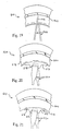
- a bicycle wheel 110 with a modified rim and spoke connection is illustrated in partial cross-sectional view and side elevational view.
- the shape of rim 124 has been changed as well as the shape of spokes 122.
- the shape of rim 124 has been changed such that space exists between exterior side surfaces of rim 124 and outer end portion 140.
- each of the spokes 122 has an outer end portion or spoke head 140 which extends into the hollow portion of rim 124 via openings 174, a substantially straight centre portion 142 extending inwardly from outer end portion 140 and an inner end portion 144 located radially inwardly of centre portion 142 such that inner end portion 144 is coupled to the hub.
- outer end portion 140, centre portion 142 and inner end portion 144 are constructed as a one-piece, unitary member with a connection member or spoke nipple 146 coupled to inner end portion 144 for connection to hub 20.
- Spokes 122 are held in openings 174 of rim 124 via contact pressure between first contact surface 156 of first end section 150 engaging the inner surface of rim 124. Moreover, in this embodiment the inner end portions 144 of spokes 122 have a threaded member 145 fixedly coupled thereto for coupling spokes 122 to hub 20 via spoke nipple 146 as seen in Figure 8a.
- this second embodiment will not be discussed or illustrated in detail herein. Rather, the description of the first embodiment discussed above should basically apply to this second embodiment.
- FIG. 9 a partial cross-sectional view of a bicycle wheel 110a is illustrated in accordance with a third embodiment of the present invention.
- the embodiment of Figure 9 is basically identical to the embodiment illustrated in Figures 7 and 8, except that the spokes 122 are permanently secured to rim 124.
- the first end sections 150 of spokes 122 are fixedly secured to the inner surface of rim 124 via fastening means 160 such as spot welds, adhesive, cement or the like.
- fastening means 160 can also be a fastener such as a rivet or a bolt and nut or the like.
- a fastener can be used in conjunction with an adhesive, cement or the like.
- this embodiment will not be discussed or illustrated in detail herein. Rather, the description of the previous embodiments explaining the present invention applies to this embodiment.
- FIG. 10 a partial cross-sectional view of a bicycle wheel 110b in accordance with the present invention is illustrated.
- This embodiment is substantially similar to the embodiments of Figures 7-9, except for the positioning of the fastening means 160.
- spokes 122 are permanently secured to the exterior surface of rim 124 via fastening means 160 such as spot welds, adhesive, cement or the like.
- fastening means 160 can also be a fastener such as a rivet or a bolt and nut or the like.
- a fastener can be used in conjunction with an adhesive, cement or the like.
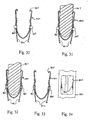
- each of the spokes 222 has an outer end portion or spoke head 240 which extends through the hollow portion of rim 224 via openings 274, a pair of straight centre portions 242 located radially inwardly of outer end portion 240 and a pair of inner end portions (not shown) located radially inwardly of centre portions 242 such that inner end portions are coupled to the hub.
- outer end portion 240, centre portions 242 and inner end portions are constructed as a one-piece, unitary member with connection members or spoke nipples coupled to inner end portions for connection to hub 20.
- inner end portions are similar in construction to inner end portions 144 as seen in Figure 8a.
- this embodiment will not be discussed or illustrated in detail herein. Rather, the description of the previous embodiments explaining the present invention applies to this embodiment.
- FIG. 13 a partial cross-sectional view of a bicycle wheel 210a is illustrated in accordance with a sixth embodiment of the present invention.
- This embodiment is similar to the embodiment illustrated in Figures 11 and 12, except that each of the spokes 222 are fixedly coupled to rim 224 via fastening means 260 such as spot welds, adhesive, cement or the like.
- fastening means 260 can also be a fastener such as a rivet or a bolt and nut or the like.
- a fastener can be used in conjunction with an adhesive, cement or the like.
- the centre portions 242 are each fixedly coupled to opposite sides of the exterior surface of the attachment portions of the rim.
- this embodiment will not be discussed or illustrated in detail herein. Rather, the description of the previous embodiments regarding the present invention should also apply to this embodiment.
- FIG. 14 a partial cross-sectional view of a bicycle wheel 210b in accordance with the present invention is illustrated.
- a plurality of spoke attachment portions or members 272b (only one shown) with opening 274 are coupled to rim 224b at equally spaced apart locations.
- a one-piece spoke 221b is utilized to form a pair of spokes 222.
- a single, annular flange may be used to form the spoke attachment portion of rim 224b.
- this embodiment will not be discussed or illustrated in detail herein. Rather, the description of the previous embodiments regarding the present invention should also apply to this embodiment.
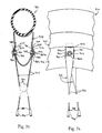
- each of the spokes 322 has an outer end portion or spoke head 340 which extends into the hollow portion of rim 324 via openings 374, a substantially straight centre portion 342 extending inwardly from outer end portion 340 and an inner end portion (not shown) located radially inwardly of centre portion 142 such that inner end portion is coupled to the hub.
- outer end portion 140, centre portions 142 and inner end portion are constructed as a one-piece, unitary member with a connection member or spoke nipple coupled to inner end portion for connection to hub 20.
- Spokes 122 are held in openings 174 of rim 124 via contact pressure between first contact surface 156 of first end section 150 engaging the inner surface of rim 124. Moreover, in this embodiment the inner end portions 144 of spokes 122 have a threaded member 145 fixedly coupled thereto for coupling spokes 122 to hub 20 via spoke nipple 146 as seen in Figure 8a.
- the attachment portions 372 are bowed outwardly to form a bulged section such that the outermost point of the attachment portions 372 are spaced farther apart than the braking portions 370.
- the bulged section of the attachment portions 372 has an axial width which is greater than the axial width between the braking portions 370. Accordingly, spokes 322 are bent along this curved section for attachment to the hub.
- this embodiment will not be discussed or illustrated in detail herein. Rather, the description of the prior embodiments of the present invention should apply to this embodiment.
- FIG. 17 a cross-sectional elevational view of a bicycle wheel 310a in accordance with a ninth embodiment of the present invention is illustrated.
- This embodiment is substantially identical to the eighth embodiment, except that the spokes 322 are permanently coupled to rim 324.
- the spokes 322 are fixedly coupled to rim 324 via fastening means 360 such as spot welds, adhesive, cement or the like.
- fastening means 360 can also be a fastener such as a rivet or a bolt and nut or the like.
- a fastener can be used in conjunction with an adhesive, cement or the like.
- spokes 322 are fixedly or permanently secured to rim 324.
- the fastening means 360 is located along the upper part of the centre portions of spokes 222 in this embodiment.
- this embodiment will not be discussed or illustrated in detail herein. Rather, the description of the features of the present invention as described in the prior embodiments should also apply to this embodiment.
- a partial cross-sectional view of a bicycle wheel 310b is illustrated for use with spokes 322.
- the spokes 222 are permanently coupled to the inner surface of rim 324 via fastening means 360 such as spot welds, adhesive, cement or the like.
- fastening means 360 can also be a fastener such as a rivet or a bolt and nut or the like.
- a fastener can be used in conjunction with an adhesive, cement or the like.
- this embodiment is identical to the prior two embodiments illustrated in Figures 14-16, except for the positioning of the welds or adhesive or fastener.
- this embodiment will not be discussed or illustrated in detail herein. Rather, the description of the prior embodiments should also apply to this embodiment.
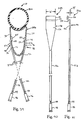
- FIG 19 a partial elevational view of a bicycle wheel 410 with a modified rim and spoke connection is illustrated.
- the cross-section of the spokes 422 (only one shown) have been changed to be substantially circular along its entire length, and the openings 474 in the rim 424 has also been made substantially circular.
- the spokes 422 can have other cross-sections with the openings 474 in the rim 424 corresponding to the cross-section of the spokes 422.
- this embodiment will not be discussed or illustrated in detail herein. Rather, the description of the prior embodiments should apply to this embodiment.
- a partial elevational view of a bicycle wheel 510 with a modified rim 524 is illustrated for use with spokes 22a of the first embodiment.
- the rim 524 is provided with a plurality of protrusions 571 (only one shown) which form a part of the attachment portions 572 of the rim 524.
- Protrusions 571 are equally spaced about the inner periphery of bicycle wheel 510 and each has a pair of openings 574 for receiving a pair of spokes 22a. Accordingly, the spokes 22a and rim 524 are coupled together in substantially the same manner as discussed above pertaining to the first embodiment of the present invention.
- this embodiment will not be discussed or illustrated in detail herein. Rather, the description of the prior embodiments should apply to this embodiment.
- a partial elevational view of a bicycle wheel 610 in accordance with a thirteenth embodiment of the present invention is illustrated in which the rim 624 of the bicycle wheel 610 has a plurality of attachment members 671 (only one shown) which form a part of attachment portions 672. Attachment members 671 are fastened to the rim 624 by fasteners 675. Attachment members 671 have a pair of openings 674 for connecting a pair of spokes 22a thereto. In other words, this embodiment illustrates that the rim 624 can be constructed of additional parts. Moreover, the spoke attachment portions 672 can be constructed of a different material from the material of the remainder of rim 624 to provide a shock absorbing type affect if needed and/or desired.
- rim 724 has a plurality of openings 774 for connecting spokes 722 thereto in a somewhat similar manner as in the first embodiment. Openings 774 are preferably equally spaced about the periphery of rim 724 and are substantially rectangular in shape. Similarly to the first embodiment, rim 724 preferably has six or eight openings 774 on each sidewall of rim 724 such that twelve or sixteen spokes 722 are connected between rim 724 and the hub.
- the outer annular surface 768 of rim 724 which receives the pneumatic tire has a plurality of access slots 777 which are sized to receive spokes 722 therethrough as explained below. Accordingly, openings 777 of outer annular surface 768 are positioned adjacent to openings 774 which are located on the sidewalls or attachment portions 772 of rim 724.
- Openings 774 preferably have a radial width of approximately 5.0 millimetres.
- the circumferential widths of openings 774 are preferably sized to be substantially equal to or slightly larger than the circumferential width of the portion of the spokes 722 located therein.
- each of the spokes 722 has an outer end portion or spoke head 740 which is received in the annular hollow area of rim 724.
- Each spoke 722 also has a centre portion 742 extending inwardly from outer end portion 740 towards the hub and has an inner end portion or connector (not shown) attached to its free end which is in turn adapted to be coupled to a bicycle wheel hub in the manner shown in the preceding embodiments.
- spoke 722 is constructed of a sheet material having a substantially uniform thickness.
- the outer end portion or spoke head 740 has a first enlarged section 741a and a narrower second section 741b such that each spoke 722 is secured within rim 724 by its first section 741a of outer portion 740 engaging opening 774 of rim 724 and second section 741b of outer portion 740 passing through opening 774 of rim 724.
- the circumferential or transverse width of first section 741a of outer end portion 740 is sized such that it passes through opening 777 of the outer annular surface 768, but is larger than the openings 774 in the attachment portions 772 of rim 724 to retain spoke 722 to rim 724.
- First section 741a of outer end portion 740 is also spot welded or adhesively secured to the inner surface of attachment portions 772 of rim 724 by a spot weld or adhesive 760 in a similar manner as discussed above.
- a fastener such as a rivet or a bolt and nut or the like can be used instead of spot weld or adhesive 760 or in conjunction therewith.
- each spoke 722 is secured within rim 724 by its outer portion 740 engaging opening 774 as well as due to the adhesive or spot weld 760 or a fastener.
- the adhesive or spot weld could be eliminated if needed and/or desired.
- the outer end portion 740 should be a substantially flat member or bent to follow the interior contour of rim 724.
- the outer end portion 740 has a large attachment area for securing to the sidewall or attachment portion 724 of rim 724 so that any stress applied to rim 724 is distributed over a larger area of rim 724.
- spoke 722 is preferably constructed of a flat sheet material that forms outer end portion 740, first centre section 741 and second centre portion 742.
- the inner end portion (not shown) which is coupled to the inner end of centre portion 742 preferably has a connection assembly similar to that shown in Figure 8a such that spoke 722 can be placed under tension.
- a bicycle wheel 810 with a slightly modified rim and spoke connection is illustrated in partial cross-sectional view and side elevational view.
- spokes 822 and rim 824 have been slightly changed.
- spokes 822 have been provided with holes 823 and rims 824 have been provided with holes 825 for receiving rivets 860.
- spokes 822 can be further coupled to rim 824 via adhesive or cement 861.
- rivets 860 can be eliminated to use only an adhesive or nothing at all as mentioned in some of the prior embodiments.
- spokes 822 can be identical to spokes 22a of the first embodiment except for the addition of holes 823 for rivets 860.
- each of the spokes 822 has an outer end portion or spoke head 840 which extends into the hollow portion of rim 824 via openings 874, a substantially straight centre portion 842 extending inwardly from outer end portion 840 and an inner end portion 844 located radially inwardly of centre portion 842 such that the inner end portion 844 is coupled to the hub in the same manner as seen in Figure 3.
- outer end portion 840, centre portion 842 and inner end portion 844 are constructed as a one-piece, unitary member with a connection member or spoke nipple 846 coupled to the inner end portion 844 for connection to hub 20 as seen in the first embodiment.
- Bicycle rim 824 is similar to the rims discussed above, except that it includes a plurality of holes 825 which are equally spaced around each side of the circumference of rim 824 to receive rivets 860.
- Bicycle rim 824 has an outer annular surface adapted to receive a tire thereon and first and second annular spoke attachment portions coupled to the outer annular surface and extending radially inwardly from the first and second annular spoke attachment portions.
- the first and second annular spoke attachment portions are coupled together at their inner ends by an inner annular surface.
- the first and second annular spoke attachment portions face in opposite directions with the spoke openings 874 formed therein and the fastener openings 825 positioned adjacent the spoke openings 874.
- the outer annular surface, the first and second annular spoke attachment portions and the inner annular surface are preferably integrally formed as a one-piece, unitary member with an annular hollow area formed therebetween.
- Rim 824 of this embodiment is somewhat similar to rim 324 of Figures 15 through 18 in that the rim 824 has a bulged section 872.
- the exterior surfaces which form bulged section 872 are located radially inwardly of spoke openings 874, while fastener openings 825 are formed along bulged section 872.
- Bulged section 872 bows outwardly such that spokes 822 are bent slightly around bulged section 872 when spokes 822 are coupled between hub 20 and rim 824.
- bulged section 872 has an axial width which is larger than the axial width of rim 824 along said spoke openings 874.
- bulged section 872 is formed by oppositely facing convex sections of the exterior surfaces of rim 824.
- the fastener openings 825 are formed along the convex sections of exterior surfaces of bulged section 872.
- Spoke openings 874 are preferably substantially elongated, thin slot extending in a substantially circumferential direction along the first and second annular spoke attachment portions.
- the spoke openings 874 are preferably located at least five millimetres radially outwardly from the inner annular surface, and having a radial width in the range of about 0.5 millimetres to about 5.0 millimetres.
- wheel 810 can be either a twelve spoked wheel as in Figure 1 or a sixteen spoked wheel as seen in Figure 2. Of course, it will be apparent to those skilled in the art from this disclosure that wheel 810 can be either a front or rear wheel having fewer or more spokes than illustrated in Figures 1 or 2.
- spokes 822 are fixedly secured to rim 824 using an anvil or support member 867 which is inserted through the access openings 865 formed in the upper surface of rim 824.
- a plurality of access openings 865 are formed in the upper surface of rim 824 for accessing the interior hollow portion of rim 824 such that rivets 860 can be inserted through the holes 823 and 825 of the spokes 822 and rim 824, respectively.
- the rivets 860 are hammered or otherwise deformed so as to form a headed portion which engages the outwardly facing surface of spokes 822 to fixedly secure spokes 822 to rim 824 as seen in Figure 32.
- anvil 867 supports the rivets 860 from being pushed inwardly into the hollow area of rim 824 during the deformation of rivets 860.
- spokes 822 are fixedly secured to rim 824 as seen in Figures 33 and 34.
- a pop-rivet could be utilized, in which case access opening 865 and anvil 867 would not be necessary.
- spokes 922 and rim 924 have been slightly changed.
- spokes 922 have been provided with holes 923 and rims 924 have been provided with holes 925 for receiving fasteners 960.
- spokes 922 can be further coupled to rim 924 via adhesive or cement 961.
- fasteners 960 can be eliminated to use only an adhesive or nothing at all as mentioned in some of the prior embodiments.
- spokes 922 can be identical to spokes 22a of the first embodiment except for the addition of holes 923 for fasteners 960.
- fasteners 960 each includes a pin 960a and a self-locking ring or retaining ring 960b.
- pin 960a is a headed pin with a shaft portion and a head portion.
- the shaft portion of pin 960a is inserted through one of the holes 925 in rim 924 and through one of the holes 923 in one of the spokes 922 such that the head portion of the pin 960a abuts against the internal surface of rim 924.
- An anvil like in the prior embodiment, can be utilized to hold pins 960a in place.
- retaining ring 960b is pushed onto the shaft portion of pin 960a to fixedly secure spoke 922 to rim 924.
- the shaft portion of pin 960a can be smooth or can include one or more ribs or grooves for more securely fastening retaining ring 960b to the shaft portion of pin 960a.
- fastener 960 could be a nut and bolt or some other type of fastener as needed and/or desired.
- the fastening ring 960b could be a C-shaped retaining ring for engaging a groove in the shaft portion of the pin.
- each of the spokes 922 has an outer end portion or spoke head 940 which extends into the hollow portion of rim 924 via openings 974, a substantially straight centre portion 942 extending inwardly from outer end portion 940 and an inner end portion 944 located radially inwardly of centre portion 942 such that the inner end portion 944 is coupled to the hub in the same manner as seen in Figure 3.
- outer end portion 940, centre portion 942 and inner end portion 944 are constructed as a one-piece, unitary member with a connection member or spoke nipple 946 coupled to the inner end portion 944 for connection to hub 20 as seen in the first embodiment.
- Rim 924 of this embodiment is somewhat similar to rim 324 of Figures 15 through 18 and rim 824 of Figures 28-34 in that the rim 924 has a bulged section 972. Bulged section 972 bows outwardly such that spokes 922 are bent slightly around bulged section 972 when spokes 922 are coupled between hub 20 and rim 924.
- the description of rims 324 and 824 applies to this embodiment to the extent that they do not contradict the drawings and/or the description thereof.
- Rim 924 is similar to the rims discussed above, except that it includes a plurality of holes 925 which are equally spaced around each side of the circumference of rim 924 to receive fasteners 960. Moreover, it will be apparent to those skilled in the art from this disclosure that wheel 910 can be either a twelve spoked wheel as in Figure 1 or a sixteen spoked wheel as seen in Figure 2. Of course, it will be apparent to those skilled in the art from this disclosure that wheel 910 can be either a front or rear wheel having fewer or more spokes than illustrated in Figures 1 or 2.
- Spokes 22a extend from the left and right ends of the hub 20a towards the rim 24a.
- six spokes extend substantially outwardly from the right end of hub 20a to rim 24a and six spokes extend substantially outwardly from the left end of hub 20a to rim 24a.
- Spokes 22a are preferably tangentially arranged relative to hub 20a as they extend outwardly therefrom.
- spokes 22a can be arranged in a more radial direction if needed and/or desired.
- each of the spokes 22a has an outer end portion 40, a center portion 42 and an inner end portion 44.
- Outer end portion or spoke head 40 is coupled to rim 24a.
- Straight center portion 42 is located radially inwardly of outer end portion 40, and inner end portion 44 located radially inwardly of the center portion 42.
- Center portion 42 is coupled to hub 20a in a relatively conventional manner.
- outer end portion 40, center portion 42 and inner end portion 44 are constructed as a unitary, one-piece member with spoke nipples 46 theadedly coupled to the inner end portion 44 of each of the spokes 22a for connection to hub 20a.
- outer end portion 40 of each spoke22a has a first predetermined width W and a first predetermined thickness T.
- the width W of outer end portion 40 of each spoke22a extends in a first direction, while the thickness T of outer end portion 40 of each spoke22a extends in a second direction, which is substantially perpendicular to the first direction.
- the outer end portion 40 has a width W that is preferably at least ten times the thickness T of the outer end portion 40.
- outer end portion 40 has a width W that is approximately thirty times the thickness T of the outer end portion 40.
- the outer end portions 40 of spokes 22a can have widths of approximately 15.0 millimeters and thicknesses of approximately 0.5 millimeters.
- outer end portions 40 of spokes 22a have an elongated cross section such as a rectangular or an elongated elliptical cross section, while center portions 42 and inner end portions 44 each have a circular or elliptical cross section.
- the entire length of spokes 22a can be substantially uniform along its entire cross section if needed and/or desired.
- constant cross section spokes can be utilized or spokes with a varying cross section can be utilized as needed and/or desired.
- spokes with an elliptical cross section could be used in accordance with the present invention.
- outer end portion 40 has a width W that is preferably at least ten times the thickness T of the outer end portion 40.
- outer end portion 40 has a width W that is at least thirty times the thickness T of the outer end portion 40.
- outer end portions 40 of spokes 22a are bent to form first sections 50 at the free ends of spokes 22a which are offset from the second sections 52.
- This offsetting of the first and second section 50 and 52 forms a bend or offset section 54 therebetween, which retains the spoke 22a to rim 24a as discussed below.
- second sections 52 of each spoke 22a lies substantially in the same plane as its respective center portion.
- First section 50 lies in a plane, which is spaced from the plane of the second section 52 and preferably parallel thereto.
- first section 50 can be bent or formed to have a different shape and/or cross section than the illustrated shapes and cross sections.
- the shapes and cross sections of first section 50, second section 52 and bend or offset section 54 of each spoke should be configured to prevent axial movement of the spoke relative to rim 24a when the spoke is in the installed position.
- first section 50 of each spoke 22a has a first contact surface 56 facing in a first direction to engage an inner surface of rim 24a.
- Second section 52 of each spoke 22a has a second contact surface 58 facing in a second direction to engage the outer surface of rim 24a.
- the lateral spacing between first contact surface 56 of first section 50 and second contact surface 58 is preferably slightly larger than the thickness of rim 24a. Accordingly, when spokes 22a are installed in rim 24a, spokes 22a engage rim 24a to prevent any substantial movement therebetween.
- additional fastening means such as an adhesive or cement or the like can be utilized to more firmly and fixedly secure outer end portions 40 of spokes 22a to the spoke attachment portions of the annular rim 24a.
- adhesive as used herein, including the claims, includes any compound or material which can be used to secure to materials together including cements and the like.
- fasteners or fastening means (not shown), such as spot welding, rivets or threaded fasteners or the like, can be utilized if needed and/or desired. Such fasteners can extend through either first contact surface 56 or second contact surface 58, and into the side portions of rim 24a.
- fasteners can be used in conjunction with adhesive or the like.
- Center portions 42 of spokes 22a are illustrated as being substantially straight wire type spokes with a substantially elliptical cross section. However, it will be apparent to those skilled in the art from this disclosure that center portions 42 of spokes 22a can be configured to have other types of cross sections and/or shapes. For example, center portions 42 can be more rectangular in cross section with the shape being uniformed along the entire length of center portion 42. Alternatively, the cross section of center portion 42 can vary along its length such that the cross section of center portion 42 becomes wider as it approaches hub 24a. In other words, the thickness and/or width of center portion 42 can be either uniformed or varied as needed and/or desired.
- Inner end portions 44 of spokes 22a are threaded for receiving conventional spoke nipples 46 thereon. More specifically, inner end portions 44 of spokes 22a are inserted through one end of bores 34a of hub 20a, and then spoke nipples 46a are inserted through the other end of bores 34a. The headed or flanged portion of the spoke nipples 46 engage an internal abutment surface of bores 34 to fixedly secure inner end portions 44 of spokes 22a to hub 20a. Accordingly, spokes 22a can be tightened in a substantially conventional manner between hub 20a and rim 24a to secure inner end portions 44 of spokes 22a thereto.
- Rim 24a is a so-called deep rim in which the rim height is greater than the rim width and is designed to have pneumatic tire 26a fastened thereto by a tire cement.
- rim 24a can have other shapes to accommodate other types of tires as needed and/or desired without departing from the scope of the present invention.
- Annular rim 24a is constructed of a substantially rigid material, such as those materials, which are well known in the art.
- rims 24a can be constructed of any suitable metallic material, such as plated steel, stainless steel, aluminum or titanium, as well as other non-metallic materials, such as a carbon fiber composite, which can be utilized for a bicycle wheel.
- Rim 24a is substantially circular as seen in side elevation ( Figure 1), and has an outer annular surface 68, a pair of annular braking portions 70 and a pair of annular spoke attachment portions 72.
- the outer annular surface 68 is adapted to receive pneumatic tire 26a thereon.
- the annular braking portions 70 are located on the sides of rim 24a.
- the annular spoke attachment portions 72 are also located on the sides of rim 24a, radially inward of annular braking portions 70 as seen in Figure 38.
- Rim 24a is a tubular member with a hollow, annular inner area. It will be apparent to those skilled in the art that the shape of outer annular surface 68 of rim 24a could be modified to accommodate different types of tires such as "clinchers" as needed and/or desired.
- outer annular surface 68 of rim 24a is designed for use with "tubular" or "sew-up" type tires which are cemented to outer annular surface 68.
- Braking portions 70 are preferably substantially flat, circular surfaces which are designed to be engaged with the brake pads of a brake device for slowing or stopping rotation of wheel 10. Braking portions 70 are preferably parallel to each other and located between outer annular surface 68 and one of the spoke attachment portions.
- Spoke attachment portions 72 are located radially inwardly relative to outer annular surface 68 and braking portions 70 of the rim 24a. Preferably, spoke attachment portions 72 are angled towards each other to form a substantially V-shaped section of rim 24a with its apex pointed towards the center of wheel 10. Each spoke attachment portion 72 has a plurality of openings 74 for receiving first sections 50 of the spokes 22a therein and a plurality of radial recesses 76 for receiving at least parts of outer portions 40 therein.
- Openings 74 and radial recesses 76 are preferably equally spaced about spoke attachment portions 72, with radial recesses 76 being located radially inwardly of openings 74.
- the plurality of openings 74 are preferably elongated openings or slots which are sized and shaped to receive the outer end portions of the spokes therein. Elongated openings 74 distribute the forces on rim 24a over a greater area than ordinary round spokes such that stress fracturing and/or tearing of rim 24a is minimized.
- openings 74 have circumferential lengths of at least approximately 5.0 millimeters.
- openings 74 preferably have circumferential lengths of approximately 17.0 millimeters and radial widths of approximately 0.7 millimeters.
- openings 74 are spaced from the innermost edge of rim 24a by at least 5.0 millimeters to increase the resistance of damage to rim 24a.
- the radial distance from the inner edge of openings 74 to the innermost edge of rim 24a is at least one third the circumferential length of opening 74. The farther openings 74 can be spaced from the inner peripheral edge of rim 24a, the stronger the connection between spokes 22a and rim 24a.
- the radial widths of openings 74a are preferably substantially equal to or slightly greater than the widths of spokes 22a so that debris, dirt and the like does not enter the hollow area of rim 24a.
- the thickness of spokes 22a at first end sections 50 is in the range of approximately 0.5 millimeters to approximately 3.0 millimeters. Accordingly, openings 74 can have a radial width in the range of approximately 0.5 millimeters to approximately 5.0 millimeters. For example, if the thickness of first end section 50 of each spoke 22a is approximately 1.0 millimeters then the radial width of each opening 74 can be approximately 1.2 millimeters.
- recesses 76 have axial depths, which are preferably substantially equal to the thickness of second section 52 of outer portion 40. This arrangement provides a more aerodynamic design to reduce air resistance.
- first end sections 50 and bend sections 54 are configured to freely pass through openings 74 of rim 24a.
- openings 74 are preferably configured to be substantially the same shape as the cross section of bend sections 54 of spokes 22a and only slightly larger as mentioned above.
- openings 74 limit circumferential movement of the bend sections 54 therein.
- the shapes and cross sections of first section 50, second section 52 and bend section 54 of each spoke should be configured to prevent axial movement of the spoke relative to rim 24a when the spoke is in the installed position.
- FIG 44 a partial cross sectional view of a bicycle rim 124 is illustrated in accordance with the present invention.
- This embodiment is substantially similar to the previous embodiment of Figures 37-43, except that the depth each of the recesses 176 has been decreased. Accordingly, the outer end portions 140 of the spokes 122 are not flush with the outer surfaces of the spoke attachment portions 172. Rather, the outer end portions 140 of the spokes 122 protrude outwardly from the outer surface of the spoke attachment portions 172.
- recesses 176 of rim 124 have axial depths, which are less than the thicknesses of second sections 152 of outer portions 140. This arrangement provides an aerodynamic design, which reduces air resistance.
- this embodiment will not be discussed or illustrated in further detail herein. Rather, the description of the parts of the previous embodiment explaining the present invention applies to this embodiment.
- FIG. 45 a partial cross-sectional view of a bicycle rim 224 is illustrated in accordance with the present invention.
- This embodiment is substantially similar to the embodiment of Figures 37-43, except that the depth each of the recesses has been increased. Accordingly, the outer end portions 240 of the spokes 222 are not flush with the outer surfaces of the spoke attachment portions 272. Rather, the outer end portions 240 of the spokes 222 are recessed from the outer surface of spoke attachment portion 272.
- recesses 276 of rim 224 have axial depths, which are greater than the thicknesses of second sections 252 of outer portions 240. This arrangement provides an aerodynamic design, which reduces air resistance.
- this embodiment will not be discussed or illustrated in detail herein. Rather, the description of the parts of the seventeenth embodiment explaining the present invention applies to this embodiment.
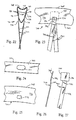
- spoke 322 is illustrated in accordance with another aspect of the present invention.
- Spokes 322 is designed to be used with either wheel 10 or 12.
- spoke 322 extends between hub 20a or 20b and rim 24a or 24b.
- spoke 322 has an outer end portion 340, a substantially straight center portion (not shown) and an inner end portion (not shown).
- outer end portion 340, center portion and inner end portion are constructed as a one-piece, unitary member with a connection member or spoke nipple coupled to inner end portion for connection to hub 20a or 20b.
- Outer end portion 340 of spokes 322 is bent to form a first section 350 and second sections 352 at the free end of spoke 322.
- This offsetting of the first and second section 350 and 352 forms a bend or offset section 354 therebetween, which retains the spoke 322 to rim 24a or 24b.
- first section 350 is offset from the second section 352 by offset section 354, which extends substantially perpendicular to first and second sections 350 and 352.
- second sections 352 of each spoke 322 lies substantially in the same plane as its respective center portion.
- First section 350 on the other hand, lies in a plane, which is spaced from the plane of the second section 352 and preferably parallel thereto.
- first section 350 can be bent or formed to have a different shape and/or cross section than the illustrated shapes and cross sections.
- the shapes and cross sections of first section 350, second section 352 and bend section 354 of each spoke should be configured to prevent axial movement of the spoke 322 relative to rim 24a or 24b, when the spoke 322 is in the installed position.
- bend or offset section 354 applies a force to rim 24a or 24b and vice-a-versa.
- bend or offset section 354 is thicker than either first section 350 or second section 352.
- additional fastening means such as an adhesive or cement or the like can be utilized to more firmly and fixedly secure outer end portions 340 of spokes 322 to the spoke attachment portions of the annular rim 24a or 24b.
- adhesive as used herein, including the claims, includes any compound or material which can be used to secure to materials together including cements and the like.
- fasteners or fastening means (not shown), such as spot welding, rivets or threaded fasteners or the like, can be utilized if needed and/or desired.
- fasteners can be used in conjunction with adhesive or the like.
- this embodiment will not be discussed or illustrated in detail herein. Rather, the description of the previous embodiments explaining the present invention applies to this embodiment.
- spoke 422 is illustrated in accordance with another aspect of the present invention.
- Spokes 422 is designed to be used with either wheel 10 or 12.
- spoke 422 extends between hub 20a or 20b and rim 24a or 24b.
- spoke 422 has an outer end portion 440, a substantially straight center portion (not shown) and an inner end portion (not shown).
- outer end portion 440, center portion and inner end portion are constructed as a one-piece, unitary member with a connection member or spoke nipple coupled to inner end portion for connection to hub 20a or 20b.
- Outer end portion 440 of spokes 422 is bent to form a first section 450 and second sections 452 at the free end of spoke 422.
- This offsetting of the first and second section 450 and 452 forms a bend or offset section 454 therebetween, which retains the spoke 422 to rim 24a or 24b.
- first section 450 is offset from the second section 452 by offset section 454, which extends substantially perpendicular to first and second sections 450 and 452.
- second sections 452 of each spoke 422 lies substantially in the same plane as its respective center portion.
- First section 450 on the other hand, lies in a plane, which is spaced from the plane of the second section 452 and preferably parallel thereto.
- first section 450 can be bent or formed to have a different shape and/or cross section than the illustrated shapes and cross sections.
- the shapes and cross sections of first section 450, second section 452 and bend section 454 of each spoke should be configured to prevent axial movement of the spoke 422 relative to rim 24a or 24b, when the spoke 422 is in the installed position.
- bend or offset section 454 applies a force to rim 24a or 24b and vice-a-versa.
- bend or offset section 454 is corrugated for additional strength.
- the effective thickness of offset section 454 is greater than the effective thickness of either first section 450 or second section 452.
- additional fastening means such as an adhesive or cement or the like can be utilized to more firmly and fixedly secure outer end portions 440 of spokes 422 to the spoke attachment portions of the annular rim 24a or 24b.
- adhesive as used herein, including the claims, includes any compound or material which can be used to secure to materials together including cements and the like.
- fasteners or fastening means (not shown), such as spot welding, rivets or threaded fasteners or the like, can be utilized if needed and/or desired.
- fasteners can be used in conjunction with adhesive or the like.
- this embodiment will not be discussed or illustrated in detail herein. Rather, the description of the previous embodiments explaining the present invention applies to this embodiment.
Landscapes
- Engineering & Computer Science (AREA)
- Mechanical Engineering (AREA)
- Tires In General (AREA)
- Connection Of Plates (AREA)
- Motorcycle And Bicycle Frame (AREA)
Priority Applications (2)
| Application Number | Priority Date | Filing Date | Title |
|---|---|---|---|
| EP03000031A EP1300262B1 (de) | 1997-11-13 | 1998-11-03 | Fahrradrad |
| EP03000030A EP1300260B1 (de) | 1997-11-13 | 1998-11-03 | Fahrradrad |
Applications Claiming Priority (6)
| Application Number | Priority Date | Filing Date | Title |
|---|---|---|---|
| US969607 | 1992-10-30 | ||
| US08/969,607 US6068347A (en) | 1997-11-13 | 1997-11-13 | Bicycle wheel |
| US09/027,293 US6158819A (en) | 1997-11-13 | 1998-02-20 | Bicycle wheel |
| US27293 | 1998-02-20 | ||
| US108300 | 1998-07-01 | ||
| US09/108,300 US6068348A (en) | 1997-11-13 | 1998-07-01 | Bicycle wheel |
Related Child Applications (2)
| Application Number | Title | Priority Date | Filing Date |
|---|---|---|---|
| EP03000030A Division EP1300260B1 (de) | 1997-11-13 | 1998-11-03 | Fahrradrad |
| EP03000031A Division EP1300262B1 (de) | 1997-11-13 | 1998-11-03 | Fahrradrad |
Publications (3)
| Publication Number | Publication Date |
|---|---|
| EP0916520A2 true EP0916520A2 (de) | 1999-05-19 |
| EP0916520A3 EP0916520A3 (de) | 2001-01-03 |
| EP0916520B1 EP0916520B1 (de) | 2004-03-17 |
Family
ID=27362974
Family Applications (1)
| Application Number | Title | Priority Date | Filing Date |
|---|---|---|---|
| EP98308966A Expired - Fee Related EP0916520B1 (de) | 1997-11-13 | 1998-11-03 | Fahrradrad |
Country Status (9)
| Country | Link |
|---|---|
| EP (1) | EP0916520B1 (de) |
| JP (1) | JP3314044B2 (de) |
| CN (3) | CN1491814A (de) |
| CZ (1) | CZ288193B6 (de) |
| DE (3) | DE69829513T2 (de) |
| PL (1) | PL329675A1 (de) |
| RU (1) | RU2222436C2 (de) |
| SK (1) | SK284528B6 (de) |
| TW (1) | TW416915B (de) |
Cited By (6)
| Publication number | Priority date | Publication date | Assignee | Title |
|---|---|---|---|---|
| US6474746B2 (en) | 2000-03-03 | 2002-11-05 | Campagnolo Srl | Bicycle wheel rim |
| EP1068963A3 (de) * | 1999-07-13 | 2003-07-30 | Shimano Inc. | Fahrradrad mit verstärkter Felge |
| EP1068964A3 (de) * | 1999-07-13 | 2003-07-30 | Shimano Inc. | Fahrradrad mit verstärkter Felge |
| EP1818182A1 (de) * | 2006-02-11 | 2007-08-15 | Kinlin Industrial Corporation | Fahrradfelge mit mehreren einfach montierbaren Speichen |
| US9428006B2 (en) | 2009-11-25 | 2016-08-30 | Corima | Composite wheel, in particular for a cycle, and method for manufacturing such a wheel |
| CN113942340A (zh) * | 2021-11-26 | 2022-01-18 | 厦门银贝斯体育用品有限公司 | 一种整体式辐条组件与花鼓的连接结构及车轮的生产工艺 |
Families Citing this family (11)
| Publication number | Priority date | Publication date | Assignee | Title |
|---|---|---|---|---|
| EP1559581B1 (de) * | 2004-01-27 | 2008-03-12 | Campagnolo S.R.L. | Speiche für Fahrradrad und Fahrradrad eine solche Speiche enthaltend sowie Herstellverfahren für eine solche Speiche |
| EP1559583B1 (de) * | 2004-01-27 | 2009-06-17 | Campagnolo S.R.L. | Speiche für ein Fahrrad, Rad und Verfahren zur Herstellung einer solchen Speiche |
| US8746808B2 (en) * | 2011-02-14 | 2014-06-10 | Shimano Components (Malaysia) Sdn. Bhd. | Bicycle rim |
| CN104136234B (zh) * | 2012-03-07 | 2016-08-10 | 莎皮姆公司 | 用于车轮辐条的自锁螺纹接头及制造该自锁螺纹接头的方法和装置 |
| RU2524269C2 (ru) * | 2012-06-22 | 2014-07-27 | Федеральное государственное бюджетное образовательное учреждение высшего профессионального образования "Псковский государственный университет" | Колесо с внутренним подрессориванием |
| DE102013012101A1 (de) * | 2013-07-19 | 2015-01-22 | Matthias Kübler | Systemlaufrad für ein Fahrrad |
| JP6537055B2 (ja) | 2013-08-05 | 2019-07-03 | ムベア カルボ テック ゲーエムベーハーMubea Carbo Tech Gmbh | 繊維強化プラスチック材で作られたホイール |
| CN106142971A (zh) * | 2015-04-02 | 2016-11-23 | 詹存忠 | 快捷方便装卸车轮辐条 |
| DE102018127835A1 (de) * | 2018-11-07 | 2020-05-07 | Top Venturer International Limited | Fahrradspezifische Felgenkonstruktion |
| CN113291094B (zh) * | 2021-06-09 | 2023-02-03 | 中国科学院长春应用化学研究所 | 用于接合非充气轮胎的轮辐与轮辋的固定装置 |
| WO2023089627A1 (en) * | 2021-11-22 | 2023-05-25 | Tvs Motor Company Limited | A wheel structure for a saddle type vehicle |
Citations (1)
| Publication number | Priority date | Publication date | Assignee | Title |
|---|---|---|---|---|
| EP0786360A2 (de) | 1996-01-26 | 1997-07-30 | Shimano Inc. | Fahrradnabe |
Family Cites Families (6)
| Publication number | Priority date | Publication date | Assignee | Title |
|---|---|---|---|---|
| US1450064A (en) * | 1920-12-13 | 1923-03-27 | Flannery Bolt Co | Wheel structure |
| FR1332603A (fr) * | 1962-05-24 | 1963-07-19 | Michelin & Cie | Perfectionnement aux jantes moulées non métalliques pour roues à rayons |
| FR2526374A1 (fr) * | 1982-05-10 | 1983-11-10 | Michelin & Cie | Roue pour engin de moto-cross |
| US4529253A (en) * | 1983-06-10 | 1985-07-16 | Ho Wei K | Bicycle wheel, hub and spoke assembly |
| JPS6012315A (ja) * | 1983-06-30 | 1985-01-22 | Yamaha Motor Co Ltd | ワイヤスポ−ク車輪 |
| US5452945A (en) * | 1993-10-12 | 1995-09-26 | Schlanger; Raphael | Vehicle wheel |
-
1998
- 1998-11-03 DE DE69829513T patent/DE69829513T2/de not_active Expired - Fee Related
- 1998-11-03 DE DE69828534T patent/DE69828534T2/de not_active Expired - Fee Related
- 1998-11-03 DE DE69822400T patent/DE69822400T2/de not_active Expired - Fee Related
- 1998-11-03 EP EP98308966A patent/EP0916520B1/de not_active Expired - Fee Related
- 1998-11-09 SK SK1547-98A patent/SK284528B6/sk unknown
- 1998-11-10 JP JP31927398A patent/JP3314044B2/ja not_active Expired - Fee Related
- 1998-11-11 CZ CZ19983661A patent/CZ288193B6/cs not_active IP Right Cessation
- 1998-11-12 CN CNA021406375A patent/CN1491814A/zh active Pending
- 1998-11-12 CN CNA021406359A patent/CN1491813A/zh active Pending
- 1998-11-12 CN CNA021406383A patent/CN1491816A/zh active Pending
- 1998-11-13 PL PL98329675A patent/PL329675A1/xx unknown
- 1998-11-13 TW TW087118963A patent/TW416915B/zh not_active IP Right Cessation
- 1998-11-13 RU RU98120444/11A patent/RU2222436C2/ru not_active IP Right Cessation
Patent Citations (1)
| Publication number | Priority date | Publication date | Assignee | Title |
|---|---|---|---|---|
| EP0786360A2 (de) | 1996-01-26 | 1997-07-30 | Shimano Inc. | Fahrradnabe |
Cited By (7)
| Publication number | Priority date | Publication date | Assignee | Title |
|---|---|---|---|---|
| EP1068963A3 (de) * | 1999-07-13 | 2003-07-30 | Shimano Inc. | Fahrradrad mit verstärkter Felge |
| EP1068964A3 (de) * | 1999-07-13 | 2003-07-30 | Shimano Inc. | Fahrradrad mit verstärkter Felge |
| US6474746B2 (en) | 2000-03-03 | 2002-11-05 | Campagnolo Srl | Bicycle wheel rim |
| EP1818182A1 (de) * | 2006-02-11 | 2007-08-15 | Kinlin Industrial Corporation | Fahrradfelge mit mehreren einfach montierbaren Speichen |
| US9428006B2 (en) | 2009-11-25 | 2016-08-30 | Corima | Composite wheel, in particular for a cycle, and method for manufacturing such a wheel |
| CN113942340A (zh) * | 2021-11-26 | 2022-01-18 | 厦门银贝斯体育用品有限公司 | 一种整体式辐条组件与花鼓的连接结构及车轮的生产工艺 |
| CN113942340B (zh) * | 2021-11-26 | 2023-12-05 | 厦门银贝斯体育用品有限公司 | 一种整体式辐条组件与花鼓的连接结构及车轮的生产工艺 |
Also Published As
| Publication number | Publication date |
|---|---|
| SK284528B6 (sk) | 2005-05-05 |
| SK154798A3 (en) | 1999-07-12 |
| DE69828534T2 (de) | 2005-12-29 |
| JPH11208201A (ja) | 1999-08-03 |
| RU2222436C2 (ru) | 2004-01-27 |
| DE69822400T2 (de) | 2005-02-17 |
| JP3314044B2 (ja) | 2002-08-12 |
| CZ366198A3 (cs) | 1999-06-16 |
| CN1491814A (zh) | 2004-04-28 |
| DE69829513T2 (de) | 2006-04-13 |
| TW416915B (en) | 2001-01-01 |
| PL329675A1 (en) | 1999-05-24 |
| EP0916520A3 (de) | 2001-01-03 |
| DE69829513D1 (de) | 2005-04-28 |
| DE69822400D1 (de) | 2004-04-22 |
| CN1491813A (zh) | 2004-04-28 |
| EP0916520B1 (de) | 2004-03-17 |
| CZ288193B6 (en) | 2001-05-16 |
| DE69828534D1 (de) | 2005-02-10 |
| CN1491816A (zh) | 2004-04-28 |
Similar Documents
| Publication | Publication Date | Title |
|---|---|---|
| EP1300262B1 (de) | Fahrradrad | |
| US6068347A (en) | Bicycle wheel | |
| EP0916520B1 (de) | Fahrradrad | |
| EP1016553B1 (de) | Fahrradrad | |
| US7090307B2 (en) | Bicycle rim | |
| US6409282B1 (en) | Bicycle hub | |
| US7464994B2 (en) | Bicycle rim reinforced with a continuously extending resin material | |
| US6692086B2 (en) | Bicycle wheel | |
| US6568766B1 (en) | Bicycle rim | |
| US6588853B2 (en) | Bicycle rim | |
| US6736462B1 (en) | Bicycle rim | |
| EP1068964B1 (de) | Fahrradrad mit verstärkter Felge | |
| EP1068963B1 (de) | Fahrradrad mit verstärkter Felge | |
| EP1486352A2 (de) | Fahrradfelge | |
| EP1475245B1 (de) | Fahrradfelge |
Legal Events
| Date | Code | Title | Description |
|---|---|---|---|
| PUAI | Public reference made under article 153(3) epc to a published international application that has entered the european phase |
Free format text: ORIGINAL CODE: 0009012 |
|
| 17P | Request for examination filed |
Effective date: 19981120 |
|
| AK | Designated contracting states |
Kind code of ref document: A2 Designated state(s): DE FR GB IT |
|
| AX | Request for extension of the european patent |
Free format text: AL;LT;LV;MK;RO;SI |
|
| PUAL | Search report despatched |
Free format text: ORIGINAL CODE: 0009013 |
|
| AK | Designated contracting states |
Kind code of ref document: A3 Designated state(s): AT BE CH CY DE DK ES FI FR GB GR IE IT LI LU MC NL PT SE |
|
| AX | Request for extension of the european patent |
Free format text: AL;LT;LV;MK;RO;SI |
|
| AKX | Designation fees paid |
Free format text: DE FR GB IT |
|
| 17Q | First examination report despatched |
Effective date: 20020816 |
|
| GRAP | Despatch of communication of intention to grant a patent |
Free format text: ORIGINAL CODE: EPIDOSNIGR1 |
|
| GRAS | Grant fee paid |
Free format text: ORIGINAL CODE: EPIDOSNIGR3 |
|
| GRAA | (expected) grant |
Free format text: ORIGINAL CODE: 0009210 |
|
| AK | Designated contracting states |
Kind code of ref document: B1 Designated state(s): DE FR GB IT |
|
| REG | Reference to a national code |
Ref country code: GB Ref legal event code: FG4D |
|
| REF | Corresponds to: |
Ref document number: 69822400 Country of ref document: DE Date of ref document: 20040422 Kind code of ref document: P |
|
| PGFP | Annual fee paid to national office [announced via postgrant information from national office to epo] |
Ref country code: GB Payment date: 20041022 Year of fee payment: 7 |
|
| PGFP | Annual fee paid to national office [announced via postgrant information from national office to epo] |
Ref country code: FR Payment date: 20041105 Year of fee payment: 7 |
|
| PGFP | Annual fee paid to national office [announced via postgrant information from national office to epo] |
Ref country code: DE Payment date: 20041130 Year of fee payment: 7 |
|
| ET | Fr: translation filed | ||
| PLBE | No opposition filed within time limit |
Free format text: ORIGINAL CODE: 0009261 |
|
| STAA | Information on the status of an ep patent application or granted ep patent |
Free format text: STATUS: NO OPPOSITION FILED WITHIN TIME LIMIT |
|
| 26N | No opposition filed |
Effective date: 20041220 |
|
| PG25 | Lapsed in a contracting state [announced via postgrant information from national office to epo] |
Ref country code: IT Free format text: LAPSE BECAUSE OF NON-PAYMENT OF DUE FEES Effective date: 20051103 Ref country code: GB Free format text: LAPSE BECAUSE OF NON-PAYMENT OF DUE FEES Effective date: 20051103 |
|
| PG25 | Lapsed in a contracting state [announced via postgrant information from national office to epo] |
Ref country code: DE Free format text: LAPSE BECAUSE OF NON-PAYMENT OF DUE FEES Effective date: 20060601 |
|
| GBPC | Gb: european patent ceased through non-payment of renewal fee |
Effective date: 20051103 |
|
| PG25 | Lapsed in a contracting state [announced via postgrant information from national office to epo] |
Ref country code: FR Free format text: LAPSE BECAUSE OF NON-PAYMENT OF DUE FEES Effective date: 20060731 |
|
| REG | Reference to a national code |
Ref country code: FR Ref legal event code: ST Effective date: 20060731 |