EP0913697B1 - Elektrische Fehlerstromdetektoranordnung für Elektromobile - Google Patents
Elektrische Fehlerstromdetektoranordnung für Elektromobile Download PDFInfo
- Publication number
- EP0913697B1 EP0913697B1 EP98120566A EP98120566A EP0913697B1 EP 0913697 B1 EP0913697 B1 EP 0913697B1 EP 98120566 A EP98120566 A EP 98120566A EP 98120566 A EP98120566 A EP 98120566A EP 0913697 B1 EP0913697 B1 EP 0913697B1
- Authority
- EP
- European Patent Office
- Prior art keywords
- signal
- detecting
- voltage
- electric leak
- current
- Prior art date
- Legal status (The legal status is an assumption and is not a legal conclusion. Google has not performed a legal analysis and makes no representation as to the accuracy of the status listed.)
- Expired - Lifetime
Links
- 239000003990 capacitor Substances 0.000 claims description 11
- 238000002955 isolation Methods 0.000 claims 1
- 238000000034 method Methods 0.000 description 42
- 230000010354 integration Effects 0.000 description 8
- 238000001514 detection method Methods 0.000 description 7
- 238000009413 insulation Methods 0.000 description 3
- 230000003321 amplification Effects 0.000 description 1
- 230000001419 dependent effect Effects 0.000 description 1
- 238000010586 diagram Methods 0.000 description 1
- 238000010292 electrical insulation Methods 0.000 description 1
- 230000006870 function Effects 0.000 description 1
- 239000000463 material Substances 0.000 description 1
- 230000015654 memory Effects 0.000 description 1
- 238000012544 monitoring process Methods 0.000 description 1
- 238000003199 nucleic acid amplification method Methods 0.000 description 1
- 238000005070 sampling Methods 0.000 description 1
- 230000035939 shock Effects 0.000 description 1
- 230000011664 signaling Effects 0.000 description 1
Images


Classifications
-
- G—PHYSICS
- G01—MEASURING; TESTING
- G01R—MEASURING ELECTRIC VARIABLES; MEASURING MAGNETIC VARIABLES
- G01R31/00—Arrangements for testing electric properties; Arrangements for locating electric faults; Arrangements for electrical testing characterised by what is being tested not provided for elsewhere
- G01R31/005—Testing of electric installations on transport means
- G01R31/006—Testing of electric installations on transport means on road vehicles, e.g. automobiles or trucks
- G01R31/007—Testing of electric installations on transport means on road vehicles, e.g. automobiles or trucks using microprocessors or computers
-
- G—PHYSICS
- G01—MEASURING; TESTING
- G01R—MEASURING ELECTRIC VARIABLES; MEASURING MAGNETIC VARIABLES
- G01R31/00—Arrangements for testing electric properties; Arrangements for locating electric faults; Arrangements for electrical testing characterised by what is being tested not provided for elsewhere
- G01R31/50—Testing of electric apparatus, lines, cables or components for short-circuits, continuity, leakage current or incorrect line connections
- G01R31/52—Testing for short-circuits, leakage current or ground faults
Definitions
- the present invention relates to an electric leak detecting apparatus for detecting an electric leak caused by deteriorated insulation between vehicle body and battery pack in an electric motorcar provided with a high voltage battery pack insulated from the vehicle body electrically to prevent electrical shocks.
- An electric motorcar which uses an electric power as its driving source, is provided with a battery pack composed as a closed circuit and separated from the vehicle body.
- the battery pack functions as a ground to prevent electric shocks to be caused by a high voltage set battery used as a driving power source. If the insulating characteristics of the battery pack are deteriorated due to a change of the material quality thereof and/or deposit thereon, however, the high voltage battery pack is connected electrically to the vehicle body. And, this may cause a person to have an electric shock when he/she touches the vehicle body. Because, a leak current from the battery pack flows through him/her body.
- An electric leak is a sum of leak currents flowing in all insulated portions. It is thus difficult to identify a system in which the current flows through.
- an AC method which detects an electric leak resistance by applying an AC signal to an object vehicle body insulated from direct currents by a condenser and a transformer
- a non-insulating DC method which measures an electric leak resistance as a direct current without using any of the condenser and the transformer.
- the official report of Unexamined Published Japanese Patent Application No.57-119263 has disclosed an embodiment that adopts the AC method that uses a transformer
- the official report of Unexamined Published Japanese Patent Application No.60-262069 has disclosed an embodiment that adopts the DC method.
- Fig.20 shows an equivalent circuit from which an electric leak is detected.
- an electric leak should be modeled with a distributed constant concept. If it is taken into consideration that a current leaks from the potential node of every set battery, however, the equivalent circuit of the battery pack 3 is represented by the set battery 3a and an electric leak admittance 3b noted by a concentrated constant using a resistor and a condenser.
- I0 to In are leak currents, each flowing from a node to the vehicle body. The sum I of the leak currents is thus equal to the sum of the currents I0 to In because of the superposition theory of currents.
- the admittance between the vehicle ground and the set battery 3a can be represented as the sum of admittance elements.
- the battery pack 3 shown in Fig.20 can further be simplified as an AC equivalent circuit as shown in Fig.21 .
- the AC method when used for detecting electric leaks, is characterized as follows:
- the electric leak judgment will include an error due to the floating capacity Cs.
- the phase angle ⁇ must be reduced.
- the detecting signal frequency must be lowered to reduce the phase angle ⁇ .
- the DC method can solve the problems caused by the AC method described in (1) to (4).
- the AC method cannot solve a problem that the measuring accuracy is still low due to an error of the electric leak resistance of the battery pack itself. Further there is such problem that the detection side and driving side are connected with direct current on account of the detection.
- Document EP 0 751 396 A1 discloses a device for monitoring and signalling the absence of electrical insulation between a traction unit and a bodywork in electric vehicles.
- the device comprises: an AC voltage generator to be connected between the traction unit and the bodywork; means for detecting the current flowing in the voltage generator; and means for determining leakage resistance on the basis of the current and the AC voltage generated by the generator.
- the current is detected by means of a shunt resistor arranged in series with the voltage generator and a calibrated voltmeter arranged in parallel with the shunt resistor.
- the shunt resistor is decoupled from the traction unit by means of a capacitor.
- an AC signal can be used to detect an electric leak resistance in safe. Since it is no need to use a lower frequency compulsorily to improve the detection accuracy, any frequency easy to handle can be used. It is thus possible to improve the responsibility and reduce the size of the electric leak detecting apparatus.
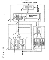
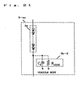
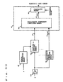
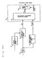
- Fig.1 is a block diagram of an electric leak detecting apparatus. At first, the components of the apparatus will be described.
- 1 is an AC signal source used to generate an AC signal.
- 2 is a capacitor (in the following: condenser) used to insulate an electric leak detecting circuit from a battery pack 3-ac and supply an AC voltage to the battery pack 3-ac.
- the battery pack 3-ac is composed of an AC equivalent circuit.
- 3a is a high voltage set battery and 3b is an electric leak admittance noted by a concentrated parameter representation between the battery pack and the vehicle body.
- 4 is phase discriminating means for converting a phase difference between the AC current i of the AC signal source 1 and the AC voltage v to a voltage V ⁇ .
- admittance detecting means for outputting a voltage
- 6 is electric leak judging means composed of resistance component computing means 6a and comparing means 6b. A real part of an admittance, that is an electric leak resistance component is obtained from the voltage V ⁇ equivalent to a phase difference and the admittance absolute value by using the resistance component computing means 6a, and then the obtained resistance component is compared with an electric leak reference value by using the comparing means 6b.
- the admittance of the whole portion between the AC signal source 1 and the vehicle body is equal to 3b shown in Fig.20 and it is indicated by a complex vector as shown in Fig. 23 .
- the admittance Y of the whole portion becomes as shown in (Expression 7).
- the voltage v is obtained by dividing the voltage vin by the condenser 2 and the electric leak admittance 3b-2, that is,
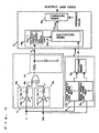
- C S ⁇ C D The phase and the amplitude can thus be regarded to be almost equal between the voltage v and the voltage vin. Consequently, the voltage v may be measured via the insulation amplifying means 16. It is also possible to substitute the voltage v for the voltage vin as shown in Fig. 3 . This means that it is only needed to measure the voltage at the side of the AC signal source 1 and it is no need to measure the voltage at such side of the condenser 2 on the set battery side which is of the high voltage and dangerous.
- the amplitude reduced by the above voltage-dividing may also be obtained by using the v' in the expression 18.
- v ⁇ in C S + C D C S • v in
- Figs.2 to 13 show a configuration of the electric leak detecting apparatus when both voltages v and vin are used.
- the phase discriminating means 4 is used to convert the phase difference between the AC current i of the AC signal source 1 and the AC voltage v to a voltage V ⁇ .
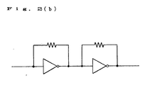
- the phase discriminating means 4 as shown in Fig. 2(a) , can be composed of a voltage comparing circuit 4a, an exclusive-or circuit 4b, and an integration circuit 4c.
- the voltage comparing circuit 4a is composed of a comparator 4a-1 used to compare a potential with another, as well as a resistor 4a-2.
- the comparator 4a-1 is used as a saturation-amplifier to detect the phase difference between the current i and the voltage v more effectively.
- the comparator 4a-1 may be composed of a high amplification factor amplifier as shown in Fig.2(b) .
- 4b is an exclusive-or circuit and 4c is an integration circuit composed of a resistor and a condenser and used to average the output voltage from the exclusive-or circuit 4b so as to find the voltage V ⁇ which is equivalent to the phase difference between the AC current i and the AC voltage v.
- the resistor 4a-2 is not a core part of the phase discrimination precedure, so it is omissible.
- the integration circuit 4c is used to convert a result of phase comparison to a voltage V ⁇ , it may be replaced with a digital circuit that can detect and output a duty ratio accurately.
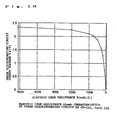
- Figs.17 and 18 show the waveforms of the rectified AC current i', the AC voltage v', and the output voltage Vf from the phase discriminating means 4 during operation when RLEAK is 100k ⁇ , 51k ⁇ , 10k ⁇ , or 1k ⁇ .
- Fig.19 shows output voltage characteristics of the phase discriminating means 4 when the electric leak resistance RLEAK is changed under the above conditions.
- the horizontal axis is a time and the vertical axis is a voltage or a current.
- the current i flowing in the electric leak admittance 3b-2 is detected by the current detecting means 9 and the current i and the AC voltage v are converted to effective value by calculating a root-mean-square respectively by the effective value converting means 5a and furthermore, the effective current value
- the means for obtaining the current i may be inserted in any position in the system composed of the AC voltage generating means 1, the condenser (Cd), and the electric leak admittance 3b-2 and then the position is not restricted to the configuration of the FIG. 1 . If the current i is to be measured indirectly using a transformer, etc., the current obtaining means may be inserted on the set battery 3a side when viewing it from the condenser (Cd).
- can be found more easily than by using the effective value by such manner that a peak value of the voltage of the AC signal source 1 and a peak value of the current i flowing in the condenser 2 is detected by peak detecting means 5c instead of using the effective value converting means 5a and the peak value of the current i is divided by the peak value of the voltage of the AC signal source 1 by dividing means 5b.
- the voltage cosine converting means 6a-1 obtains a cosine of the phase difference ⁇ from the voltage V ⁇ corresponding to the phase difference ⁇ by using a reference table which stores the correspondance between the voltage V ⁇ and the cosine beforehand , and the multiplying means 6a-2 multiplies the cosine by the admittance
- the electric leak resistance RLEAK is compared with the electric leak resistance reference value in the comparing means 6b thereby to judge existence of an electric leak.
- the electric leak judging means 6 can be composed of an analog-digital converting circuit and a microcomputer.
- the voltage-cosine converting circuit 6a-1 may be composed of a reference table composed of memories as described above, as well as a microcomputer used for computing.
- Fig.19 shows the output voltage characteristics of the phase discriminating means 4 when the electric leak resistance is changed within 500k ⁇ to 1k ⁇ .
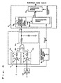
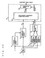
- Figs.10 and 11 show an electric leak detecting apparatus in accordance with the present invention.
- 4 is a phase discriminating means used to extract a phase difference from between the current i and the voltage v as described above.
- 6c is a converting means used to find a tangent tan ⁇ of the phase voltage Vf.
- 6d is resistance component computing means used to compute the resistance component
- Y Re ⁇ al ⁇ ⁇ C D ⁇ tan ⁇ + ⁇ ⁇ C D tan ⁇ 2 - 4 ⁇ ⁇ 2 ⁇ C S ⁇ C S + C D 2 6b is a comparing means used to compare an electric leak value with a predetermined reference value to judge an electric leak as described above. Consequently, the admittance detecting mans 5 is omissible.
- Fig.11 shows a case in which vin is used.
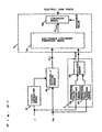
- Figs. 12 and 13 show means for estimating a floating capacity Cs in the embodiment of the present invention.
- the floating capacity Cs is estimated in this embodiment thereby to detect an electric leak more accurately.
- 15a is peak detecting means used to hold the peak values of both AC voltage and AC current.
- 15b is Cs estimating means used to estimate the floating capacity Cs in accordance with (Expression 4).
- the computing means of the Cs estimating means 15b may be replaced with a reference table.
- 15 is means for estimating a floating capacity.
- Fig. 13 shows a case in which vin is used.
- the floating capacity Cs can be decided accurately thereby to improve the accuracy of the electric leak detection, although both condenser Cd and floating capacity Cs were handled as known values in the processing for estimating a resistance component from an electric leak admittance in the previous embodiments.
- the 4f is a timing generating means which generates edge output at a zero-cross of negative to positive of AC current flowing through the condenser 2
- 4g is sample/hold means which samples and holds a voltage of the AC source 1 according to the timing output from the timing generating means 4f.
- the 6e is a resistance component detecting means which detects a leak resistance GLEAK according to the expression 17 by using the admittance
- the operation of this configuration is follow.
- the voltage v of the AC source 1 which is sampled and held at the timing of the timing generating means 4f is divided by the amplitude of the ARC signal, to obtain a reactance
- the resistance detecting means 6e calculates the inverse of the leak resistance GLEAK according to the expression 17 from the reactance
- the comparing means 6b compares it with a threshold value to judge the leak state.
- the dividing means 5b can be omitted by making the effective value or peak value of the AC source 1 as unit size.
- a band-pass filter 17 which can cut noises in bands other than that of the detecting signal from the AC signal generating means 1. If a noise frequency band is close to comparatively a high frequency, the band-pass filter may be replaced with a low-pass filter.
- Fig.14 shows a configuration of an electric leak detecting apparatus, which adopts the DC method.
- 3 is a battery pack as described in Fig.20
- 3a is n pieces of batteries disposed serially as described above.
- 3b is an electric leak admittance noted by a concentrated constant.
- 11 is a DC voltage source used to generate a DC voltage V.
- 12 is a polarity switch used to reverse the polarity of the DC voltage source 11.
- 13 is means for detecting a DC current.
- 14 is a resistor whose value is a known RK ⁇ .
- the current detecting means 13 measures the DC current IA as shown in (Expression 13).
- I A 1 1 + R K R 1 ⁇ R 2 / / R 2 ⁇ R 0 / / R 0 ⁇ R 1 ⁇ R 0 ⁇ R 1 ⁇ R 2 V ⁇ R 1 ⁇ R 2 + R 2 ⁇ R 0 + R 0 ⁇ R 1 - R 0 ⁇ R 2 ⁇ V 0 - R 0 ⁇ R 1 ⁇ V 0 + V 1
- Each double slash in (Expression 13), (Expression 14), and (Expression 16) means a parallel connection of resistors.
- V is thus erased. And, since the value of the resistor 14 is already known as RK ⁇ , the ohm value is subtracted to find the residual value as an electric leak resistance.
- the same electric leak resistance can also be obtained with the same computation as the above one even when the voltage V is applied to every node including the maximum potential 3a of the set battery 3a. This is because the internal resistance of the battery is much smaller than the electric leak resistance. Consequently, the DC method is not affected by the capacity components C0 to Cn of an inverse number of the admittance as well as not affected by the voltage of the set battery.
- the current detecting means 13 in the circuit may be positioned anywhere in the system composed of the resistor 14, the DC voltage source 11, and the vehicle body,that is the position is not limited only at the position shown in Fig.14 because the current detecting means 13 is just required to detect the current of the DC voltage source 11, which flows through the resistor 14.
Landscapes
- Engineering & Computer Science (AREA)
- Physics & Mathematics (AREA)
- General Physics & Mathematics (AREA)
- Computer Hardware Design (AREA)
- Microelectronics & Electronic Packaging (AREA)
- Chemical & Material Sciences (AREA)
- Combustion & Propulsion (AREA)
- Testing Of Short-Circuits, Discontinuities, Leakage, Or Incorrect Line Connections (AREA)
- Measurement Of Resistance Or Impedance (AREA)
Claims (4)
- Kriechstrom-Erfassungsvorrichtung, die für ein Elektro-Kraftfahrzeug eingesetzt wird, dessen Batterieteil gegenüber der Fahrzeugkarosserie in Bezug auf Gleichströme isoliert ist, wobei die Vorrichtung umfasst:eine erste Wechselstromsignal-Erzeugungseinrichtung (1) zum Erzeugen eines Wechselstromsignals und zum Zuführen eines Sinuswellen-Erfassungssignals S1 einer einzelnen Frequenz f1 zwischen die Fahrzeugkarosserie (3-ac) und eine Potentialseite des Batterieteils (3a), wobei die Potentialseite eine Niedrigpotentialseite oder eine Hochpotentialseite des Batterieteils (3a) ist;einen Kondensator (2) mit einer Kapazität CD zum Isolieren der ersten Wechselstromsignal-Erzeugungseinrichtung (1) gegenüber der Potentialseite des Batterieteils (3a) in Bezug auf Gleichströme sowie zum Verbinden der ersten Wechselstromsignal-Erzeugungseinrichtung (1) mit der Potentialseite des Batterieteils (3a) in Bezug auf Wechselströme, wobei das Erfassungssignal S1 der Potentialseite zugeführt wird;eine erste Spannungserfassungseinrichtung zum Erfassen einer Wechselstromsignal-Spannung v1 des Erfassungssignals S1 entweder an einer Seite des Kondensators (2) oder an der anderen Seite des Kondensators (2); undeine erste Stromerfassungseinrichtung (9) zum Erfassen eines Wechselstromsignal-Stroms i1 des Erfassungssignals S1;gekennzeichnet durcheine Phasenunterscheidungseinrichtung (4) zum Ermitteln einer Phasendifferenz φ zwischen der Wechselstromsignal-Spannung v1 und dem Wechselstromsignal-Strom i1 des Erfassungssignals S1;eine Tangens-Erfassungseinrichtung (6c) zum Berechnen eines Tangens tan φ der Phasendifferenz φ;eine zweite Wechselstromsignal-Erzeugungseinrichtung zum Erzeugen eines Wechselstromsignals und zum Zuführen eines Erfassungssignals S2, das ein Sinuswellensignal einer einzelnen Frequenz f2 ist, zwischen die Fahrzeugkarosserie und die Potentialseite des Batterieteils, wobei die Frequenz f2 höher ist als die Frequenz f1;wobei die zweite Wechselstromsignal-Erzeugungseinrichtung gegenüber der Potentialseite des Batterieteils in Bezug auf Gleichströme durch den Kondensator (2) isoliert ist,eine zweite Spannungserfassungseinrichtung (15a) zum Erfassen einer Wechselstromsignal-Spannung v2 des Erfassungssignals S2 entweder an einer Seite des Kondensators (2) oder an der anderen Seite des Kondensators (2);eine zweite Stromerfassungseinrichtung (17a) zum Erfassen eines Wechselstromsignal-Stroms i2 des Erfassungssignals S2;eine Kapazitäts-Schätzeinrichtung (15) zum Schätzen einer Kapazität Cs einer Kriechstrom-Admittanz Y2 zwischen dem Batterieteil und der Fahrzeugkarosserie aus der Spannung v2 und dem Strom i2 in Bezug auf das Erfassungssignal S2;eine Widerstandskomponenten-Erfassungseinrichtung (6d) zum Erfassen einer Widerstandskomponente |Y1,Real| der Kriechstrom-Admittanz Y1 unter Verwendung des Ausdrucks
 wobei ω 1 = 2πf1 ; undeine Vergleichseinrichtung (6b) zum Vergleichen der Widerstandskomponente mit einem vorgegebenen Schwellenwert, der als ein Kriechstrom-Kriterium verwendet wird.
 - Kriechstrom-Erfassungsvorrichtung nach Anspruch 1, wobei die zweite Spannungserfassungseinrichtung (15a) so eingerichtet ist, dass sie die Wechselstromsignal-Spannung v2 an der Seite des Kondensators (2) erfasst, die mit der zweiten Wechselstromsignal-Erzeugungseinrichtung verbunden ist, und
die Kapazitäts-Schätzeinrichtung (15b) so eingerichtet ist, dass sie die Kapazität Cs aus der Spannung v2, dem Strom i2 und der Kapazität CD unter Verwendung des Ausdrucks
schätzt, aus dem die Kapazität Cs wie folgt hergeleitet wird:
- Kriechstrom-Erfassungsvorrichtung nach Anspruch 1 oder 2, wobei die erste Spannungserfassungseinrichtung so eingerichtet ist, dass sie die Wechselstromsignal-Spannung v1 an der Seite des Kondensators (2) erfasst, die mit dem Batterieteil (3a) verbunden ist, und die erfasste Wechselstromsignal-Spannung v1 in die Phasenunterscheidungseinrichtung (4) über eine Isolierungs-Verstärkungsschaltung (16) eingegeben wird.
- Kriechstrom-Erfassungsvorrichtung nach Anspruch 1 oder 2, wobei die erste Spannungserfassungseinrichtung so eingerichtet ist, dass sie die Wechselstromsignal-Spannung v1 an der Seite des Kondensators (2) erfasst, die mit der ersten Wechselstromsignal-Erzeugungseinrichtung (1) verbunden ist, und die erfasste Wechselstromsignal-Spannung v1 in die Phasenunterscheidungseinrichtung (4) eingegeben wird.
Applications Claiming Priority (3)
| Application Number | Priority Date | Filing Date | Title |
|---|---|---|---|
| JP29916197 | 1997-10-30 | ||
| JP299161/97 | 1997-10-30 | ||
| JP29916197 | 1997-10-30 |
Publications (3)
| Publication Number | Publication Date |
|---|---|
| EP0913697A2 EP0913697A2 (de) | 1999-05-06 |
| EP0913697A3 EP0913697A3 (de) | 2000-06-07 |
| EP0913697B1 true EP0913697B1 (de) | 2010-12-15 |
Family
ID=17868928
Family Applications (1)
| Application Number | Title | Priority Date | Filing Date |
|---|---|---|---|
| EP98120566A Expired - Lifetime EP0913697B1 (de) | 1997-10-30 | 1998-10-30 | Elektrische Fehlerstromdetektoranordnung für Elektromobile |
Country Status (6)
| Country | Link |
|---|---|
| US (1) | US6320389B1 (de) |
| EP (1) | EP0913697B1 (de) |
| KR (1) | KR100504690B1 (de) |
| CN (1) | CN1139819C (de) |
| DE (1) | DE69842045D1 (de) |
| TW (1) | TW403838B (de) |
Families Citing this family (44)
| Publication number | Priority date | Publication date | Assignee | Title |
|---|---|---|---|---|
| JP3678151B2 (ja) * | 2001-01-11 | 2005-08-03 | 日産自動車株式会社 | 電気車両の地絡検出装置 |
| AU2002950581A0 (en) | 2002-08-02 | 2002-09-12 | Wayne Callen | Electrical safety circuit |
| US6857283B2 (en) | 2002-09-13 | 2005-02-22 | Isothermal Systems Research, Inc. | Semiconductor burn-in thermal management system |
| US6880350B2 (en) | 2002-09-13 | 2005-04-19 | Isothermal Systems Research, Inc. | Dynamic spray system |
| US6977518B2 (en) * | 2002-11-11 | 2005-12-20 | Matsushita Electric Works, Ltd. | Electrical leak detecting apparatus |
| JP4293942B2 (ja) * | 2004-05-28 | 2009-07-08 | 三洋電機株式会社 | 電動車両用漏電検出回路および電動車両用漏電検出方法 |
| JP4635890B2 (ja) * | 2006-02-03 | 2011-02-23 | トヨタ自動車株式会社 | 電源装置 |
| JP4705495B2 (ja) * | 2006-03-23 | 2011-06-22 | 株式会社ケーヒン | 漏電検出回路およびバッテリ電子制御装置 |
| KR100860712B1 (ko) | 2006-12-12 | 2008-09-29 | 넥스콘 테크놀러지 주식회사 | 하이브리드 전기자동차의 배터리 팩 전압 측정회로 및측정방법 |
| US7583483B2 (en) * | 2007-10-04 | 2009-09-01 | Lear Corporation | Vehicle AC ground fault detection system |
| US8552733B2 (en) | 2008-04-14 | 2013-10-08 | Kefico Corporation | Electrical leak detecting apparatus for an electric vehicle |
| WO2009128641A2 (ko) * | 2008-04-14 | 2009-10-22 | 주식회사 케피코 | 전기 자동차의 누전 검출 장치 |
| JP5215040B2 (ja) * | 2008-05-27 | 2013-06-19 | 株式会社ケーヒン | 漏電検出回路 |
| KR100936410B1 (ko) * | 2008-07-07 | 2010-01-12 | 한국철도기술연구원 | 접지 누설 전류 검출 시스템 및 그 방법 |
| KR101065583B1 (ko) | 2008-09-04 | 2011-09-19 | 주식회사 엘지화학 | 배터리의 누설전류 검출 장치 및 방법 |
| US8040139B2 (en) * | 2009-02-16 | 2011-10-18 | Maxim Integrated Products, Inc. | Fault detection method for detecting leakage paths between power sources and chassis |
| US8598897B2 (en) * | 2010-01-26 | 2013-12-03 | Maxim Integrated Products, Inc. | Isolation monitoring system and method utilizing a variable emulated inductance |
| EP2450715A1 (de) * | 2010-11-08 | 2012-05-09 | ABB Technology AG | Vorrichtung und Verfahren zum ermitteln des Erdwiderstands eines Gleichstromsystems |
| US8907678B2 (en) * | 2010-12-10 | 2014-12-09 | Raritan Americas, Inc. | Methods and apparatus for sensing ground leakage and automated self testing thereof |
| CN102539917A (zh) * | 2010-12-13 | 2012-07-04 | 河北深海电器有限公司 | 车用直流高压系统的绝缘电阻的测量装置及方法 |
| JP5493135B2 (ja) * | 2011-03-22 | 2014-05-14 | 日立建機株式会社 | 建設機械 |
| JP5414757B2 (ja) * | 2011-09-12 | 2014-02-12 | オムロンオートモーティブエレクトロニクス株式会社 | 漏電検知装置 |
| JP5767077B2 (ja) * | 2011-10-24 | 2015-08-19 | 株式会社ケーヒン | 漏電検出装置 |
| JP5423766B2 (ja) | 2011-10-26 | 2014-02-19 | 株式会社デンソー | 地絡検出装置 |
| US9404956B2 (en) * | 2011-12-19 | 2016-08-02 | Ford Global Technologies, Llc | Vehicle with selectable battery pack isolation detection circuitry using precision resistors |
| JP5474114B2 (ja) * | 2012-03-16 | 2014-04-16 | 三菱電機株式会社 | 車載高電圧機器の漏電抵抗検出装置およびその漏電抵抗検出方法 |
| US8571738B1 (en) | 2012-06-13 | 2013-10-29 | Jtt Electronics Ltd | Automotive vehicle battery power system monitoring systems, apparatus and methods |
| US9052350B2 (en) * | 2012-07-31 | 2015-06-09 | General Electric Company | On-line monitoring system for use with electrical assets and method of operating the same |
| JP5705382B1 (ja) * | 2013-11-22 | 2015-04-22 | 三菱電機株式会社 | 絶縁検出器及び電気機器 |
| CN104802655B (zh) * | 2014-01-24 | 2017-03-29 | 联合汽车电子有限公司 | 电动汽车电驱动系统高压直流端开路诊断系统 |
| DE102014211739A1 (de) * | 2014-06-18 | 2015-12-24 | Bayerische Motoren Werke Aktiengesellschaft | Erkennung eines Kurzschlusses, insbesondere eines schleichenden Kurzschlusses, im Leitungsnetz eines Kraftfahrzeugs |
| CN104090188B (zh) * | 2014-07-21 | 2017-02-01 | 郑州科尔物联科技有限公司 | 用于检测电连接线夹的连接状态的采集系统 |
| JP5823007B1 (ja) * | 2014-09-25 | 2015-11-25 | 三菱電機株式会社 | 車両用漏電検出装置 |
| CN104569772B (zh) * | 2014-12-18 | 2017-11-17 | 北京新能源汽车股份有限公司 | 电动高压直流电绝缘检测电路及方法 |
| JP6464752B2 (ja) | 2015-01-09 | 2019-02-06 | 株式会社デンソー | 漏電判定装置 |
| JP6512072B2 (ja) * | 2015-11-10 | 2019-05-15 | 株式会社デンソー | 故障検査システム |
| DE102017202191A1 (de) * | 2017-02-13 | 2018-08-16 | Robert Bosch Gmbh | Schaltung und Verfahren zum Erkennen eines schleichenden Kurzschlusses bei Brückenschaltungen |
| CN107727934A (zh) * | 2017-10-31 | 2018-02-23 | 中国科学技术大学 | 一种基于幅相检测原理的电动汽车动力电池绝缘电阻监测装置 |
| US11125834B2 (en) * | 2018-02-20 | 2021-09-21 | Veoneer Us, Inc. | Diagnosis of squib loop leakage resistance |
| CN110967607A (zh) * | 2019-01-15 | 2020-04-07 | 宁德时代新能源科技股份有限公司 | 绝缘检测电路、方法以及电池管理系统 |
| JP7306093B2 (ja) * | 2019-06-20 | 2023-07-11 | 日新電機株式会社 | 静電容量測定装置、劣化診断装置、劣化診断方法及び静電容量測定プログラム |
| DE102019127579B3 (de) * | 2019-10-14 | 2021-01-14 | Dr. Ing. H.C. F. Porsche Aktiengesellschaft | Überwachungsvorrichtung für Ableitströme |
| CN110794258B (zh) * | 2019-10-28 | 2022-05-06 | 江苏能电科技有限公司 | 电气线路打火检测方法、装置、设备以及存储介质 |
| US11585863B2 (en) * | 2021-02-12 | 2023-02-21 | Avo Multi-Amp Corporation | Capacitive pickup fault detection |
Family Cites Families (16)
| Publication number | Priority date | Publication date | Assignee | Title |
|---|---|---|---|---|
| DE279958C (de) | ||||
| JPS57119263A (en) * | 1981-01-17 | 1982-07-24 | Fuji Electric Co Ltd | Detecting method for leak in dc power source |
| US4458196A (en) * | 1981-08-05 | 1984-07-03 | John Fluke Mfg. Co., Inc. | Method and apparatus for high speed resistance, inductance and capacitance measurement |
| EP0095839B1 (de) * | 1982-06-01 | 1986-06-18 | THORN EMI Instruments Limited | Instrument zur Messung des ohmschen, induktiven oder kapazitiven Widerstandes |
| US4721957A (en) * | 1984-06-06 | 1988-01-26 | Trw Inc. | Ground shift compensated parameter measurement system |
| JPS60262069A (ja) | 1984-06-11 | 1985-12-25 | Furukawa Electric Co Ltd:The | 電力ケ−ブルの絶縁劣化監視方法 |
| DD279958A1 (de) * | 1987-08-11 | 1990-06-20 | Energieversorgung Ingbetrieb | Schaltungsanordnung zur ueberwachung des isolationszustandes des fahrstromkreises gegenueber den anderen fahrzeugteilen elektrisch angetriebener fahrzeuge |
| JPH06153301A (ja) * | 1992-10-30 | 1994-05-31 | Matsushita Electric Ind Co Ltd | 漏電検出装置 |
| JP2838462B2 (ja) * | 1992-11-09 | 1998-12-16 | 松下電器産業株式会社 | 漏電検出装置 |
| FR2700208B1 (fr) * | 1993-01-04 | 1995-02-10 | Accumulateurs Fixes | Dispositif pour la mesure d'une résistance d'isolement. |
| US5382946A (en) * | 1993-01-08 | 1995-01-17 | Ford Motor Company | Method and apparatus for detecting leakage resistance in an electric vehicle |
| JP3107944B2 (ja) * | 1993-04-23 | 2000-11-13 | 松下電器産業株式会社 | 漏電検出装置 |
| JP3227971B2 (ja) * | 1994-02-07 | 2001-11-12 | 松下電器産業株式会社 | 漏電検出装置 |
| FR2721407B1 (fr) * | 1994-06-21 | 1996-08-02 | Renault | Procédé et dispositif de contrôle de l'isolement d'un réseau électrique à courant continu. |
| JP3396970B2 (ja) * | 1994-08-30 | 2003-04-14 | スズキ株式会社 | 電気自動車の漏電検出装置 |
| IT1276445B1 (it) * | 1995-06-27 | 1997-10-31 | Fiat Auto Spa | Metodo e dispositivo di monitoraggio e segnalazione della assenza di isolamento elettrico tra impianto di trazione e carrozzeria in veicoli |
-
1998
- 1998-10-29 TW TW087117958A patent/TW403838B/zh not_active IP Right Cessation
- 1998-10-30 DE DE69842045T patent/DE69842045D1/de not_active Expired - Lifetime
- 1998-10-30 KR KR10-1998-0046236A patent/KR100504690B1/ko not_active Expired - Lifetime
- 1998-10-30 CN CNB981238211A patent/CN1139819C/zh not_active Expired - Lifetime
- 1998-10-30 US US09/183,297 patent/US6320389B1/en not_active Expired - Lifetime
- 1998-10-30 EP EP98120566A patent/EP0913697B1/de not_active Expired - Lifetime
Also Published As
| Publication number | Publication date |
|---|---|
| US6320389B1 (en) | 2001-11-20 |
| CN1139819C (zh) | 2004-02-25 |
| CN1216826A (zh) | 1999-05-19 |
| EP0913697A3 (de) | 2000-06-07 |
| KR100504690B1 (ko) | 2005-09-26 |
| EP0913697A2 (de) | 1999-05-06 |
| KR19990037526A (ko) | 1999-05-25 |
| DE69842045D1 (de) | 2011-01-27 |
| TW403838B (en) | 2000-09-01 |
Similar Documents
| Publication | Publication Date | Title |
|---|---|---|
| EP0913697B1 (de) | Elektrische Fehlerstromdetektoranordnung für Elektromobile | |
| JP4017770B2 (ja) | 電気車両の漏電検出装置 | |
| US7898263B2 (en) | Onboard battery management device | |
| EP2219042B1 (de) | Fehlerfeststellungsverfahren zur Feststellung von Leckwegen zwischen Stromquellen und Fahrgestell | |
| US8788142B2 (en) | Method for the continuous measurement of the efficiency of a battery, especially a battery installed in motor vehicles, and a device utilizing this method | |
| CN100495060C (zh) | 用于测量电池容量的方法 | |
| KR102021438B1 (ko) | 배터리와 전기 접지 사이의 절연 저항의 측정 방법 및 시스템 | |
| EP3361271B1 (de) | Vorrichtung und verfahren zur messung des isolationswiderstands eines batteriebetriebenen systems | |
| JPH06308185A (ja) | 漏電検出装置 | |
| JP2004191373A (ja) | 電子バッテリテスタ | |
| CN112198367B (zh) | 绝缘电阻测量设备 | |
| EP2869075A1 (de) | System und Verfahren zur Detektion einer Leckage von Stromkabeln eines Gleichstrombuses nach Masse | |
| JPH06153303A (ja) | 漏電検出装置 | |
| US7511471B2 (en) | Magnetic bridge electric power sensor | |
| WO2021106284A1 (ja) | 漏電検出装置、車両用電源システム | |
| JP4940889B2 (ja) | 電池特性の検出方法及び電池特性の検出装置 | |
| KR101065583B1 (ko) | 배터리의 누설전류 검출 장치 및 방법 | |
| JPH06153301A (ja) | 漏電検出装置 | |
| JPH0843506A (ja) | ニッケル系電池の劣化状態検知方法 | |
| EP0751396B1 (de) | Überwachung der Isolation in elektrischen Fahrzeugen | |
| US20250283925A1 (en) | Method for measuring an earth resistance in a battery charging system | |
| JP4195458B2 (ja) | インバータ回路診断装置 | |
| US20250341562A1 (en) | Diagnostic probe apparatus and related systems and methods | |
| JP2873697B2 (ja) | 非接地電路の絶縁劣化監視方法 |
Legal Events
| Date | Code | Title | Description |
|---|---|---|---|
| PUAI | Public reference made under article 153(3) epc to a published international application that has entered the european phase |
Free format text: ORIGINAL CODE: 0009012 |
|
| AK | Designated contracting states |
Kind code of ref document: A2 Designated state(s): DE FR GB |
|
| AX | Request for extension of the european patent |
Free format text: AL;LT;LV;MK;RO;SI |
|
| PUAL | Search report despatched |
Free format text: ORIGINAL CODE: 0009013 |
|
| RIC1 | Information provided on ipc code assigned before grant |
Free format text: 7G 01R 31/02 A, 7G 01R 31/00 B, 7G 01R 27/18 B |
|
| AK | Designated contracting states |
Kind code of ref document: A3 Designated state(s): AT BE CH CY DE DK ES FI FR GB GR IE IT LI LU MC NL PT SE |
|
| AX | Request for extension of the european patent |
Free format text: AL;LT;LV;MK;RO;SI |
|
| 17P | Request for examination filed |
Effective date: 20001030 |
|
| AKX | Designation fees paid |
Free format text: DE FR GB |
|
| 17Q | First examination report despatched |
Effective date: 20080221 |
|
| RAP1 | Party data changed (applicant data changed or rights of an application transferred) |
Owner name: PANASONIC CORPORATION |
|
| GRAP | Despatch of communication of intention to grant a patent |
Free format text: ORIGINAL CODE: EPIDOSNIGR1 |
|
| GRAS | Grant fee paid |
Free format text: ORIGINAL CODE: EPIDOSNIGR3 |
|
| GRAA | (expected) grant |
Free format text: ORIGINAL CODE: 0009210 |
|
| AK | Designated contracting states |
Kind code of ref document: B1 Designated state(s): DE FR GB |
|
| REG | Reference to a national code |
Ref country code: GB Ref legal event code: FG4D |
|
| REF | Corresponds to: |
Ref document number: 69842045 Country of ref document: DE Date of ref document: 20110127 Kind code of ref document: P |
|
| PLBE | No opposition filed within time limit |
Free format text: ORIGINAL CODE: 0009261 |
|
| STAA | Information on the status of an ep patent application or granted ep patent |
Free format text: STATUS: NO OPPOSITION FILED WITHIN TIME LIMIT |
|
| 26N | No opposition filed |
Effective date: 20110916 |
|
| REG | Reference to a national code |
Ref country code: DE Ref legal event code: R097 Ref document number: 69842045 Country of ref document: DE Effective date: 20110916 |
|
| REG | Reference to a national code |
Ref country code: FR Ref legal event code: PLFP Year of fee payment: 19 |
|
| REG | Reference to a national code |
Ref country code: FR Ref legal event code: PLFP Year of fee payment: 20 |
|
| PGFP | Annual fee paid to national office [announced via postgrant information from national office to epo] |
Ref country code: FR Payment date: 20170918 Year of fee payment: 20 |
|
| PGFP | Annual fee paid to national office [announced via postgrant information from national office to epo] |
Ref country code: DE Payment date: 20171025 Year of fee payment: 20 |
|
| PGFP | Annual fee paid to national office [announced via postgrant information from national office to epo] |
Ref country code: GB Payment date: 20171025 Year of fee payment: 20 |
|
| REG | Reference to a national code |
Ref country code: DE Ref legal event code: R071 Ref document number: 69842045 Country of ref document: DE |
|
| REG | Reference to a national code |
Ref country code: GB Ref legal event code: PE20 Expiry date: 20181029 |
|
| PG25 | Lapsed in a contracting state [announced via postgrant information from national office to epo] |
Ref country code: GB Free format text: LAPSE BECAUSE OF EXPIRATION OF PROTECTION Effective date: 20181029 |