EP0911899A2 - Polyelektrolytische Brennstoffzelle mit Verbrennungskatalysator in den Durchflüssen des oxydierenden Gases - Google Patents
Polyelektrolytische Brennstoffzelle mit Verbrennungskatalysator in den Durchflüssen des oxydierenden Gases Download PDFInfo
- Publication number
- EP0911899A2 EP0911899A2 EP98117266A EP98117266A EP0911899A2 EP 0911899 A2 EP0911899 A2 EP 0911899A2 EP 98117266 A EP98117266 A EP 98117266A EP 98117266 A EP98117266 A EP 98117266A EP 0911899 A2 EP0911899 A2 EP 0911899A2
- Authority
- EP
- European Patent Office
- Prior art keywords
- gas
- oxidizing gas
- fuel cell
- fuel
- polyelectrolytic
- Prior art date
- Legal status (The legal status is an assumption and is not a legal conclusion. Google has not performed a legal analysis and makes no representation as to the accuracy of the status listed.)
- Withdrawn
Links
Images


Classifications
-
- H—ELECTRICITY
- H01—ELECTRIC ELEMENTS
- H01M—PROCESSES OR MEANS, e.g. BATTERIES, FOR THE DIRECT CONVERSION OF CHEMICAL ENERGY INTO ELECTRICAL ENERGY
- H01M8/00—Fuel cells; Manufacture thereof
- H01M8/10—Fuel cells with solid electrolytes
-
- H—ELECTRICITY
- H01—ELECTRIC ELEMENTS
- H01M—PROCESSES OR MEANS, e.g. BATTERIES, FOR THE DIRECT CONVERSION OF CHEMICAL ENERGY INTO ELECTRICAL ENERGY
- H01M8/00—Fuel cells; Manufacture thereof
- H01M8/04—Auxiliary arrangements, e.g. for control of pressure or for circulation of fluids
- H01M8/04298—Processes for controlling fuel cells or fuel cell systems
- H01M8/04313—Processes for controlling fuel cells or fuel cell systems characterised by the detection or assessment of variables; characterised by the detection or assessment of failure or abnormal function
- H01M8/04537—Electric variables
- H01M8/04544—Voltage
- H01M8/04559—Voltage of fuel cell stacks
-
- H—ELECTRICITY
- H01—ELECTRIC ELEMENTS
- H01M—PROCESSES OR MEANS, e.g. BATTERIES, FOR THE DIRECT CONVERSION OF CHEMICAL ENERGY INTO ELECTRICAL ENERGY
- H01M8/00—Fuel cells; Manufacture thereof
- H01M8/04—Auxiliary arrangements, e.g. for control of pressure or for circulation of fluids
- H01M8/04082—Arrangements for control of reactant parameters, e.g. pressure or concentration
- H01M8/04089—Arrangements for control of reactant parameters, e.g. pressure or concentration of gaseous reactants
- H01M8/04119—Arrangements for control of reactant parameters, e.g. pressure or concentration of gaseous reactants with simultaneous supply or evacuation of electrolyte; Humidifying or dehumidifying
- H01M8/04156—Arrangements for control of reactant parameters, e.g. pressure or concentration of gaseous reactants with simultaneous supply or evacuation of electrolyte; Humidifying or dehumidifying with product water removal
-
- H—ELECTRICITY
- H01—ELECTRIC ELEMENTS
- H01M—PROCESSES OR MEANS, e.g. BATTERIES, FOR THE DIRECT CONVERSION OF CHEMICAL ENERGY INTO ELECTRICAL ENERGY
- H01M8/00—Fuel cells; Manufacture thereof
- H01M8/04—Auxiliary arrangements, e.g. for control of pressure or for circulation of fluids
- H01M8/04298—Processes for controlling fuel cells or fuel cell systems
- H01M8/04313—Processes for controlling fuel cells or fuel cell systems characterised by the detection or assessment of variables; characterised by the detection or assessment of failure or abnormal function
- H01M8/04537—Electric variables
- H01M8/04634—Other electric variables, e.g. resistance or impedance
- H01M8/04649—Other electric variables, e.g. resistance or impedance of fuel cell stacks
-
- H—ELECTRICITY
- H01—ELECTRIC ELEMENTS
- H01M—PROCESSES OR MEANS, e.g. BATTERIES, FOR THE DIRECT CONVERSION OF CHEMICAL ENERGY INTO ELECTRICAL ENERGY
- H01M8/00—Fuel cells; Manufacture thereof
- H01M8/04—Auxiliary arrangements, e.g. for control of pressure or for circulation of fluids
- H01M8/04298—Processes for controlling fuel cells or fuel cell systems
- H01M8/04694—Processes for controlling fuel cells or fuel cell systems characterised by variables to be controlled
- H01M8/04746—Pressure; Flow
- H01M8/04753—Pressure; Flow of fuel cell reactants
-
- H—ELECTRICITY
- H01—ELECTRIC ELEMENTS
- H01M—PROCESSES OR MEANS, e.g. BATTERIES, FOR THE DIRECT CONVERSION OF CHEMICAL ENERGY INTO ELECTRICAL ENERGY
- H01M8/00—Fuel cells; Manufacture thereof
- H01M8/24—Grouping of fuel cells, e.g. stacking of fuel cells
- H01M8/241—Grouping of fuel cells, e.g. stacking of fuel cells with solid or matrix-supported electrolytes
-
- H—ELECTRICITY
- H01—ELECTRIC ELEMENTS
- H01M—PROCESSES OR MEANS, e.g. BATTERIES, FOR THE DIRECT CONVERSION OF CHEMICAL ENERGY INTO ELECTRICAL ENERGY
- H01M8/00—Fuel cells; Manufacture thereof
- H01M8/24—Grouping of fuel cells, e.g. stacking of fuel cells
- H01M8/2457—Grouping of fuel cells, e.g. stacking of fuel cells with both reactants being gaseous or vaporised
-
- H—ELECTRICITY
- H01—ELECTRIC ELEMENTS
- H01M—PROCESSES OR MEANS, e.g. BATTERIES, FOR THE DIRECT CONVERSION OF CHEMICAL ENERGY INTO ELECTRICAL ENERGY
- H01M8/00—Fuel cells; Manufacture thereof
- H01M8/24—Grouping of fuel cells, e.g. stacking of fuel cells
- H01M8/2465—Details of groupings of fuel cells
- H01M8/2483—Details of groupings of fuel cells characterised by internal manifolds
-
- H—ELECTRICITY
- H01—ELECTRIC ELEMENTS
- H01M—PROCESSES OR MEANS, e.g. BATTERIES, FOR THE DIRECT CONVERSION OF CHEMICAL ENERGY INTO ELECTRICAL ENERGY
- H01M2300/00—Electrolytes
- H01M2300/0017—Non-aqueous electrolytes
- H01M2300/0065—Solid electrolytes
- H01M2300/0082—Organic polymers
-
- H—ELECTRICITY
- H01—ELECTRIC ELEMENTS
- H01M—PROCESSES OR MEANS, e.g. BATTERIES, FOR THE DIRECT CONVERSION OF CHEMICAL ENERGY INTO ELECTRICAL ENERGY
- H01M8/00—Fuel cells; Manufacture thereof
- H01M8/04—Auxiliary arrangements, e.g. for control of pressure or for circulation of fluids
- H01M8/04007—Auxiliary arrangements, e.g. for control of pressure or for circulation of fluids related to heat exchange
- H01M8/04014—Heat exchange using gaseous fluids; Heat exchange by combustion of reactants
- H01M8/04022—Heating by combustion
-
- Y—GENERAL TAGGING OF NEW TECHNOLOGICAL DEVELOPMENTS; GENERAL TAGGING OF CROSS-SECTIONAL TECHNOLOGIES SPANNING OVER SEVERAL SECTIONS OF THE IPC; TECHNICAL SUBJECTS COVERED BY FORMER USPC CROSS-REFERENCE ART COLLECTIONS [XRACs] AND DIGESTS
- Y02—TECHNOLOGIES OR APPLICATIONS FOR MITIGATION OR ADAPTATION AGAINST CLIMATE CHANGE
- Y02E—REDUCTION OF GREENHOUSE GAS [GHG] EMISSIONS, RELATED TO ENERGY GENERATION, TRANSMISSION OR DISTRIBUTION
- Y02E60/00—Enabling technologies; Technologies with a potential or indirect contribution to GHG emissions mitigation
- Y02E60/30—Hydrogen technology
- Y02E60/50—Fuel cells
Definitions
- This invention relates to a polyelectrolytic fuel cell capable of generating power by causing fuel gas react to oxidizing gas by means of a polyelectrolytic film.
- Polyelectrolytic fuel cells use cation exchange resin films as their electrolyte.
- This cation exchange resin films contain a proton (hydrogen ion) exchange base in its molecules, and is conductive. Their hydration to a quasi saturation level results in a relative resistance of 20 ⁇ ⁇ cm or less at normal temperature enabling them to function as an conductive electrolyte.
- the saturated water contents of said polyelectrolytic film changes reversibly depending on temperature.
- fuel gas and oxidizing gas are moisturized before they are supplied. Some moisture contained in said fuel gas and oxidizing gas sometimes condenses to form drops in the passage of gas.
- drops as well as water formed by electrochemical reactions on the side of the oxygen electrode are discharged outside.
- the quantity of water formed on the side of the oxygen electrode exceeds that of water carried away by the oxidizing gas, it remains in the passage of the oxidizing gas in the form of drops and any drops remaining on the oxygen electrode result in so-called "flooding."
- This flooding is a state of drops remaining on the surface (in particular a dispersion layer) of electrodes obstructing the dispersion of gas onto the surface of electrodes.
- output voltage decreases.
- air passing through the passage of oxidizing gas carries away moisture and eliminate any flooding thereby and thus output voltage recovers naturally.
- flooded cells obstruct the supply of oxidizing gas to the oxygen electrodes causing a sharp drop in their voltage, which in turn reduces the output of the whole cells to an insufficient level.
- Fig. 12 is a drawing illustrating the mechanism of mixing hydrogen gas on the cathode side
- Fig. 13 is a cross section of a conventional fuel cell in which a plurality of unit cells standing upright are stacked horizontally.
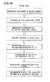
- Fig. 14 is a process flow chart starting with the generation of hydrogen gas to inflammation.
- a unit cell la of a polyelectrolytic fuel cell 1 comprises an anode 3 comprising a reaction catalysis layer 3a and a gas dispersion layer 3b on the left side of an electrolytic film 2 and a cathode 4 comprising a reaction catalysis layer 4a and a gas dispersion layer 4b on the right side of said film 2.
- a carbon current collector 5 concurrently serving as a gas separator is provided, and on the side of this carbon current collector 5 opposite to said gas dispersion layer 3b, a plurality of parallel fuel gas passages 5a are formed and in each fuel gas passage 5a a fuel gas, i.e. hydrogen gas circulates.
- a carbon current collector 6 concurrently serving as a gas separator is provided, and on the side of this carbon current collector 6 opposite to said gas dispersion layer 4b, a plurality of parallel oxidizing gas passages 6a (in the drawing only the forefront passage 6a is illustrated) are formed.
- hydrogen gas (H 2 ) flowing in the fuel gas passage 5a forms protons (2H + ) and electrons (2e - ).
- Protons moves through the electrolytic film 2 which is an ion exchange film towards the cathode 4, and electrons passes through an external circuit (not illustrated) from a carbon current collector 5 on the anode 3 side to move towards a carbon current collector 6 on the cathode side 4.
- water W thus formed in the oxidizing gas passage 6a in each unit cell la of the layer-built fuel cell flows down under the pull of gravity and is discharged outside together with excess oxidizing gas from the discharge manifold 7 connected with the lower end of the oxidizing gas passage 6a of each unit cell la of the layer-built fuel cell.
- the inflammation of hydrogen gas in the passage of reaction gas in the fuel cell 1 raises the pressure in the passage and variations in the supply of reaction gas and other factors could result in an instability of voltage generated.
- heat and rising pressure resulting from inflammation could cause variations in voltage generated and produce adverse effects on the seals and other parts of unit cells la of the fuel cell stack.
- Japanese Patent Application Laid Open No. 4-167236 describes fuel cell equipment comprising cell stacks, a reaction gas pipe line designed to supply and evacuate reaction gas thereto and therefrom, a cell housing and an ambient gas system.
- cell stacks are housed in a cell housing filled with ambient gas
- a reaction gas pipe line is connected to these cell stacks
- an ambient gas system is connected to said cell housing.
- reaction gas combustion gas (combustible component) having leaked from said cell stacks and mixed in ambient gas is removed by burning the same in the cell housing before it is discharged with ambient gas.
- the art described in this patent application laid open does not enable to remove for example fuel gas that has mixed in the oxidizing gas passage within a fuel cell.
- Object of this invention is to prevent any explosive combustion of fuel gas within a polyelectrolytic fuel cell.
- An advantage of this invention is to prevent any possible drop in the output voltage of polyelectrolytic fuel cells due to flooding.
- a further advantage of this invention is to suppress any increase in the concentration of fuel gas contained in oxidizing gas in a polyelectrolytic fuel cell in order to prevent any possible inflammation of said fuel gas.
- a further advantage of this invention is to stabilize the output voltage of polyelectrolytic cells.
- the polyelectrolytic cell of this invention is provided with means to change the conditions of supplying oxidizing gas when at least any one of the following factors has deviated from the tolerance: the output voltage and the internal resistance of a plurality of stacked cells or the humidity of oxidizing gas being discharged. Specifically, when the output voltage has decreased, when the internal resistance has increased or when the humidity of discharge gas has increased, the flow rate of oxidizing gas is increased, or its pressure is increased or the humidity of oxidizing gas is reduced. As a result, the water contents in the cell is removed preventing flooding and any drops in the output voltage resulting therefrom. Further, the generation of hydrogen gas is suppressed in the passages of oxidizing gas.
- this invention uses a chamber leading to the passages for oxidizing gas and an igniter designed to ignite the combustible gas contained therein to burn the same.
- an igniter designed to ignite the combustible gas contained therein to burn the same.
- the polyelectrolytic fuel cell of this invention is provided with a combustion catalysis positioned somewhere in the passage of oxidizing gas, fuel gas mixed in oxidizing gas is oxidized by the catalysis, and as a result the concentration of fuel gas in oxidizing gas is kept at a low level.
- Fig. 1 is a schematic drawing of an example of fuel cell according to this invention.
- Fig. 2 is a block diagram showing the general configuration of the system using this fuel cell.
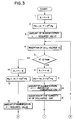
- Fig. 3 is a chart showing a part of a flow chart describing a control routine executed in the system described above.
- Fig. 4 is a chart showing another part of the flow chart mentioned above.
- Fig. 5 is a diagram showing the voltage behavior of a fuel cell system operated consecutively by the control system mentioned above.
- Fig. 6 is a diagram showing the result of performance tests with variable current carried out to study the point of sharp increase of hydrogen gas generated as a result of flooding.
- Fig. 7 is a diagram showing the result of continuous tests with fixed current carried out to study the point of sharp increase of hydrogen gas generated as a result of flooding.
- Fig. 8 is a top sectional view showing a part (unit cell) of fuel cell of another embodiment of this invention.
- Fig. 9 is a cross sectional view showing said fuel cell.
- Fig. 10 is a top sectional view showing a still another embodiment of this invention.
- Fig. 11 is a cross sectional view showing the fuel cell of Fig. 10.
- Fig. 12 is a drawing illustrating the mechanism of mixing of hydrogen gas in the oxygen electrode ofa conventional fuel cell.
- Fig. 13 is a cross sectional view of a conventional fuel cell illustrating the position of stagnation and inflammation of hydrogen gas in the fuel cell.
- Fig. 14 is a flow chart showing the process starting with the generation to inflammation of hydrogen gas in a conventional fuel cell.
- the fuel cell stack 11 comprises a plurality of unit cells 11a standing upright and stacked horizontally.
- Each unit cell 11a comprises a polyelectrolytic film 12 with a fuel electrode formed on one side (on the left-hand side in Fig. 1) and an oxygen electrode formed on the other side and a carbon current collector 15 serving concurrently as a gas separator with fuel gas passages 13 formed horizontally on one side and oxidizing gas passages 14 formed vertically on the other hand, a plurality of fuel gas passages 13 and oxidizing gas passages 14 being formed with a depth and width of approximately 1mm at intervals of approximately 1mm.
- a plurality of unit cells 11a are stacked by sandwiching polyelectrolytic films 12 between these fuel gas passages 13 and oxidizing gas passages 14.
- An end of the fuel gas passage 13 formed in a stack of unit cells 11a is connected with the supply manifold for fuel gas (not illustrated), and the other end is connected with the discharge manifold for fuel gas (not illustrated).
- the top end of the oxidizing gas passage 14 of each unit cell 11a is connected with the supply manifold 16 for oxidizing gas and the bottom end is connected with the discharge manifold 17 for oxidizing gas.
- the whole system is constructed in such a way as to assure that oxygen gas contained in air supplied as oxidizing gas to the oxidizing gas passages 14 through the oxidizing gas manifold 16 and hydrogen gas supplied as fuel gas to the fuel gas passages 13 through the discharge manifold for fuel gas start an elecrochemical process of oxidizing reaction through the polyelectrolytic film 12.
- a fluoric cation exchange film 130 ⁇ m thick on the surface of which electrodes are formed by hot pressing is used.
- the electrodes are made of a basic material of carbon cloth (0.3 mm thick) on the surface of which a catalysis reaction layer and a gas dispersion layer are coated. These electrodes are hot pressed on the surface of the fluoric cation exchange film mentioned above under the conditions of 120°C x 980.7 x 10 4 Pa (Pascal).
- the catalysis reaction layer is made of a material obtained by mixing Pt 20% carrier carbon 0.4mg/cm 2 and a cation exchange resin in such a manner that the ratio of the carrier carbon may account for 50%, while the gas dispersion layer is made from a material based on carbon comprising 50% tetrafluoroethylene treated with this tetrafluoroethylene for water repellent.
- the supply manifold 16 for oxidizing gas mentioned above is formed on a slope of the ceiling rising in the center, and at the peak center a chamber 18 is formed.
- hydrogen gas in the oxidizing gas passages is automatically collected in this chamber 18, and an igniter 19 designed to ignite hydrogen gas so collected is provided in the chamber 18.
- an igniter 19 designed to ignite hydrogen gas so collected is provided in the chamber 18.
- a model that ignites hydrogen gas with spark discharge is adopted.
- water vapor is mixed respectively in hydrogen gas supplied through the fuel gas passages 13 and air supplied through the oxidizing gas passages 14 to keep the polyelectrolytic film 12 moist.
- hydrogen gas (H 2 ) flowing through the fuel gas passages 13 is ionized into protons (H + ) and electrons (e ).
- Ionized protons move through a polyelectrolytic film 12 which is an ion exchange film towards the oxygen electrode, and electrons move from the carbon current collector 15 on the fuel electrode side to the carbon current collector 15 on the oxygen electrode side by passing through an external circuit (not illustrated).
- protons having moved through the polyelectrolytic film 12 from the fuel electrode, and electrons having moved through external circuits react each other to form water (H 2 0).
- Fig. 2 The general configuration of the fuel cell generation system incorporating the fuel cell stack 11 mentioned above is illustrated in Fig. 2 in the form of a block diagram.
- a load L is connected through a relay contact 20, and at the same time a computer control device 23 designed to control the operation of the fuel cell is connected in parallel with the load L mentioned above.
- an end of an oxidizing gas supply pipe line 25 the other end of which is connected to an air supplier 27 is connected.
- an end of the fuel gas supply pipe line 26 the other end of which is connected with a hydrogen gas supplier 28 is connected.
- a fuel gas discharge pipe line 34 connected with the discharge side of the discharge manifold for fuel gas not illustrated and a oxidizing gas discharge pipe line 35 connected with the discharge side of the discharge manifold 17 for oxidizing gas are provided.
- thermometers/hygrometers 36 and 36a, condensers 37 and 37a and pressure regulating valves 38 and 38a are provided in the order indicated from the manifold side.
- thermometers/hygrometers 33 and 33a provided respectively on the oxidizing gas supply pipe line 25 and the fuel gas supply pipe line 26 and the thermometers/hygrometers 36 and 36a respectively provided on the oxidizing gas discharge pipe line 34 and the fuel gas discharge pipe line 35 at the respective positions are constantly inputted in the computer control device.
- the computer control device 23 sends signals to the humidifiers 31 and 31a and other equipment on the oxidizing gas supply pipe line 25 and the fuel gas supply pipe line 26 and the pressure regulating valves 38 and 38a and other equipment on the oxidizing gas discharge pipe line 34 and the fuel gas discharge pipe line 35 to control any drops in output voltage and any possible development of flooding.
- FIGs. 3 and 4 are a flow chart illustrating an example thereof. These charts are two sections of a flow chart, divided for the convenience of drawing, and encircled figures show that the lines of the same figures are linked.
- the amount of air supply A is set such that the ratio of air to fuel gas (A/F ratio) will be 4, and at Step 2, the air pressure PA is set at 14.7 x 10 4 Pa. And at Step 3, the amount of humidification is set at a predetermined value. This is due to the use of air as the oxidizing gas requiring a compensation of a low partial pressure of oxygen in the air.
- Step 9 the humidity of the discharge gas shown by the thermometer/hygrometer 36 at the outlet of the discharge manifold for oxidizing gas is inserted.
- Step 10 the current I and voltage V outputted from the fuel cell stack 11 are inserted, and at Step 11 the value of internal resistance ZIN, or [a.c. voltage e/a.c. current i] is sought. And at Step 12, the humidity of discharge gas M and its reference value MO are compared and the internal resistance ZIN and its reference value ZO are also compared.
- Step 14 the ratio of air-fuel gas is maintained at "4", and at Step 15 the pressure of air supply PA is maintained at 14.7 x 10 Pa. Then at Step 16 the amount of humidification is maintained at the predetermined value and then one proceeds to Step 17.
- Step 12 as the result of comparisons of the humidity of the discharge gas M and the internal resistance ZIN with their respective reference values MO and ZO, if M > MO or ZIN > ZO, the amount of humidification is considered adequate, and then follows Step 17.
- the computer control device 23 sends signals to the mass flow controllers 30 and 30a to control the amount of air supplied so that the latter may be equal to a newly set value.
- signals are sent to the pressure regulating valves 29 and 38a to control the pressure of air supply so that the latter may be equal to a newly set value.
- signals are sent to the humidifier 31 to regulate the ratio of oxidizing gas having passed through the humidifier 31 to that having passed through a bypass pipe 31b so that the amount of humidification may be equal to a newly set value.
- Step 20 the output voltage VC and the limit of operation voltage V limit are compared, and if the output voltage is greater (VC > Vlimit), the whole system is considered as being operated adequately, and then returns to Step 4 where the control steps described above are repeated.
- the computer control device 23 ignites the igniter 19 (Step 23) to generate a spark in the chamber 18 of the supply manifold 16 for oxidizing gas burning hydrogen gas collected in this chamber 18.
- a drop in the output voltage VC to a level below the reference voltage Vmin leads to changes in the amount of air supplied, pressure and humidity of air serving as the oxidizing gas preventing any further drops in the output voltage.
- an increase in the amount of air supplied accelerates the dispersion of oxygen on the surface of electrodes enhancing the reaction of oxygen with hydrogen and thus increasing the generating capacity of the fuel cell.
- An increase in moisture content carried away by air serves to reduce excessive moisture on the surface of electrodes, which accelerate the reaction of hydrogen with oxygen and therefore increase the generating capacity of the cell.
- a higher pressure of air raises the partial pressure of oxygen on the surface of electrodes accelerating likewise the dispersion of oxygen on the surface of electrodes, and the resulting increase in the reaction of oxygen with hydrogen increases the generating capacity of the fuel cell.
- Fig. 5 is a diagram showing the behavior of voltage when the fuel cell stack 11 is continuously operated to generate electricity at a current density of 0.7A/cm 2 by means of operation control of a programmed computer control device 23.
- the operation control method of this embodiment as described above detects any flooding at the initial stage of development and enables to take appropriate measures to dissolve such flooding. Therefore, it improves the stability of voltage during the operation of the fuel cell and enables to prevent any sudden increase of hydrogen gas and therefore enables to prevent the deterioration of the performance of unit cells due to the heat and rising pressure resulting from the intense combustion of hydrogen gas in the fuel cell.
- the minimum normal voltage Vmin of 0.4V and the limit of operation voltage Vlimit of approximately 0.12V were set for the following reasons.
- the supply of oxygen to the oxygen electrodes is impeded and so-called flooding occurs.
- the effect will be limited to decreased supply of oxygen to the oxygen electrodes and some decreased in the output voltage.
- the gas dispersion layer is completely covered with water and the reaction catalysis layer of the oxygen electrodes is almost completely cut off from the supply of oxygen. Therefore, protons having moved to the oxygen electrodes recombine with electrons to form hydrogen gas. It was found that the amount of hydrogen gas thus formed suddenly increases when the state of flooding progressed to a certain stage and when output voltage has decreased.
- flow rate or pressure may be separately controlled or either one of these and humidity may be controlled together.
- the fuel cell 40 comprises a plurality of unit cells 41 respectively standing vertically and stacked horizontally, each unit cell 41 comprising a polyelectrolytic film 42 on one side of which (on the upper side in Fig. 8) an anode (fuel electrode) 45 comprising a catalysis reaction layer 43 and a gas dispersion layer 44 on its outside are formed, and on the outside of this anode 45 a carbon current collector 46 serving concurrently as a gas separator made of a gasproof plate is provided in close contact.
- each unit cell 41 comprising a polyelectrolytic film 42 on one side of which (on the upper side in Fig. 8) an anode (fuel electrode) 45 comprising a catalysis reaction layer 43 and a gas dispersion layer 44 on its outside are formed, and on the outside of this anode 45 a carbon current collector 46 serving concurrently as a gas separator made of a gasproof plate is provided in close contact.
- a plurality of passages for fuel gas 47 in which hydrogen gas (H 2 ) serving as fuel gas flows are formed with a depth of lmm, width of lmm and at intervals of lmm.
- a cathode (oxygen electrode) 50 comprising a catalysis reaction layer 48 and a gas dispersion layer 49 on its outside is formed.
- a carbon current collector 46 serving concurrently as a gas separator and formed in the form of a plate is provided in close contact.
- a plurality of oxidizing gas passages 52 in which air serving as oxidizing gas flows in a direction orthogonal to the direction of formation of the fuel gas passages 47 mentioned above are formed to constitute a unit cell 41.
- this unit cell 41 is stacked horizontally in a plurality of layers so that the oxidizing gas passages 52 mentioned above may be vertical, and the top end of the oxidizing gas passage 52 in each stacked unit cell 41 is each connected with the oxidizing gas supply side manifold 53 while the bottom end of each oxidizing gas passage 52 is each connected with the discharge side manifold 54.
- the upstream side and the downstream side of each fuel gas passage 47 are, although not illustrated, connected with the supply side manifold and the discharge side manifold of fuel gas.
- polyelectrolytic film 42 described above is formed in a similar way to the polyelectrolytic film 42 of the embodiment illustrated in Figs. 1 and 2.
- each oxidizing gas passage 52 formed in the carbon current collector 46 are coated or impregnated with Pt catalysis carrier liquid (for example, dinitrodiamine platinum, hexaammine platinum chloride, platinic chloride acid six hydrates) for carrier treatment to form a combustion catalysis layer 55.
- Pt catalysis carrier liquid for example, dinitrodiamine platinum, hexaammine platinum chloride, platinic chloride acid six hydrates
- the fuel gas passage 47 on the anode 45 side is supplied with hydrogen gas (H 2 ).
- the polyelectrolytic film 42 is hydrated to saturation to serve as a proton conductive electrolyte with relative resistance equal to or less than 20 ⁇ ⁇ cm at normal temperature, and for this purpose hydrogen gas supplied through the fuel gas passage 47 and air supplied through the oxidizing gas passage 52 are mixed with vapor to keep the polyelectrolyte 42 moist.
- hydrogen gas (H 2 ) flowing through the fuel gas passage 47 forms protons (2H + ) and electrons (2e).
- Protons move through the polyelectrolytic film 42 which is an ion exchange film towards the cathode 50, and electrons move from the carbon current collector 46 on the anode 45 side through an external circuit (not shown) to the carbon current collector 46 on the cathode 50 side.
- Fig. 10 illustrates another embodiment in which a fuel catalysis layer is provided.
- a combustion catalysis layer was formed inside the oxidizing gas passage.
- a combustion catalysis layer is formed on the surface of the cathode facing the oxidizing gas passage.
- unit cells 61 forming part of the fuel cell has an anode 45 comprising a catalysis reaction layer 43 and a gas dispersion layer 44 on one side (upper side in Fig. 10) of its polyelectrolytic film 42, and on the outside of this anode 45 a carbon current collector 46 is provided in close contact thereto. Furthermore, on the side of this carbon current collector 46 facing the anode 45, fuel gas passages are provided. On the other side of the previously described polyelectrolytic film 42, a cathode 50 is formed comprising a catalysis reaction layer 48 and a gas dispersion layer 49. On the outer surface of this cathode 50, a combustion catalysis layer 77 is provided. Further, on the outside of this cathode 50, a carbon current collector 46 is provided and on the side of this carbon current collector 46 facing the cathode 50, oxidizing gas passages 52 are formed.
- the combustion catalysis layer previously described 77 is formed by coating a water repellent agent containing tetrafluoroethylene on the surface of carbon carrying H 3 Pt(SO 3 ) 2 OHsol made from hexahydroxine platinic acid by the carbon black colloid dispersion method (Plototech method).
- the horizontal stacking of unit cells 61 formed as described above in such a way that the oxidizing gas passages 52 may be formed vertically as they were in the embodiment previously described and the connection of manifolds to each of gas passages to form the fuel cell and the operation of the same as it was in the embodiment previously described provide the required generating capacity.
- Fig. 11 shows another embodiment of fuel cell related to this invention.
- the combustion catalysis layer was formed by coating or impregnating the inside of the oxidizing gas passage or on the surface of the cathode, while in this embodiment pellets carrying combustion catalyses are provided in the oxidizing gas passages. It should be noted further that the components identical to those used in the embodiment mentioned above are marked with identical reference numerals and any detailed descriptions thereon are omitted.
- a plurality of unit cells 81 forming part of the fuel cell 80 have anodes (not shown) comprising a polyelectrolytic film 42 with a catalysis reaction layer and a gas dispersion layer on one side thereof.
- anodes comprising a polyelectrolytic film 42 with a catalysis reaction layer and a gas dispersion layer on one side thereof.
- a carbon current collector 46 is provided in close contact and on the surface of this carbon current collector 46 facing the anode mentioned above fuel gas passages 47 are formed.
- a cathode (not shown) comprising a catalysis reaction layer and a gas dispersion layer is provide.
- a carbon current collector 46 is provided, and on the surface of this carbon current collector 46 facing the cathode 50 oxidizing gas passages 52 are formed.
- the unit cells 81 formed as described above are stacked horizontally in such a way that their oxidizing gas passages 52 may be vertical, and the upstream side of the oxidizing gas passages (the top side in Fig. 11) is connected to the oxidizing gas supply side manifold 53 and the downstream side (the bottom side in Fig. 11) is connected to the oxidizing gas supply side manifold 53. And the upstream and downstream sides of the fuel gas passages 47 mentioned above and not shown are respectively connected with the supply side manifold and the discharge side manifold.
- catalysis carrier pellets 87 (dimension: several mm square or less) made on the basis of a porous carrier (alumina, carbon, etc.) containing platinum or other catalyses are scattered in the supply side manifold 53 in such a way that they do not impede the flow of oxidizing gas.
- H 2 moves upward in the oxidizing gas passages 52 and gathers in the supply side manifold 53, and upon coming in contact with the combustion catalysis layer 77 formed facing the oxidizing gas passage 52, H 2 instantly oxidizes. Thus it was confirmed that the mixing of a large amount of H 2 in oxidizing gas can be prevented.
- the gas when fuel gas has started to spring up suddenly, the gas is caught in a chamber and ignited by means of a igniter. In this way, the combustion of fuel gas in the fuel cell and any resulting damages to the cell can be prevented.
- the fuel cell of this invention is characterized in that hydrogen gas having mixed in oxidizing gas, upon coming in contact with the combustion catalysis layer formed in the reaction gas passage, is burnt mildly at an early stage.
- hydrogen gas having mixed in oxidizing gas upon coming in contact with the combustion catalysis layer formed in the reaction gas passage, is burnt mildly at an early stage.
- combustion catalyses mounted in either one of the reaction gas supply side manifold and the reaction gas discharge side manifold connected with the reaction gas passages enable to burn mildly and at an early stage hydrogen gas stagnating in the manifold and restrict any increases in the concentration of hydrogen gas having mixed.
Applications Claiming Priority (5)
| Application Number | Priority Date | Filing Date | Title |
|---|---|---|---|
| JP6302948A JPH08138697A (ja) | 1994-11-11 | 1994-11-11 | 燃料電池 |
| JP302948/94 | 1994-11-11 | ||
| JP332072/94 | 1994-12-12 | ||
| JP33207294A JP3584511B2 (ja) | 1994-12-12 | 1994-12-12 | 高分子電解質型燃料電池の運転制御方法 |
| EP95117605A EP0716463B9 (de) | 1994-11-11 | 1995-11-08 | Polyelektrolytische Brennstoffzelle und Verfahren zur Betriebssteuerung |
Related Parent Applications (1)
| Application Number | Title | Priority Date | Filing Date |
|---|---|---|---|
| EP95117605.6 Division | 1995-11-08 |
Publications (1)
| Publication Number | Publication Date |
|---|---|
| EP0911899A2 true EP0911899A2 (de) | 1999-04-28 |
Family
ID=26563326
Family Applications (2)
| Application Number | Title | Priority Date | Filing Date |
|---|---|---|---|
| EP95117605A Expired - Lifetime EP0716463B9 (de) | 1994-11-11 | 1995-11-08 | Polyelektrolytische Brennstoffzelle und Verfahren zur Betriebssteuerung |
| EP98117266A Withdrawn EP0911899A2 (de) | 1994-11-11 | 1995-11-08 | Polyelektrolytische Brennstoffzelle mit Verbrennungskatalysator in den Durchflüssen des oxydierenden Gases |
Family Applications Before (1)
| Application Number | Title | Priority Date | Filing Date |
|---|---|---|---|
| EP95117605A Expired - Lifetime EP0716463B9 (de) | 1994-11-11 | 1995-11-08 | Polyelektrolytische Brennstoffzelle und Verfahren zur Betriebssteuerung |
Country Status (4)
| Country | Link |
|---|---|
| US (1) | US5939218A (de) |
| EP (2) | EP0716463B9 (de) |
| KR (1) | KR0171207B1 (de) |
| DE (1) | DE69533215T2 (de) |
Cited By (4)
| Publication number | Priority date | Publication date | Assignee | Title |
|---|---|---|---|---|
| US6383676B1 (en) * | 1999-03-01 | 2002-05-07 | Sanyo Electric Co., Ltd. | Polymer electrolyte fuel cell device |
| EP1298751A2 (de) * | 2001-09-27 | 2003-04-02 | Matsushita Electric Industrial Co., Ltd. | Polymer-Electrolyt-Brennstoffzelle und ihr Herstellugsverfahren |
| WO2005053070A1 (en) * | 2003-11-04 | 2005-06-09 | Toyota Jidosha Kabushiki Kaisha | Fuel cell system |
| DE102006022863B4 (de) * | 2005-05-17 | 2010-09-02 | GM Global Technology Operations, Inc., Detroit | Verfahren zum Betreiben eines Brennstoffzellensystems |
Families Citing this family (48)
| Publication number | Priority date | Publication date | Assignee | Title |
|---|---|---|---|---|
| US6444343B1 (en) | 1996-11-18 | 2002-09-03 | University Of Southern California | Polymer electrolyte membranes for use in fuel cells |
| DE19649436C1 (de) * | 1996-11-28 | 1998-01-15 | Siemens Ag | Verfahren zum Erkennen eines Gaslecks |
| EP0867963A3 (de) * | 1997-03-25 | 2002-09-04 | Matsushita Electric Industrial Co., Ltd. | Polymerelektrolytbrennstoffzelle |
| US5935726A (en) * | 1997-12-01 | 1999-08-10 | Ballard Power Systems Inc. | Method and apparatus for distributing water to an ion-exchange membrane in a fuel cell |
| KR100446605B1 (ko) * | 1998-02-27 | 2004-11-08 | 삼성전자주식회사 | 수소이온교환막연료전지의활성화방법 |
| US6187464B1 (en) * | 1998-06-01 | 2001-02-13 | Matsushita Electric Industrial Co., Ltd. | Method for activating fuel cell |
| KR100389447B1 (ko) * | 1998-06-10 | 2003-10-10 | 현대중공업 주식회사 | 고분자전해질연료전지의가습과활성화운전을통한초기화운전방법 |
| US6638652B1 (en) * | 1998-10-02 | 2003-10-28 | Toyota Jidosha Kabushiki Kaisha | Fuel cell control apparatus |
| JP4200576B2 (ja) * | 1999-02-23 | 2008-12-24 | トヨタ自動車株式会社 | 燃料電池システム |
| US6380126B1 (en) | 1999-08-20 | 2002-04-30 | Medis El Ltd | Class of electrocatalysts and a gas diffusion electrode based thereon for fuel cells |
| US6936370B1 (en) | 1999-08-23 | 2005-08-30 | Ballard Power Systems Inc. | Solid polymer fuel cell with improved voltage reversal tolerance |
| US6517962B1 (en) | 1999-08-23 | 2003-02-11 | Ballard Power Systems Inc. | Fuel cell anode structures for voltage reversal tolerance |
| WO2001028022A1 (en) * | 1999-10-14 | 2001-04-19 | Motorola Inc. | Method and apparatus for managing hydration level of fuel cell electrolyte |
| JP4686814B2 (ja) * | 1999-11-17 | 2011-05-25 | 株式会社エクォス・リサーチ | 燃料電池装置 |
| US6686078B1 (en) | 2000-09-29 | 2004-02-03 | Plug Power Inc. | Method of reformer operation to prevent fuel cell flooding |
| US6953635B2 (en) | 2000-10-04 | 2005-10-11 | Honda Giken Kogyo Kabushiki Kaisha | Humidifier for fuel cell |
| JP5017760B2 (ja) | 2000-11-28 | 2012-09-05 | トヨタ自動車株式会社 | 燃料電池の出力特性推定装置および出力特性推定方法、燃料電池システムおよびこれを搭載する車両、燃料電池出力制御方法並びに記憶媒体 |
| KR100763143B1 (ko) * | 2000-12-29 | 2007-10-05 | 주식회사 엘지이아이 | 연료전지의 출력저하방지장치 |
| US6878664B1 (en) | 2001-01-16 | 2005-04-12 | Medis El Ltd. | Class of electrocatalysts and a gas diffusion electrode based thereon for fuel cells |
| US7141326B2 (en) * | 2001-04-06 | 2006-11-28 | Honda Giken Kogyo Kabushiki Kaisha | Warm-up apparatus for fuel cell |
| US6635370B2 (en) * | 2001-06-01 | 2003-10-21 | Utc Fuel Cells, Llc | Shut-down procedure for hydrogen-air fuel cell system |
| US20030022036A1 (en) * | 2001-07-25 | 2003-01-30 | Ballard Power Systems Inc. | Fuel cell controller self inspection |
| US6979504B2 (en) * | 2001-07-25 | 2005-12-27 | Ballard Power Systems Inc. | Fuel cell system automatic power switching method and apparatus |
| US6953630B2 (en) * | 2001-07-25 | 2005-10-11 | Ballard Power Systems Inc. | Fuel cell anomaly detection method and apparatus |
| US6861167B2 (en) * | 2001-07-25 | 2005-03-01 | Ballard Power Systems Inc. | Fuel cell resuscitation method and apparatus |
| JP4250877B2 (ja) | 2001-08-07 | 2009-04-08 | ソニー株式会社 | 電源装置 |
| US6686084B2 (en) | 2002-01-04 | 2004-02-03 | Hybrid Power Generation Systems, Llc | Gas block mechanism for water removal in fuel cells |
| US7222001B2 (en) * | 2002-05-14 | 2007-05-22 | Plug Power Inc. | System for monitoring and controlling fuel cell-based power generation units |
| KR20040000574A (ko) * | 2002-06-21 | 2004-01-07 | 엘지전자 주식회사 | 연료전지의 성능조절장치 |
| WO2004049487A2 (en) * | 2002-11-27 | 2004-06-10 | Hydrogenics Corporation | Method of operating a fuel cell power system to deliver constant power |
| JP4273781B2 (ja) * | 2003-02-05 | 2009-06-03 | トヨタ自動車株式会社 | 燃料電池の運転状態判定装置及びその方法 |
| JP2006526271A (ja) * | 2003-05-15 | 2006-11-16 | 日産自動車株式会社 | 燃料電池システム |
| JP4806886B2 (ja) | 2003-05-16 | 2011-11-02 | トヨタ自動車株式会社 | 燃料電池システムの運転制御 |
| JP4730643B2 (ja) * | 2003-11-07 | 2011-07-20 | トヨタ自動車株式会社 | ガス処理装置 |
| US7781118B2 (en) * | 2004-02-09 | 2010-08-24 | Gm Global Technology Operations, Inc. | Fuel cell flooding detection |
| DE502004008081D1 (de) * | 2004-03-04 | 2008-10-30 | Siemens Ag | Brennstoffzellenanlage und Verfahren zum Betrieb derselben |
| JP2006086006A (ja) * | 2004-09-16 | 2006-03-30 | Toyota Motor Corp | 燃料電池システム |
| JP2007207442A (ja) * | 2006-01-30 | 2007-08-16 | Toyota Motor Corp | 燃料電池システム |
| US20070275275A1 (en) * | 2006-05-23 | 2007-11-29 | Mesa Scharf | Fuel cell anode purge systems and methods |
| JP5136415B2 (ja) * | 2006-07-14 | 2013-02-06 | トヨタ自動車株式会社 | 燃料電池システム |
| US7608358B2 (en) | 2006-08-25 | 2009-10-27 | Bdf Ip Holdings Ltd. | Fuel cell anode structure for voltage reversal tolerance |
| JP5013311B2 (ja) * | 2006-11-22 | 2012-08-29 | トヨタ自動車株式会社 | 燃料電池システム |
| JP2009016155A (ja) * | 2007-07-04 | 2009-01-22 | Toyota Motor Corp | 燃料電池の制御装置および燃料電池システム |
| JP5407132B2 (ja) * | 2007-10-15 | 2014-02-05 | 日産自動車株式会社 | 燃料電池システムの起動制御装置及び起動制御方法 |
| US8574731B2 (en) * | 2008-10-29 | 2013-11-05 | Motorola Mobility Llc | Device and method for augmenting the useful life of an energy storage device |
| JP4730456B2 (ja) * | 2009-05-25 | 2011-07-20 | トヨタ自動車株式会社 | 燃料電池搭載車両 |
| CA3001100C (en) * | 2015-10-05 | 2022-03-01 | Nissan Motor Co., Ltd. | Fuel cell state determination method and fuel cell state determination apparatus |
| DE102017212846A1 (de) * | 2017-07-26 | 2019-01-31 | Robert Bosch Gmbh | Verteilerstruktur zum Bereitstellen mindestens eines Reaktionsgases |
Family Cites Families (32)
| Publication number | Priority date | Publication date | Assignee | Title |
|---|---|---|---|---|
| US3268364A (en) * | 1962-01-29 | 1966-08-23 | Honeywell Inc | Fuel cell control system |
| US3432356A (en) * | 1963-09-11 | 1969-03-11 | Gen Electric | Regulated fuel cell system |
| US3343991A (en) * | 1966-02-16 | 1967-09-26 | Allis Chalmers Mfg Co | Control for a system with a parabolic relationship between a parameter and an output |
| FR1547910A (fr) * | 1967-12-06 | 1968-11-29 | Bbc Brown Boveri & Cie | Procédé et dispositif pour l'évacuation de l'eau de réaction hors de piles à combustible |
| US3753780A (en) * | 1971-09-30 | 1973-08-21 | Us Army | Fluctuation sensitive fuel cell replenishment control means |
| JPS54144934A (en) | 1978-05-02 | 1979-11-12 | Fuji Electric Co Ltd | Fuel battery |
| JPS5834574A (ja) * | 1981-08-21 | 1983-03-01 | Hitachi Ltd | 燃料電池 |
| JPS5887770A (ja) * | 1981-11-18 | 1983-05-25 | Toshiba Corp | 燃料電池の極間差圧制御装置 |
| JPS5894767A (ja) * | 1981-11-30 | 1983-06-06 | Toshiba Corp | 燃料電池装置 |
| US4722873A (en) * | 1985-12-06 | 1988-02-02 | Mitsubishi Denki Kabushiki Kaisha | Fuel cell power generating system |
| JPS62176064A (ja) * | 1986-01-28 | 1987-08-01 | Hitachi Ltd | メタノ−ル燃料電池 |
| JPS63236262A (ja) * | 1987-03-25 | 1988-10-03 | Hitachi Ltd | 燃料電池 |
| US4755439A (en) * | 1987-03-25 | 1988-07-05 | International Fuel Cells Corporation | Fuel cell configuration for contaminated fuel gases and method of using the same |
| US4729930A (en) * | 1987-05-29 | 1988-03-08 | International Fuel Cells Corporation | Augmented air supply for fuel cell power plant during transient load increases |
| US4826741A (en) * | 1987-06-02 | 1989-05-02 | Ergenics Power Systems, Inc. | Ion exchange fuel cell assembly with improved water and thermal management |
| US4904548A (en) * | 1987-08-03 | 1990-02-27 | Fuji Electric Co., Ltd. | Method for controlling a fuel cell |
| US4859545A (en) * | 1988-05-05 | 1989-08-22 | International Fuel Cells Corporation | Cathode flow control for fuel cell power plant |
| US4943493A (en) * | 1989-04-21 | 1990-07-24 | International Fuel Cells Corporation | Fuel cell power plant |
| DE3929730A1 (de) * | 1989-09-07 | 1991-03-21 | Kernforschungsz Karlsruhe | Wasserstoff/sauerstoff-brennstoffzelle |
| US5290641A (en) * | 1989-10-06 | 1994-03-01 | Fuji Electric Co., Ltd. | Method of controlling operation of fuel cell power supply |
| JPH0766825B2 (ja) * | 1990-10-30 | 1995-07-19 | 株式会社日立製作所 | 燃料電池雰囲気ガス処理装置 |
| JPH04167236A (ja) | 1990-10-31 | 1992-06-15 | Toshiba Corp | 光ディスク装置 |
| US5260143A (en) * | 1991-01-15 | 1993-11-09 | Ballard Power Systems Inc. | Method and apparatus for removing water from electrochemical fuel cells |
| JPH05251097A (ja) | 1992-03-03 | 1993-09-28 | Fuji Electric Co Ltd | 固体高分子電解質型燃料電池 |
| JPH05251098A (ja) * | 1992-03-05 | 1993-09-28 | Toshiba Corp | 燃料電池の保持電解質管理方法 |
| US5366821A (en) * | 1992-03-13 | 1994-11-22 | Ballard Power Systems Inc. | Constant voltage fuel cell with improved reactant supply and control system |
| JPH0668886A (ja) * | 1992-08-19 | 1994-03-11 | Fuji Electric Co Ltd | 固体高分子電解質型燃料電池のセル構造 |
| JPH0689730A (ja) * | 1992-09-10 | 1994-03-29 | Fuji Electric Co Ltd | 固体高分子電解質型燃料電池 |
| JP3271801B2 (ja) * | 1992-09-22 | 2002-04-08 | 田中貴金属工業株式会社 | 高分子固体電解質型燃料電池、該燃料電池の加湿方法、及び製造方法 |
| EP0596367A1 (de) * | 1992-11-05 | 1994-05-11 | Siemens Aktiengesellschaft | Brennstoffzellenblock und Verfahren zur Einstellung der Inertgasabfuhr aus dem Brennstoffzellenblock |
| EP0596366B1 (de) * | 1992-11-05 | 1997-04-23 | Siemens Aktiengesellschaft | Verfahren und Einrichtung zur Wasser- und/oder Inertgasentsorgung eines Brennstoffzellenblocks |
| JPH06223850A (ja) * | 1993-01-29 | 1994-08-12 | Mitsubishi Heavy Ind Ltd | 固体高分子電解質燃料電池の運転保護システム |
-
1995
- 1995-11-07 KR KR1019950039999A patent/KR0171207B1/ko not_active IP Right Cessation
- 1995-11-08 EP EP95117605A patent/EP0716463B9/de not_active Expired - Lifetime
- 1995-11-08 DE DE69533215T patent/DE69533215T2/de not_active Expired - Fee Related
- 1995-11-08 EP EP98117266A patent/EP0911899A2/de not_active Withdrawn
- 1995-11-09 US US08/555,404 patent/US5939218A/en not_active Expired - Fee Related
Cited By (6)
| Publication number | Priority date | Publication date | Assignee | Title |
|---|---|---|---|---|
| US6383676B1 (en) * | 1999-03-01 | 2002-05-07 | Sanyo Electric Co., Ltd. | Polymer electrolyte fuel cell device |
| EP1298751A2 (de) * | 2001-09-27 | 2003-04-02 | Matsushita Electric Industrial Co., Ltd. | Polymer-Electrolyt-Brennstoffzelle und ihr Herstellugsverfahren |
| EP1298751A3 (de) * | 2001-09-27 | 2006-04-26 | Matsushita Electric Industrial Co., Ltd. | Polymer-Electrolyt-Brennstoffzelle und ihr Herstellugsverfahren |
| US7132187B2 (en) | 2001-09-27 | 2006-11-07 | Matsushita Electric Industrial Co., Ltd. | Polymer electrolyte fuel cell and production method thereof |
| WO2005053070A1 (en) * | 2003-11-04 | 2005-06-09 | Toyota Jidosha Kabushiki Kaisha | Fuel cell system |
| DE102006022863B4 (de) * | 2005-05-17 | 2010-09-02 | GM Global Technology Operations, Inc., Detroit | Verfahren zum Betreiben eines Brennstoffzellensystems |
Also Published As
| Publication number | Publication date |
|---|---|
| EP0716463A2 (de) | 1996-06-12 |
| DE69533215T2 (de) | 2005-06-30 |
| KR0171207B1 (ko) | 1999-03-30 |
| KR960019839A (ko) | 1996-06-17 |
| EP0716463A3 (de) | 1996-11-13 |
| US5939218A (en) | 1999-08-17 |
| DE69533215D1 (de) | 2004-08-05 |
| EP0716463B9 (de) | 2005-01-05 |
| EP0716463B1 (de) | 2004-06-30 |
Similar Documents
| Publication | Publication Date | Title |
|---|---|---|
| US5939218A (en) | Polyelectrolytic fuel cell and the method of controlling the operation thereof | |
| JP3584511B2 (ja) | 高分子電解質型燃料電池の運転制御方法 | |
| US6376111B1 (en) | System and method for controlling the humidity level of a fuel cell | |
| US20080160363A1 (en) | Control of the Polymer Humidifying Membrane of a Fuel Cell | |
| US7465509B2 (en) | Fuel cell system with degradation protected anode | |
| JP3989604B2 (ja) | 固体電解質燃料電池の起動停止方法 | |
| US20090110972A1 (en) | Fuel cell system | |
| US20070099040A1 (en) | Fuel cell system, method of starting fuel cell system | |
| JP2924009B2 (ja) | 燃料電池の発電停止方法 | |
| JP2006210004A (ja) | 燃料電池システム | |
| US7029775B2 (en) | Fuel cell system | |
| CA2433167C (en) | Fuel cell and method of controlling same | |
| EP1102341A2 (de) | Brennstoffzellenanlage mit Wasserspritzvorrichtung | |
| US20070003805A1 (en) | Fuel cell system and method for stopping operation of fuel cell system | |
| JP2004172125A (ja) | 乾燥したカソード供給による燃料電池システム | |
| JP4126741B2 (ja) | 燃料電池装置の排気方法 | |
| JP2010027443A (ja) | 燃料電池システム | |
| Mu et al. | Numerical study of the gas purging process of a proton exchange membrane fuel cell | |
| JP4617647B2 (ja) | 燃料電池システムとその運転方法 | |
| EP1052717B1 (de) | Brennstoffzellenanlage | |
| BR0314816B1 (pt) | método para limitar o cruzamento de combustìvel em um sistema de célula de combustìvel e sistema de célula de combustìvel para limitar o cruzamento de combustìvel. | |
| JP2019102437A (ja) | 固体酸化物形燃料電池システム | |
| JP2005025996A (ja) | 高分子型燃料電池システムおよびその運転方法 | |
| JPH08138697A (ja) | 燃料電池 | |
| JP2004349067A (ja) | 燃料電池システム |
Legal Events
| Date | Code | Title | Description |
|---|---|---|---|
| PUAI | Public reference made under article 153(3) epc to a published international application that has entered the european phase |
Free format text: ORIGINAL CODE: 0009012 |
|
| 17P | Request for examination filed |
Effective date: 19980911 |
|
| AC | Divisional application: reference to earlier application |
Ref document number: 716463 Country of ref document: EP |
|
| AK | Designated contracting states |
Kind code of ref document: A2 Designated state(s): DE FR GB |
|
| STAA | Information on the status of an ep patent application or granted ep patent |
Free format text: STATUS: THE APPLICATION IS DEEMED TO BE WITHDRAWN |
|
| 18D | Application deemed to be withdrawn |
Effective date: 20030531 |