EP0907535B1 - Installation de freinage hydraulique pourvue d'un dispositif de precharge - Google Patents
Installation de freinage hydraulique pourvue d'un dispositif de precharge Download PDFInfo
- Publication number
- EP0907535B1 EP0907535B1 EP97930387A EP97930387A EP0907535B1 EP 0907535 B1 EP0907535 B1 EP 0907535B1 EP 97930387 A EP97930387 A EP 97930387A EP 97930387 A EP97930387 A EP 97930387A EP 0907535 B1 EP0907535 B1 EP 0907535B1
- Authority
- EP
- European Patent Office
- Prior art keywords
- brake
- valve
- return pump
- brake system
- pressure
- Prior art date
- Legal status (The legal status is an assumption and is not a legal conclusion. Google has not performed a legal analysis and makes no representation as to the accuracy of the status listed.)
- Expired - Lifetime
Links
- 230000006835 compression Effects 0.000 claims description 5
- 238000007906 compression Methods 0.000 claims description 5
- 239000012530 fluid Substances 0.000 claims description 3
- 238000011144 upstream manufacturing Methods 0.000 claims 1
- 238000002955 isolation Methods 0.000 description 4
- 230000000994 depressogenic effect Effects 0.000 description 1
- 230000037452 priming Effects 0.000 description 1
Images

Classifications
-
- B—PERFORMING OPERATIONS; TRANSPORTING
- B60—VEHICLES IN GENERAL
- B60T—VEHICLE BRAKE CONTROL SYSTEMS OR PARTS THEREOF; BRAKE CONTROL SYSTEMS OR PARTS THEREOF, IN GENERAL; ARRANGEMENT OF BRAKING ELEMENTS ON VEHICLES IN GENERAL; PORTABLE DEVICES FOR PREVENTING UNWANTED MOVEMENT OF VEHICLES; VEHICLE MODIFICATIONS TO FACILITATE COOLING OF BRAKES
- B60T8/00—Arrangements for adjusting wheel-braking force to meet varying vehicular or ground-surface conditions, e.g. limiting or varying distribution of braking force
- B60T8/32—Arrangements for adjusting wheel-braking force to meet varying vehicular or ground-surface conditions, e.g. limiting or varying distribution of braking force responsive to a speed condition, e.g. acceleration or deceleration
- B60T8/34—Arrangements for adjusting wheel-braking force to meet varying vehicular or ground-surface conditions, e.g. limiting or varying distribution of braking force responsive to a speed condition, e.g. acceleration or deceleration having a fluid pressure regulator responsive to a speed condition
- B60T8/48—Arrangements for adjusting wheel-braking force to meet varying vehicular or ground-surface conditions, e.g. limiting or varying distribution of braking force responsive to a speed condition, e.g. acceleration or deceleration having a fluid pressure regulator responsive to a speed condition connecting the brake actuator to an alternative or additional source of fluid pressure, e.g. traction control systems
- B60T8/4809—Traction control, stability control, using both the wheel brakes and other automatic braking systems
- B60T8/4827—Traction control, stability control, using both the wheel brakes and other automatic braking systems in hydraulic brake systems
- B60T8/4863—Traction control, stability control, using both the wheel brakes and other automatic braking systems in hydraulic brake systems closed systems
- B60T8/4872—Traction control, stability control, using both the wheel brakes and other automatic braking systems in hydraulic brake systems closed systems pump-back systems
- B60T8/4881—Traction control, stability control, using both the wheel brakes and other automatic braking systems in hydraulic brake systems closed systems pump-back systems having priming means
-
- B—PERFORMING OPERATIONS; TRANSPORTING
- B60—VEHICLES IN GENERAL
- B60T—VEHICLE BRAKE CONTROL SYSTEMS OR PARTS THEREOF; BRAKE CONTROL SYSTEMS OR PARTS THEREOF, IN GENERAL; ARRANGEMENT OF BRAKING ELEMENTS ON VEHICLES IN GENERAL; PORTABLE DEVICES FOR PREVENTING UNWANTED MOVEMENT OF VEHICLES; VEHICLE MODIFICATIONS TO FACILITATE COOLING OF BRAKES
- B60T8/00—Arrangements for adjusting wheel-braking force to meet varying vehicular or ground-surface conditions, e.g. limiting or varying distribution of braking force
- B60T8/32—Arrangements for adjusting wheel-braking force to meet varying vehicular or ground-surface conditions, e.g. limiting or varying distribution of braking force responsive to a speed condition, e.g. acceleration or deceleration
- B60T8/34—Arrangements for adjusting wheel-braking force to meet varying vehicular or ground-surface conditions, e.g. limiting or varying distribution of braking force responsive to a speed condition, e.g. acceleration or deceleration having a fluid pressure regulator responsive to a speed condition
- B60T8/36—Arrangements for adjusting wheel-braking force to meet varying vehicular or ground-surface conditions, e.g. limiting or varying distribution of braking force responsive to a speed condition, e.g. acceleration or deceleration having a fluid pressure regulator responsive to a speed condition including a pilot valve responding to an electromagnetic force
- B60T8/3615—Electromagnetic valves specially adapted for anti-lock brake and traction control systems
- B60T8/363—Electromagnetic valves specially adapted for anti-lock brake and traction control systems in hydraulic systems
-
- B—PERFORMING OPERATIONS; TRANSPORTING
- B60—VEHICLES IN GENERAL
- B60T—VEHICLE BRAKE CONTROL SYSTEMS OR PARTS THEREOF; BRAKE CONTROL SYSTEMS OR PARTS THEREOF, IN GENERAL; ARRANGEMENT OF BRAKING ELEMENTS ON VEHICLES IN GENERAL; PORTABLE DEVICES FOR PREVENTING UNWANTED MOVEMENT OF VEHICLES; VEHICLE MODIFICATIONS TO FACILITATE COOLING OF BRAKES
- B60T8/00—Arrangements for adjusting wheel-braking force to meet varying vehicular or ground-surface conditions, e.g. limiting or varying distribution of braking force
- B60T8/32—Arrangements for adjusting wheel-braking force to meet varying vehicular or ground-surface conditions, e.g. limiting or varying distribution of braking force responsive to a speed condition, e.g. acceleration or deceleration
- B60T8/34—Arrangements for adjusting wheel-braking force to meet varying vehicular or ground-surface conditions, e.g. limiting or varying distribution of braking force responsive to a speed condition, e.g. acceleration or deceleration having a fluid pressure regulator responsive to a speed condition
- B60T8/40—Arrangements for adjusting wheel-braking force to meet varying vehicular or ground-surface conditions, e.g. limiting or varying distribution of braking force responsive to a speed condition, e.g. acceleration or deceleration having a fluid pressure regulator responsive to a speed condition comprising an additional fluid circuit including fluid pressurising means for modifying the pressure of the braking fluid, e.g. including wheel driven pumps for detecting a speed condition, or pumps which are controlled by means independent of the braking system
- B60T8/404—Control of the pump unit
- B60T8/4054—Control of the pump unit involving the delivery pressure control
-
- B—PERFORMING OPERATIONS; TRANSPORTING
- B60—VEHICLES IN GENERAL
- B60T—VEHICLE BRAKE CONTROL SYSTEMS OR PARTS THEREOF; BRAKE CONTROL SYSTEMS OR PARTS THEREOF, IN GENERAL; ARRANGEMENT OF BRAKING ELEMENTS ON VEHICLES IN GENERAL; PORTABLE DEVICES FOR PREVENTING UNWANTED MOVEMENT OF VEHICLES; VEHICLE MODIFICATIONS TO FACILITATE COOLING OF BRAKES
- B60T8/00—Arrangements for adjusting wheel-braking force to meet varying vehicular or ground-surface conditions, e.g. limiting or varying distribution of braking force
- B60T8/32—Arrangements for adjusting wheel-braking force to meet varying vehicular or ground-surface conditions, e.g. limiting or varying distribution of braking force responsive to a speed condition, e.g. acceleration or deceleration
- B60T8/34—Arrangements for adjusting wheel-braking force to meet varying vehicular or ground-surface conditions, e.g. limiting or varying distribution of braking force responsive to a speed condition, e.g. acceleration or deceleration having a fluid pressure regulator responsive to a speed condition
- B60T8/40—Arrangements for adjusting wheel-braking force to meet varying vehicular or ground-surface conditions, e.g. limiting or varying distribution of braking force responsive to a speed condition, e.g. acceleration or deceleration having a fluid pressure regulator responsive to a speed condition comprising an additional fluid circuit including fluid pressurising means for modifying the pressure of the braking fluid, e.g. including wheel driven pumps for detecting a speed condition, or pumps which are controlled by means independent of the braking system
- B60T8/404—Control of the pump unit
- B60T8/4059—Control of the pump unit involving the rate of delivery
Definitions
- the present invention relates to a hydraulic Brake system according to the preamble of claim 1.
- a brake system is for example from DE 40 25 859 A1 known.
- the known brake system has one Front axle-rear axle brake circuit division, where a Brake circuit of a non-driven axle and one Brake circuit is assigned to a driven axis.
- the Brake circuit of the driven axle is with a device equipped for traction control.
- a Traction control is a form of active braking because a brake intervention without operating the brake pedal is made.
- Other forms of active braking are for example brake interventions for yaw moment control without driver involvement.
- the known brake system works in the case of brake slip control according to the return feed principle and is for traction control with a pre-charge pump for the return pump fitted.
- the precharge pump is with its suction side connected to the reservoir of the brake system and with its pressure side via a hydraulically operated switching valve connected to the suction side of the return pump. If the delivery pressure of the return pump reaches the maximum pressure, which in the braking system during traction control is provided, flows through the funded Pressure medium a pressure relief valve and gets into the Control line for the hydraulically operated switching valve between the pre-charge pump and the return pump.
- the traction control system does not develop as long Pre-charge volume and passed on to the return pump until the pressure in the control line has dropped so far that the switching valve opens again.
- the point of this measure is the one that should be avoided, unnecessary pressure medium volume to be conveyed by the return pump.
- the return pump should only generate pressure if this is also needed. So instead of superfluous funding Volume but a pressure relief valve in the reservoir Let the brake system drain, the suction side the return pump is blocked until it is pumped again necessary is.
- DE 43 29 140 C is a hydraulic brake position with Brake slip control and an active brake booster known. In DE 43 29 140 C there is no statement about the return pumps and the switching valves.
- WO 96/02409 A From WO 96/02409 A is also a hydraulic Brake system with brake slip control and an active one Brake booster known. In WO 96/02409 A there is also no statements about the return pumps and the switching valves.
- the active brake booster used to fill the wheel brakes.
- To The brake booster is finished with the priming connected to the suction side of the return pumps.
- WO96 / 15926 A is a hydraulic brake system Brake slip control known according to the return feed principle.
- the Return pumps are self-priming in this system executed.
- the Return pumps brake fluid from the master cylinder reservoir through the master cylinder and a between Master cylinder and return pumps arranged valve sucked in.
- To open these valves when stepped on Brake pedal to simplify (less force) or this Making valves smaller is the use of pilot valves provided in which at a large Pressure drop between master cylinder and return pumps (depressed brake pedal) first as pilot valve and then the main valve only when there is a lower pressure drop opens with a large passage.
- the big passage will needed around the return pumps during active braking to be sucked in as losslessly as possible because there are none Subpoena there.
- the present invention is therefore based on the object a hydraulic brake system of the type mentioned create, which is provided with an active brake booster for active braking, and in which the return pump reduced one Is subject to wear. This task is accomplished by the Features of claim 1 solved.
- the principle of the invention lies in active braking from the outset the pressure on the suction side of the return pump not to let it rise so high that Damage can occur by the pressure medium supply during a pre-charge depending on the pressure drop between the pre-charging device and the suction side of the return pump is controlled. Decisive for a reduction in Pressure medium supply is therefore no longer the delivery pressure of the Return pump.
- a solenoid valve with a hydraulically insertable throttle point is particularly suitable for the pressure medium flow to the suction side limit the pump.
- the throttle point can be designed so that it Opening the solenoid valve is effective as long as between the precharging device and the return pump a pressure drop prevails. If the pre-charge is finished, for example when using an active brake booster after a while the throttle can be applied so that a larger valve passage opens. Then namely with the self-priming return pump pressure medium over a large opening cross-section of the valve be sucked up.
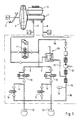
- the brake 1 has a master cylinder 1, which is connected to a reservoir 2 and from a brake pedal 3 via a vacuum brake booster 4 can be actuated.
- the brake booster 4 is more active Brake booster trained. That means that even without Actuation of the brake pedal 3 of the brake booster 4 in is able to control the actuating piston by electrical control to move the master cylinder 1 and in the brake system to build up some pressure. From the master cylinder 1 run two brake lines 5 and 6 to the respective Brake circuits. Only the brake circuit I is shown in detail, where brake circuit II is either identical can be or for example in a brake system with traction control and front axle-rear axle brake circuit division only with an anti-lock device can be provided.
- the brake circuit I thus runs from Master cylinder 1 via the brake line 5, a isolating valve 7 and two brake branch lines 8 and 9, each with an inlet valve 10 and 11 to the wheel brakes 12 and 13.
- a return branch 14 or 15 via an outlet valve 16 or 17 to a return line 18, which is connected to a low-pressure accumulator 19 is.
- the low pressure accumulator 19 is a first suction line 20 with the suction side of a self-priming Return pump 21 connected.
- This has a second Suction line 22, in which an electromagnetically operated Switch valve 23 is inserted.
- the second suction line 22 is to the brake line 5 between the master cylinder 1 and Isolation valve 7 connected.
- a pressure line 25 connects the pressure side of the return pump 21 with the brake line 5 between isolating valve 7 and inlet valves 10 and 11.
- the brake system works with anti-lock control according to the return principle, which is known per se.
- the electromagnetic switching valve 23 remains closed and the isolation valve 7 remains open. Only the intake valves 10 and 11 and the exhaust valves 16 and 17 are on Known way for pressure control in the wheel brakes 12 and 13th switched.
- the return pump 21 spends this in the low pressure accumulator 19 pressure medium discharged via the pressure line 25 back into the brake line 5 between the isolation valve 7 and the intake valves 10 and 11.
- the isolation valve 7 With active braking, for example traction control or an active brake intervention for the purpose a yaw moment control, the isolation valve 7 is closed.
- the brake booster 4 actuates the master cylinder 1, so that there is a pressure medium pressure through the brake line 5 in the second suction line 22 to electromagnetic actuated switching valve 23 reproduces.
- this is designed as an SG valve, whereby the valve lifter 44 in the valve closing direction of one Compression spring 45 is acted upon.
- the tip of the valve lifter 44 has a closing member 46, which has a valve seat 47 cooperates, which is integrally formed on a valve body 48 is.
- the valve body 48 is in a metallic sleeve 49, which is axially displaceable in the bore 50 is led.
- the metallic sleeve 59 is opposite one another the compression spring 45 very weak compression spring 51 applied to the plunger 44.
- the valve body 48 itself has a central throttle point 52, which by engaging the valve closing member 46 on the valve seat 47 is closed.
- the valve body 48 serves as Closing member for a further valve passage 53, which a significantly larger compared to the throttle point 52 Has cross section.
- the tappet side of the valve body 48 is the inlet chamber 54 of the Valve arranged while on the other side of the throttle 52 and the valve passage 53, the outlet chamber 55 is arranged.
- This electromagnetically operated switching valve is suitable especially for those braking systems that have an exhaustible Pre-charging device and with a self-priming Return pump are equipped. This explains how follows: If a pre-charge is running for the purpose of active braking, so is fixed by a solenoid on the plunger 44 rigid Magnet armature moves so that the closing member 46th takes off from its valve seat 47. Because of the between inlet chamber 54 and the outlet chamber 55 prevailing pressure gradient however, the valve body 48 remains in its illustrated Position in which he the valve passage 53 larger cross section closes. The subpoena can accordingly only take place via the throttle point 52, so that at the suction side of the return pump is not a big one from the start Can build up pressure, as this is the incoming pressure medium immediately promotes further.
- the precharging device is exhausted and thus the inlet chamber 54 is depressurized, so the Valve body 48 from the compression spring 51 back to the closing member 48 of the plunger 44 pushed, causing the valve passage 53 is opened. In this case it can continue sucking return pump your pressure medium over a substantial larger opening cross-section, so that throttling losses be avoided during further suction.
Landscapes
- Physics & Mathematics (AREA)
- Engineering & Computer Science (AREA)
- Fluid Mechanics (AREA)
- Transportation (AREA)
- Mechanical Engineering (AREA)
- Electromagnetism (AREA)
- Regulating Braking Force (AREA)
Claims (3)
- Système de freinage hydraulique à régulation antipatinage au freinage, muni d'un dispositif actif (4) de gavage, comportant un maítre-cylindre (1) relié à un réservoir (2), comportant au moins un frein de roue (12, 13) relié au maítre-cylindre (1) via une conduite de frein (5), comportant une pompe de renvoi (21) reliée au frein de roue (12, 13) par l'intermédiaire d'une première conduite d'aspiration (20), et reliée au dispositif de gavage (4) par l'intermédiaire d'une seconde conduite d'aspiration, des moyens (23) étant agencés dans la seconde conduite d'aspiration (22), pilotant l'alimentation en fluide de pression du dispositif de gavage (4) au côté aspiration de la pompe de renvoi (21) pendant le freinage actif, caractérisé en ce que le dispositif de gavage (4) est configuré en tant qu'amplificateur d'effort de freinage actif aménagé en amont du maítre-cylindre (1), et en ce que, pendant le freinage actif, les moyens (23) régulent l'alimentation en fluide de pression, du dispositif de gavage (4) vers le côté aspiration de la pompe de renvoi (21), en fonction de l'écart de pression régnant dans la seconde conduite d'aspiration (22) de la pompe de renvoi auto-amorçante (21).
- Système de freinage selon la revendication 1, caractérisé en ce que, les moyens (23) consistent en une soupape (23) à commande électromagnétique comprenant un étranglement (52) pouvant être commuté hydrauliquement.
- Système de freinage selon la revendication 2, caractérisé en ce que la soupape (23) à commande électromagnétique comporte un poussoir (44) qui, à l'état hors tension, obture l'étranglement (52) s'étendant à travers le corps de la soupape (48) guidé de façon coulissante, le corps de soupape (48) contrôlant un passage (53) de soupape qui est opposé au poussoir (44), et étant soumis à l'action d'un ressort de pression (51) agissant en direction du poussoir (44).
Applications Claiming Priority (3)
| Application Number | Priority Date | Filing Date | Title |
|---|---|---|---|
| DE19626304 | 1996-07-01 | ||
| DE19626304A DE19626304A1 (de) | 1996-07-01 | 1996-07-01 | Hydraulische Bremsanlage mit einer Vorladeeinrichtung |
| PCT/EP1997/003295 WO1998000322A1 (fr) | 1996-07-01 | 1997-06-24 | Installation de freinage hydraulique pourvue d'un dispositif de precharge |
Publications (2)
| Publication Number | Publication Date |
|---|---|
| EP0907535A1 EP0907535A1 (fr) | 1999-04-14 |
| EP0907535B1 true EP0907535B1 (fr) | 2000-09-13 |
Family
ID=7798517
Family Applications (1)
| Application Number | Title | Priority Date | Filing Date |
|---|---|---|---|
| EP97930387A Expired - Lifetime EP0907535B1 (fr) | 1996-07-01 | 1997-06-24 | Installation de freinage hydraulique pourvue d'un dispositif de precharge |
Country Status (5)
| Country | Link |
|---|---|
| US (1) | US6796619B1 (fr) |
| EP (1) | EP0907535B1 (fr) |
| JP (1) | JP2001503697A (fr) |
| DE (2) | DE19626304A1 (fr) |
| WO (1) | WO1998000322A1 (fr) |
Families Citing this family (13)
| Publication number | Priority date | Publication date | Assignee | Title |
|---|---|---|---|---|
| DE19807749A1 (de) * | 1998-02-24 | 1999-09-02 | Daimler Chrysler Ag | Verfahren zur Bestimmung des Abschaltkriteriums einer Bremsmittelpumpe in einer Fahrzeugbremsanlage |
| DE10010734A1 (de) * | 2000-03-04 | 2001-09-06 | Continental Teves Ag & Co Ohg | Elektromagnetventil, insbesondere für schlupfgeregelte Kraftfahrzeugbremsanlagen |
| KR100420007B1 (ko) * | 2001-04-25 | 2004-03-02 | 노영쇠 | 안트라사이클린 유도체 및 이를 포함하는 항암제 |
| DE102005033868A1 (de) * | 2005-07-20 | 2007-01-25 | Robert Bosch Gmbh | Vorrichtung zum Aufbau von Bremskraft in einem Bremssystem eines Fahrzeugs |
| DE102006042930A1 (de) * | 2005-12-21 | 2007-11-22 | Continental Teves Ag & Co. Ohg | Verfahren zum Betrieb einer hydraulischen Bremsanlage für Kraftfahrzeuge |
| DE102006013660A1 (de) * | 2006-01-11 | 2007-07-12 | Continental Teves Ag & Co. Ohg | Elektromagnetventil |
| DE102008014099B4 (de) * | 2007-03-27 | 2012-08-23 | Mando Corp. | Ventil für ein Antiblockierbremssystem |
| US7866625B2 (en) * | 2007-10-11 | 2011-01-11 | Mando Corporation | Solenoid valve for brake system |
| KR101187197B1 (ko) * | 2007-10-11 | 2012-10-02 | 주식회사 만도 | 브레이크시스템용 솔레노이드밸브 |
| DE102008019148A1 (de) * | 2008-04-16 | 2009-10-22 | Lucas Automotive Gmbh | Druckerzeuger einer hydraulischen Fahrzeug-Bremsanlage und Betriebsverfahren |
| DE102009055340A1 (de) * | 2009-12-28 | 2011-06-30 | Robert Bosch GmbH, 70469 | Ventilmodul, insbesondere Magnetventil für ein Bremssystem eines Kraftfahrzeugs, Verfahren zur Herstellung eines Ventilmoduls |
| DE102011076556A1 (de) * | 2011-05-26 | 2012-11-29 | Continental Teves Ag & Co. Ohg | Elektromagnetventil, insbesondere für schlupfgeregelte Kraftfahrzeugbremsanlagen |
| US20150100189A1 (en) * | 2013-10-07 | 2015-04-09 | Ford Global Technologies, Llc | Vehicle-to-infrastructure communication |
Family Cites Families (25)
| Publication number | Priority date | Publication date | Assignee | Title |
|---|---|---|---|---|
| US2914086A (en) * | 1954-11-16 | 1959-11-24 | Controls Co Of America | Valve device |
| FR2275715A1 (fr) * | 1974-06-20 | 1976-01-16 | Oswald Herve | Electrovanne a commande assistee interne |
| JPS5817275A (ja) * | 1981-07-24 | 1983-02-01 | Toshiba Corp | パイロツト弁装置 |
| DE3337545A1 (de) * | 1983-10-15 | 1985-04-25 | Robert Bosch Gmbh, 7000 Stuttgart | Hydraulische bremsanlage |
| DE4017873A1 (de) * | 1990-06-02 | 1991-12-05 | Bosch Gmbh Robert | Hydraulische zweikreisbremsanlage |
| DE4017872A1 (de) | 1990-06-02 | 1991-12-05 | Bosch Gmbh Robert | Hydraulische fahrzeugbremsanlage mit antiblockiersystem und antriebsschlupfregelung |
| DE4025859A1 (de) * | 1990-08-16 | 1992-02-20 | Bosch Gmbh Robert | Hydraulische fahrzeugbremsanlage mit einer blockierschutz- und antriebsschlupfbegrenzungseinrichtung |
| DE4128091C2 (de) * | 1991-08-24 | 1998-02-26 | Teves Gmbh Alfred | Bremsanlage mit Blockierschutz- und Antriebsschlupfregelung |
| JPH0680071A (ja) * | 1992-09-03 | 1994-03-22 | Sumitomo Electric Ind Ltd | ブレーキ液圧制御装置 |
| JPH0655909U (ja) * | 1993-01-14 | 1994-08-02 | 住友電気工業株式会社 | ブレーキ液圧制御装置 |
| DE4319227A1 (de) * | 1993-06-09 | 1994-12-15 | Teves Gmbh Alfred | Hydraulische Bremsanlage mit Schlupfregelung |
| DE4329140C1 (de) * | 1993-08-30 | 1994-12-01 | Daimler Benz Ag | Bremsdruck-Steuereinrichtung |
| DE4337763A1 (de) * | 1993-11-05 | 1995-05-11 | Teves Gmbh Alfred | Druckregelventil |
| DE4409911A1 (de) * | 1994-03-23 | 1995-09-28 | Teves Gmbh Alfred | Hydraulische Bremsanlage mit Bremsschlupf- und Antriebsschlupfregelung |
| DE4415651C1 (de) * | 1994-05-04 | 1995-04-27 | Daimler Benz Ag | Bremsdruck-Steuereinrichtung |
| DE4425578A1 (de) | 1994-07-20 | 1996-01-25 | Teves Gmbh Alfred | Verfahren zum Betreiben einer blockiergeschützten Kraftfahrzeugbremsanlage |
| DE4427379C1 (de) * | 1994-08-03 | 1995-10-12 | Daimler Benz Ag | Bremsdruck-Steuereinrichtung |
| JP3365151B2 (ja) * | 1994-08-05 | 2003-01-08 | アイシン精機株式会社 | 電磁弁 |
| DE4434960A1 (de) | 1994-09-30 | 1996-04-04 | Teves Gmbh Alfred | Hydraulische Bremsanlage und Verfahren zur Druckregelung |
| DE4439904A1 (de) * | 1994-11-08 | 1996-05-09 | Teves Gmbh Alfred | Verfahren zum Betreiben einer blockiergeschützten Kraftfahrzeugbremsanlage |
| WO1996015926A1 (fr) * | 1994-11-24 | 1996-05-30 | Robert Bosch Gmbh | Systeme de soupapes a commande electromagnetique |
| DE19511455A1 (de) * | 1995-03-29 | 1996-10-02 | Bosch Gmbh Robert | Magnetventil in einer hydraulischen Bremsanlage für Kraftfahrzeuge |
| DE19529363A1 (de) | 1995-08-10 | 1997-02-13 | Bosch Gmbh Robert | Steuerbares Ventil |
| DE19530899C2 (de) * | 1995-08-23 | 2003-08-21 | Bosch Gmbh Robert | Magnetventil, insbesondere für eine schlupfgeregelte, hydraulische Bremsanlage für Kraftfahrzeuge |
| DE19541913A1 (de) | 1995-11-10 | 1997-05-15 | Teves Gmbh Alfred | Antriebsaggregat, insbesondere für eine Scheibenwischeranlage |
-
1996
- 1996-07-01 DE DE19626304A patent/DE19626304A1/de not_active Withdrawn
-
1997
- 1997-06-24 DE DE59702352T patent/DE59702352D1/de not_active Expired - Lifetime
- 1997-06-24 EP EP97930387A patent/EP0907535B1/fr not_active Expired - Lifetime
- 1997-06-24 JP JP50381798A patent/JP2001503697A/ja active Pending
- 1997-06-24 WO PCT/EP1997/003295 patent/WO1998000322A1/fr active IP Right Grant
- 1997-06-24 US US09/214,394 patent/US6796619B1/en not_active Expired - Fee Related
Also Published As
| Publication number | Publication date |
|---|---|
| DE19626304A1 (de) | 1998-01-08 |
| DE59702352D1 (de) | 2000-10-19 |
| EP0907535A1 (fr) | 1999-04-14 |
| WO1998000322A1 (fr) | 1998-01-08 |
| US6796619B1 (en) | 2004-09-28 |
| JP2001503697A (ja) | 2001-03-21 |
Similar Documents
| Publication | Publication Date | Title |
|---|---|---|
| DE3731603C2 (de) | Blockiergeschützte Fahrzeugbremsanlage | |
| EP0504334B1 (fr) | Systeme de freinage avec installation servant a la fois pour la regulation du glissement au freinage et pour la regulation du glissement a l'entrainement | |
| EP0907535B1 (fr) | Installation de freinage hydraulique pourvue d'un dispositif de precharge | |
| DE102008058240A1 (de) | Bremssystem für Kraftfahrzeuge | |
| DE4110851A1 (de) | Kraftfahrzeugbremsanlage mit bremsschlupf- und antriebsschlupfabhaengiger regelung des bremsdruckes | |
| EP0928266B1 (fr) | Systeme de freinage hydraulique pour vehicule | |
| DE19626289B4 (de) | Hydraulische Bremsanlage mit einer Rückförderpumpe | |
| WO1989008573A2 (fr) | Systeme de freinage | |
| EP2268516B1 (fr) | Générateur de pression d un dispositif de freinage hydraulique de véhicule et procédé de fonctionnement associé | |
| DE4335676A1 (de) | Bremsanlage für Kraftfahrzeuge | |
| WO1997026168A1 (fr) | Systeme de freinage hydraulique avec dispositif de freinage actif | |
| DE19523946A1 (de) | Schlupfgeregelte hydraulische Bremsanlage mit Ladepumpe | |
| DE4011329A1 (de) | Hydraulische zweikreisbremsanlage | |
| DE10041721B4 (de) | Elektromagnetisches Ventil und Verwendung desselben in einem Hydraulikkreis | |
| DE4021454A1 (de) | Hydraulische bremsanlage | |
| EP0749380B1 (fr) | Systeme de freinage hydraulique a regulation antipatinage et antiblocage | |
| DE3812832C1 (fr) | ||
| DE4024627A1 (de) | Hydraulische fahrzeugbremsanlage mit blockierschutz- und antriebsschlupfbegrenzungseinrichtung | |
| DE19727654B4 (de) | Hydraulisches Ventil | |
| DE4009303A1 (de) | Hydraulische zweikreisbremsanlage | |
| DE102008010975B4 (de) | Hydraulikbremsanlage mit elektronischer Bremsdruckregelung für ein Kraftfahrzeug | |
| DE3807452A1 (de) | Bremsanlage | |
| DE19918112B4 (de) | Hydraulische Kraftfahrzeugbremsanlage mit Radschlupfregelung | |
| DE19541381A1 (de) | Bremsanlage mit einer Einrichtung zur Aktivbremsung | |
| DE4437701A1 (de) | Schlupfgeregelte hydraulische Bremsanlage |
Legal Events
| Date | Code | Title | Description |
|---|---|---|---|
| PUAI | Public reference made under article 153(3) epc to a published international application that has entered the european phase |
Free format text: ORIGINAL CODE: 0009012 |
|
| 17P | Request for examination filed |
Effective date: 19990201 |
|
| AK | Designated contracting states |
Kind code of ref document: A1 Designated state(s): DE FR GB |
|
| 17Q | First examination report despatched |
Effective date: 19990427 |
|
| RAP1 | Party data changed (applicant data changed or rights of an application transferred) |
Owner name: CONTINENTAL TEVES AG & CO. OHG |
|
| GRAG | Despatch of communication of intention to grant |
Free format text: ORIGINAL CODE: EPIDOS AGRA |
|
| GRAG | Despatch of communication of intention to grant |
Free format text: ORIGINAL CODE: EPIDOS AGRA |
|
| GRAH | Despatch of communication of intention to grant a patent |
Free format text: ORIGINAL CODE: EPIDOS IGRA |
|
| GRAH | Despatch of communication of intention to grant a patent |
Free format text: ORIGINAL CODE: EPIDOS IGRA |
|
| GRAA | (expected) grant |
Free format text: ORIGINAL CODE: 0009210 |
|
| AK | Designated contracting states |
Kind code of ref document: B1 Designated state(s): DE FR GB |
|
| GBT | Gb: translation of ep patent filed (gb section 77(6)(a)/1977) |
Effective date: 20000914 |
|
| REF | Corresponds to: |
Ref document number: 59702352 Country of ref document: DE Date of ref document: 20001019 |
|
| ET | Fr: translation filed | ||
| PLBE | No opposition filed within time limit |
Free format text: ORIGINAL CODE: 0009261 |
|
| STAA | Information on the status of an ep patent application or granted ep patent |
Free format text: STATUS: NO OPPOSITION FILED WITHIN TIME LIMIT |
|
| 26N | No opposition filed | ||
| REG | Reference to a national code |
Ref country code: GB Ref legal event code: IF02 |
|
| PGFP | Annual fee paid to national office [announced via postgrant information from national office to epo] |
Ref country code: GB Payment date: 20050523 Year of fee payment: 9 |
|
| PG25 | Lapsed in a contracting state [announced via postgrant information from national office to epo] |
Ref country code: GB Free format text: LAPSE BECAUSE OF NON-PAYMENT OF DUE FEES Effective date: 20060624 |
|
| GBPC | Gb: european patent ceased through non-payment of renewal fee |
Effective date: 20060624 |
|
| PGFP | Annual fee paid to national office [announced via postgrant information from national office to epo] |
Ref country code: DE Payment date: 20140630 Year of fee payment: 18 |
|
| PGFP | Annual fee paid to national office [announced via postgrant information from national office to epo] |
Ref country code: FR Payment date: 20140619 Year of fee payment: 18 |
|
| REG | Reference to a national code |
Ref country code: DE Ref legal event code: R119 Ref document number: 59702352 Country of ref document: DE |
|
| REG | Reference to a national code |
Ref country code: FR Ref legal event code: ST Effective date: 20160229 |
|
| PG25 | Lapsed in a contracting state [announced via postgrant information from national office to epo] |
Ref country code: DE Free format text: LAPSE BECAUSE OF NON-PAYMENT OF DUE FEES Effective date: 20160101 |
|
| PG25 | Lapsed in a contracting state [announced via postgrant information from national office to epo] |
Ref country code: FR Free format text: LAPSE BECAUSE OF NON-PAYMENT OF DUE FEES Effective date: 20150630 |