EP0907535B1 - Hydraulic brake system with a precharging device - Google Patents
Hydraulic brake system with a precharging device Download PDFInfo
- Publication number
- EP0907535B1 EP0907535B1 EP97930387A EP97930387A EP0907535B1 EP 0907535 B1 EP0907535 B1 EP 0907535B1 EP 97930387 A EP97930387 A EP 97930387A EP 97930387 A EP97930387 A EP 97930387A EP 0907535 B1 EP0907535 B1 EP 0907535B1
- Authority
- EP
- European Patent Office
- Prior art keywords
- brake
- valve
- return pump
- brake system
- pressure
- Prior art date
- Legal status (The legal status is an assumption and is not a legal conclusion. Google has not performed a legal analysis and makes no representation as to the accuracy of the status listed.)
- Expired - Lifetime
Links
- 230000006835 compression Effects 0.000 claims description 5
- 238000007906 compression Methods 0.000 claims description 5
- 239000012530 fluid Substances 0.000 claims description 3
- 238000011144 upstream manufacturing Methods 0.000 claims 1
- 238000002955 isolation Methods 0.000 description 4
- 230000000994 depressogenic effect Effects 0.000 description 1
- 230000037452 priming Effects 0.000 description 1
Images

Classifications
-
- B—PERFORMING OPERATIONS; TRANSPORTING
- B60—VEHICLES IN GENERAL
- B60T—VEHICLE BRAKE CONTROL SYSTEMS OR PARTS THEREOF; BRAKE CONTROL SYSTEMS OR PARTS THEREOF, IN GENERAL; ARRANGEMENT OF BRAKING ELEMENTS ON VEHICLES IN GENERAL; PORTABLE DEVICES FOR PREVENTING UNWANTED MOVEMENT OF VEHICLES; VEHICLE MODIFICATIONS TO FACILITATE COOLING OF BRAKES
- B60T8/00—Arrangements for adjusting wheel-braking force to meet varying vehicular or ground-surface conditions, e.g. limiting or varying distribution of braking force
- B60T8/32—Arrangements for adjusting wheel-braking force to meet varying vehicular or ground-surface conditions, e.g. limiting or varying distribution of braking force responsive to a speed condition, e.g. acceleration or deceleration
- B60T8/34—Arrangements for adjusting wheel-braking force to meet varying vehicular or ground-surface conditions, e.g. limiting or varying distribution of braking force responsive to a speed condition, e.g. acceleration or deceleration having a fluid pressure regulator responsive to a speed condition
- B60T8/48—Arrangements for adjusting wheel-braking force to meet varying vehicular or ground-surface conditions, e.g. limiting or varying distribution of braking force responsive to a speed condition, e.g. acceleration or deceleration having a fluid pressure regulator responsive to a speed condition connecting the brake actuator to an alternative or additional source of fluid pressure, e.g. traction control systems
- B60T8/4809—Traction control, stability control, using both the wheel brakes and other automatic braking systems
- B60T8/4827—Traction control, stability control, using both the wheel brakes and other automatic braking systems in hydraulic brake systems
- B60T8/4863—Traction control, stability control, using both the wheel brakes and other automatic braking systems in hydraulic brake systems closed systems
- B60T8/4872—Traction control, stability control, using both the wheel brakes and other automatic braking systems in hydraulic brake systems closed systems pump-back systems
- B60T8/4881—Traction control, stability control, using both the wheel brakes and other automatic braking systems in hydraulic brake systems closed systems pump-back systems having priming means
-
- B—PERFORMING OPERATIONS; TRANSPORTING
- B60—VEHICLES IN GENERAL
- B60T—VEHICLE BRAKE CONTROL SYSTEMS OR PARTS THEREOF; BRAKE CONTROL SYSTEMS OR PARTS THEREOF, IN GENERAL; ARRANGEMENT OF BRAKING ELEMENTS ON VEHICLES IN GENERAL; PORTABLE DEVICES FOR PREVENTING UNWANTED MOVEMENT OF VEHICLES; VEHICLE MODIFICATIONS TO FACILITATE COOLING OF BRAKES
- B60T8/00—Arrangements for adjusting wheel-braking force to meet varying vehicular or ground-surface conditions, e.g. limiting or varying distribution of braking force
- B60T8/32—Arrangements for adjusting wheel-braking force to meet varying vehicular or ground-surface conditions, e.g. limiting or varying distribution of braking force responsive to a speed condition, e.g. acceleration or deceleration
- B60T8/34—Arrangements for adjusting wheel-braking force to meet varying vehicular or ground-surface conditions, e.g. limiting or varying distribution of braking force responsive to a speed condition, e.g. acceleration or deceleration having a fluid pressure regulator responsive to a speed condition
- B60T8/36—Arrangements for adjusting wheel-braking force to meet varying vehicular or ground-surface conditions, e.g. limiting or varying distribution of braking force responsive to a speed condition, e.g. acceleration or deceleration having a fluid pressure regulator responsive to a speed condition including a pilot valve responding to an electromagnetic force
- B60T8/3615—Electromagnetic valves specially adapted for anti-lock brake and traction control systems
- B60T8/363—Electromagnetic valves specially adapted for anti-lock brake and traction control systems in hydraulic systems
-
- B—PERFORMING OPERATIONS; TRANSPORTING
- B60—VEHICLES IN GENERAL
- B60T—VEHICLE BRAKE CONTROL SYSTEMS OR PARTS THEREOF; BRAKE CONTROL SYSTEMS OR PARTS THEREOF, IN GENERAL; ARRANGEMENT OF BRAKING ELEMENTS ON VEHICLES IN GENERAL; PORTABLE DEVICES FOR PREVENTING UNWANTED MOVEMENT OF VEHICLES; VEHICLE MODIFICATIONS TO FACILITATE COOLING OF BRAKES
- B60T8/00—Arrangements for adjusting wheel-braking force to meet varying vehicular or ground-surface conditions, e.g. limiting or varying distribution of braking force
- B60T8/32—Arrangements for adjusting wheel-braking force to meet varying vehicular or ground-surface conditions, e.g. limiting or varying distribution of braking force responsive to a speed condition, e.g. acceleration or deceleration
- B60T8/34—Arrangements for adjusting wheel-braking force to meet varying vehicular or ground-surface conditions, e.g. limiting or varying distribution of braking force responsive to a speed condition, e.g. acceleration or deceleration having a fluid pressure regulator responsive to a speed condition
- B60T8/40—Arrangements for adjusting wheel-braking force to meet varying vehicular or ground-surface conditions, e.g. limiting or varying distribution of braking force responsive to a speed condition, e.g. acceleration or deceleration having a fluid pressure regulator responsive to a speed condition comprising an additional fluid circuit including fluid pressurising means for modifying the pressure of the braking fluid, e.g. including wheel driven pumps for detecting a speed condition, or pumps which are controlled by means independent of the braking system
- B60T8/404—Control of the pump unit
- B60T8/4054—Control of the pump unit involving the delivery pressure control
-
- B—PERFORMING OPERATIONS; TRANSPORTING
- B60—VEHICLES IN GENERAL
- B60T—VEHICLE BRAKE CONTROL SYSTEMS OR PARTS THEREOF; BRAKE CONTROL SYSTEMS OR PARTS THEREOF, IN GENERAL; ARRANGEMENT OF BRAKING ELEMENTS ON VEHICLES IN GENERAL; PORTABLE DEVICES FOR PREVENTING UNWANTED MOVEMENT OF VEHICLES; VEHICLE MODIFICATIONS TO FACILITATE COOLING OF BRAKES
- B60T8/00—Arrangements for adjusting wheel-braking force to meet varying vehicular or ground-surface conditions, e.g. limiting or varying distribution of braking force
- B60T8/32—Arrangements for adjusting wheel-braking force to meet varying vehicular or ground-surface conditions, e.g. limiting or varying distribution of braking force responsive to a speed condition, e.g. acceleration or deceleration
- B60T8/34—Arrangements for adjusting wheel-braking force to meet varying vehicular or ground-surface conditions, e.g. limiting or varying distribution of braking force responsive to a speed condition, e.g. acceleration or deceleration having a fluid pressure regulator responsive to a speed condition
- B60T8/40—Arrangements for adjusting wheel-braking force to meet varying vehicular or ground-surface conditions, e.g. limiting or varying distribution of braking force responsive to a speed condition, e.g. acceleration or deceleration having a fluid pressure regulator responsive to a speed condition comprising an additional fluid circuit including fluid pressurising means for modifying the pressure of the braking fluid, e.g. including wheel driven pumps for detecting a speed condition, or pumps which are controlled by means independent of the braking system
- B60T8/404—Control of the pump unit
- B60T8/4059—Control of the pump unit involving the rate of delivery
Definitions
- the present invention relates to a hydraulic Brake system according to the preamble of claim 1.
- a brake system is for example from DE 40 25 859 A1 known.
- the known brake system has one Front axle-rear axle brake circuit division, where a Brake circuit of a non-driven axle and one Brake circuit is assigned to a driven axis.
- the Brake circuit of the driven axle is with a device equipped for traction control.
- a Traction control is a form of active braking because a brake intervention without operating the brake pedal is made.
- Other forms of active braking are for example brake interventions for yaw moment control without driver involvement.
- the known brake system works in the case of brake slip control according to the return feed principle and is for traction control with a pre-charge pump for the return pump fitted.
- the precharge pump is with its suction side connected to the reservoir of the brake system and with its pressure side via a hydraulically operated switching valve connected to the suction side of the return pump. If the delivery pressure of the return pump reaches the maximum pressure, which in the braking system during traction control is provided, flows through the funded Pressure medium a pressure relief valve and gets into the Control line for the hydraulically operated switching valve between the pre-charge pump and the return pump.
- the traction control system does not develop as long Pre-charge volume and passed on to the return pump until the pressure in the control line has dropped so far that the switching valve opens again.
- the point of this measure is the one that should be avoided, unnecessary pressure medium volume to be conveyed by the return pump.
- the return pump should only generate pressure if this is also needed. So instead of superfluous funding Volume but a pressure relief valve in the reservoir Let the brake system drain, the suction side the return pump is blocked until it is pumped again necessary is.
- DE 43 29 140 C is a hydraulic brake position with Brake slip control and an active brake booster known. In DE 43 29 140 C there is no statement about the return pumps and the switching valves.
- WO 96/02409 A From WO 96/02409 A is also a hydraulic Brake system with brake slip control and an active one Brake booster known. In WO 96/02409 A there is also no statements about the return pumps and the switching valves.
- the active brake booster used to fill the wheel brakes.
- To The brake booster is finished with the priming connected to the suction side of the return pumps.
- WO96 / 15926 A is a hydraulic brake system Brake slip control known according to the return feed principle.
- the Return pumps are self-priming in this system executed.
- the Return pumps brake fluid from the master cylinder reservoir through the master cylinder and a between Master cylinder and return pumps arranged valve sucked in.
- To open these valves when stepped on Brake pedal to simplify (less force) or this Making valves smaller is the use of pilot valves provided in which at a large Pressure drop between master cylinder and return pumps (depressed brake pedal) first as pilot valve and then the main valve only when there is a lower pressure drop opens with a large passage.
- the big passage will needed around the return pumps during active braking to be sucked in as losslessly as possible because there are none Subpoena there.
- the present invention is therefore based on the object a hydraulic brake system of the type mentioned create, which is provided with an active brake booster for active braking, and in which the return pump reduced one Is subject to wear. This task is accomplished by the Features of claim 1 solved.
- the principle of the invention lies in active braking from the outset the pressure on the suction side of the return pump not to let it rise so high that Damage can occur by the pressure medium supply during a pre-charge depending on the pressure drop between the pre-charging device and the suction side of the return pump is controlled. Decisive for a reduction in Pressure medium supply is therefore no longer the delivery pressure of the Return pump.
- a solenoid valve with a hydraulically insertable throttle point is particularly suitable for the pressure medium flow to the suction side limit the pump.
- the throttle point can be designed so that it Opening the solenoid valve is effective as long as between the precharging device and the return pump a pressure drop prevails. If the pre-charge is finished, for example when using an active brake booster after a while the throttle can be applied so that a larger valve passage opens. Then namely with the self-priming return pump pressure medium over a large opening cross-section of the valve be sucked up.
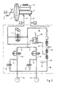
- the brake 1 has a master cylinder 1, which is connected to a reservoir 2 and from a brake pedal 3 via a vacuum brake booster 4 can be actuated.
- the brake booster 4 is more active Brake booster trained. That means that even without Actuation of the brake pedal 3 of the brake booster 4 in is able to control the actuating piston by electrical control to move the master cylinder 1 and in the brake system to build up some pressure. From the master cylinder 1 run two brake lines 5 and 6 to the respective Brake circuits. Only the brake circuit I is shown in detail, where brake circuit II is either identical can be or for example in a brake system with traction control and front axle-rear axle brake circuit division only with an anti-lock device can be provided.
- the brake circuit I thus runs from Master cylinder 1 via the brake line 5, a isolating valve 7 and two brake branch lines 8 and 9, each with an inlet valve 10 and 11 to the wheel brakes 12 and 13.
- a return branch 14 or 15 via an outlet valve 16 or 17 to a return line 18, which is connected to a low-pressure accumulator 19 is.
- the low pressure accumulator 19 is a first suction line 20 with the suction side of a self-priming Return pump 21 connected.
- This has a second Suction line 22, in which an electromagnetically operated Switch valve 23 is inserted.
- the second suction line 22 is to the brake line 5 between the master cylinder 1 and Isolation valve 7 connected.
- a pressure line 25 connects the pressure side of the return pump 21 with the brake line 5 between isolating valve 7 and inlet valves 10 and 11.
- the brake system works with anti-lock control according to the return principle, which is known per se.
- the electromagnetic switching valve 23 remains closed and the isolation valve 7 remains open. Only the intake valves 10 and 11 and the exhaust valves 16 and 17 are on Known way for pressure control in the wheel brakes 12 and 13th switched.
- the return pump 21 spends this in the low pressure accumulator 19 pressure medium discharged via the pressure line 25 back into the brake line 5 between the isolation valve 7 and the intake valves 10 and 11.
- the isolation valve 7 With active braking, for example traction control or an active brake intervention for the purpose a yaw moment control, the isolation valve 7 is closed.
- the brake booster 4 actuates the master cylinder 1, so that there is a pressure medium pressure through the brake line 5 in the second suction line 22 to electromagnetic actuated switching valve 23 reproduces.
- this is designed as an SG valve, whereby the valve lifter 44 in the valve closing direction of one Compression spring 45 is acted upon.
- the tip of the valve lifter 44 has a closing member 46, which has a valve seat 47 cooperates, which is integrally formed on a valve body 48 is.
- the valve body 48 is in a metallic sleeve 49, which is axially displaceable in the bore 50 is led.
- the metallic sleeve 59 is opposite one another the compression spring 45 very weak compression spring 51 applied to the plunger 44.
- the valve body 48 itself has a central throttle point 52, which by engaging the valve closing member 46 on the valve seat 47 is closed.
- the valve body 48 serves as Closing member for a further valve passage 53, which a significantly larger compared to the throttle point 52 Has cross section.
- the tappet side of the valve body 48 is the inlet chamber 54 of the Valve arranged while on the other side of the throttle 52 and the valve passage 53, the outlet chamber 55 is arranged.
- This electromagnetically operated switching valve is suitable especially for those braking systems that have an exhaustible Pre-charging device and with a self-priming Return pump are equipped. This explains how follows: If a pre-charge is running for the purpose of active braking, so is fixed by a solenoid on the plunger 44 rigid Magnet armature moves so that the closing member 46th takes off from its valve seat 47. Because of the between inlet chamber 54 and the outlet chamber 55 prevailing pressure gradient however, the valve body 48 remains in its illustrated Position in which he the valve passage 53 larger cross section closes. The subpoena can accordingly only take place via the throttle point 52, so that at the suction side of the return pump is not a big one from the start Can build up pressure, as this is the incoming pressure medium immediately promotes further.
- the precharging device is exhausted and thus the inlet chamber 54 is depressurized, so the Valve body 48 from the compression spring 51 back to the closing member 48 of the plunger 44 pushed, causing the valve passage 53 is opened. In this case it can continue sucking return pump your pressure medium over a substantial larger opening cross-section, so that throttling losses be avoided during further suction.
Landscapes
- Physics & Mathematics (AREA)
- Engineering & Computer Science (AREA)
- Fluid Mechanics (AREA)
- Transportation (AREA)
- Mechanical Engineering (AREA)
- Electromagnetism (AREA)
- Regulating Braking Force (AREA)
Description
Die vorliegende Erfindung betrifft eine hydraulische Bremsanlage gemäß dem Oberbegriff des Anspruchs 1. Eine derartige Bremsanlage ist beispielsweise aus der DE 40 25 859 A1 bekannt. Die bekannte Bremsanlage weist eine Vorderachs-Hinterachs-Bremskreisaufteilung auf, wobei ein Bremskreis einer nicht angetriebenen Achse und ein Bremskreis einer angetriebenen Achse zugeordnet ist. Der Bremskreis der angetriebenen Achse ist mit einer Einrichtung zur Antriebsschlupfregelung ausgestattet. Eine Antriebsschlupf-regelung ist eine Form der Aktivbremsung, da ein Bremseneingriff ohne Betätigung des Bremspedals vorgenommen wird. Weitere Formen der Aktivbremsung sind beispielsweise Bremseneingriffe zur Giermomentenregelung ohne Beteiligung des Fahrers.The present invention relates to a hydraulic Brake system according to the preamble of claim 1. A Such a brake system is for example from DE 40 25 859 A1 known. The known brake system has one Front axle-rear axle brake circuit division, where a Brake circuit of a non-driven axle and one Brake circuit is assigned to a driven axis. The Brake circuit of the driven axle is with a device equipped for traction control. A Traction control is a form of active braking because a brake intervention without operating the brake pedal is made. Other forms of active braking are for example brake interventions for yaw moment control without driver involvement.
Bei einer Bremsschlupfregelung arbeitet die bekannte Bremsanlage nach dem Rückförderprinzip und ist zur Antriebsschlupfregelung mit einer Vorladepumpe für die Rückförderpumpe ausgestattet. Die Vorladepumpe ist mit ihrer Saugseite an den Vorratsbehälter der Bremsanlage angeschlossen und mit ihrer Druckseite über ein hydraulisch betätigtes Schaltventil mit der Saugseite der Rückförderpumpe verbunden. Wenn der Förderdruck der Rückförderpumpe den Maximaldruck erreicht, welcher im Bremssystem während einer Antriebsschlupfregelung vorgesehen ist, durchströmt das geförderte Druckmittel ein Druckbegrenzungsventil und gelangt in die Steuerleitung für das hydraulisch betätigte Schaltventil zwischen der Vorladepumpe und der Rückförderpumpe. Im weiteren Verlauf der Antriebsschlupfregelung wird so lange kein Vorladevolumen und an die Rückförderpumpe weitergegeben, bis der Druck in der Steuerleitung soweit abgesunken ist, daß das Schaltventil wieder öffnet. Der Sinn dieser Maßnahme ist derjenige, daß vermieden werden soll, unnötiges Druckmittelvolumen durch die Rückförderpumpe fördern zu lassen. Die Rückförderpumpe soll nur dann einen Druck erzeugen, wenn dieser auch benötigt wird. Anstatt also überflüssig gefördertes Volumen aber ein Überdruckventil in den Vorratsbehälter der Bremsanlage abfließen zu lassen, wird die Saugseite der Rückförderpumpe so lange gesperrt, bis wieder eine Förderung notwendig ist.The known brake system works in the case of brake slip control according to the return feed principle and is for traction control with a pre-charge pump for the return pump fitted. The precharge pump is with its suction side connected to the reservoir of the brake system and with its pressure side via a hydraulically operated switching valve connected to the suction side of the return pump. If the delivery pressure of the return pump reaches the maximum pressure, which in the braking system during traction control is provided, flows through the funded Pressure medium a pressure relief valve and gets into the Control line for the hydraulically operated switching valve between the pre-charge pump and the return pump. In the further The traction control system does not develop as long Pre-charge volume and passed on to the return pump until the pressure in the control line has dropped so far that the switching valve opens again. The point of this measure is the one that should be avoided, unnecessary pressure medium volume to be conveyed by the return pump. The return pump should only generate pressure if this is also needed. So instead of superfluous funding Volume but a pressure relief valve in the reservoir Let the brake system drain, the suction side the return pump is blocked until it is pumped again necessary is.
Aus der DE 43 29 140 C ist eine hydraulische Bremslage mit Bremsschlupfregelung und einem aktiven Bremskraftverstärker bekannt. In der DE 43 29 140 C gibt es keine Aussage über die Rückförderpumpen und die Schaltventile.From DE 43 29 140 C is a hydraulic brake position with Brake slip control and an active brake booster known. In DE 43 29 140 C there is no statement about the return pumps and the switching valves.
Bei der Verwendung eines aktiven Bremskraftverstärkers und eines Hauptzylinders als Vorladeeinrichtung wird die Rückförderpumpe durch die Vorladeeinrichtung im Aktivbremsmodus stark belastet und verschleißt vorzeitig. Große auftretende Leckagen führen dann im Extremfall zum Ausfall der Elektromotoren der Pumpen. Eine tauchdichte Ausführung der Elektromotoren wäre aber mit erheblichem Aufwand verbunden.When using an active brake booster and of a master cylinder as a precharging device Return pump through the pre-charging device in active braking mode heavily burdened and wears out prematurely. Great occurring In extreme cases, leaks then lead to the failure of the electric motors of the pumps. A submersible version of the Electric motors would be associated with considerable effort.
Aus der WO 96/02409 A ist ebenfalls eine hydraulische Bremsanlage mit Bremsschlupfregelung und einem aktiven Bremskraftverstärker bekannt. In der WO 96/02409 A gibt es ebenfalls keine Aussagen über die Rückförderpumpen und die Schaltventile.From WO 96/02409 A is also a hydraulic Brake system with brake slip control and an active one Brake booster known. In WO 96/02409 A there is also no statements about the return pumps and the switching valves.
Gemäß der Lehr dieser Schrift wird der aktive Bremskraftverstärker zum Vorfüllen der Radbremsen verwendet. Nach Beendigung des Vorfüllens wird der Bremskraftverstärker mit der Saugseite der Rückförderpumpen verbunden.According to the teaching of this document, the active brake booster used to fill the wheel brakes. To The brake booster is finished with the priming connected to the suction side of the return pumps.
Aus der WO96/15926 A ist eine hydraulische Bremsanlage mit Bremsschlupfregelung nach dem Rückförderprinzip bekannt. Die Rückförderpumpen sind bei dieser Anlage selbstansaugend ausgeführt. Während einer Aktivbremsung wird durch die Rückförderpumpen Bremsflüssigkeit aus dem Hauptzylinderreservoir durch den Hauptzylinder und ein zwischen Hauptzylinder und Rückförderpumpen angeordnetes Ventil angesaugt. Um das Öffnen dieser Ventile bei getretenem Bremspedal zu vereinfachen (weniger Kraft) bzw. diese Ventile kleiner zu bauen, ist die Anwendung von Vorsteuerventilen vorgesehen, bei welchen bei einem großen Druckgefälle zwischen Hauptzylinder und Rückförderpumpen (getretenes Bremspedal) zuerst als Vorsteuerventil und danach, erst bei einem geringeren Druckgefälle, das Hauptventil mit großem Durchlaß öffnet. Der große Durchlaß wird benötigt um die Rückförderpumpen während einer Aktivbremsung möglichst verlustfrei ansaugen zu lassen, weil es keine Vorladung gibt.From WO96 / 15926 A is a hydraulic brake system Brake slip control known according to the return feed principle. The Return pumps are self-priming in this system executed. During active braking, the Return pumps brake fluid from the master cylinder reservoir through the master cylinder and a between Master cylinder and return pumps arranged valve sucked in. To open these valves when stepped on Brake pedal to simplify (less force) or this Making valves smaller is the use of pilot valves provided in which at a large Pressure drop between master cylinder and return pumps (depressed brake pedal) first as pilot valve and then the main valve only when there is a lower pressure drop opens with a large passage. The big passage will needed around the return pumps during active braking to be sucked in as losslessly as possible because there are none Subpoena there.
Der vorliegenden Erfindung liegt daher die Aufgabe zugrunde, eine hydraulische Bremsanlage der eingangs genannten Art zu schaffen, welche mit einem aktiven Bremskraftverstärker zur Aktivbremsung versehen ist, und bei welcher die Rückförderpumpe einem veringerten Verschleiß unterworfen ist. Diese Aufgabe wird durch die Merkmale des Anspruchs 1 gelöst. The present invention is therefore based on the object a hydraulic brake system of the type mentioned create, which is provided with an active brake booster for active braking, and in which the return pump reduced one Is subject to wear. This task is accomplished by the Features of claim 1 solved.
Das Prinzip der Erfindung liegt darin, bei einer Aktivbremsung von vornherein den Druck an der Saugseite der Rückförderpumpe erst gar nicht so hoch ansteigen zu lassen, daß eine Beschädigung auftreten könne, indem die Druckmittelzufuhr während einer Vorladung abhängig vom Druckgefälle zwischen Vorladeeinrichtung und Saugseite der Rückförderpumpe gesteuert wird. Ausschlaggebend für eine Reduzierung der Druckmittelzufuhr ist also nicht mehr der Förderdruck der Rückförderpumpe.The principle of the invention lies in active braking from the outset the pressure on the suction side of the return pump not to let it rise so high that Damage can occur by the pressure medium supply during a pre-charge depending on the pressure drop between the pre-charging device and the suction side of the return pump is controlled. Decisive for a reduction in Pressure medium supply is therefore no longer the delivery pressure of the Return pump.
Ein Magnetventil mit hydraulisch einfügbarer Drosselstelle eignet sich besonders dazu, den Druckmittelstrom zur Saugseite der Pumpe zu begrenzen.A solenoid valve with a hydraulically insertable throttle point is particularly suitable for the pressure medium flow to the suction side limit the pump.
Die Drosselstelle kann dabei so gestaltet sein, daß sie bei Öffnen des Magnetventils so lange wirksam ist, wie zwischen der Vorladeeinrichtung und der Rückförderpumpe ein Druckgefälle vorherrscht. Ist die Vorladung beendet, wie es beispielsweise bei der Verwendung eines aktiven Bremskraftverstärkers nach einiger Zeit der Fall ist, kann die Drossel aufgeschaltet werden, so daß sich ein größerer Ventildurchgang öffnet. Dann nämlich kann bei der selbstansaugenden Rückförderpumpe über einen großen Öffnungsquerschnitt des Ventils Druckmittel nachgesaugt werden.The throttle point can be designed so that it Opening the solenoid valve is effective as long as between the precharging device and the return pump a pressure drop prevails. If the pre-charge is finished, for example when using an active brake booster after a while the throttle can be applied so that a larger valve passage opens. Then namely with the self-priming return pump pressure medium over a large opening cross-section of the valve be sucked up.
Eine nähere Erläuterung des Erfindungsgedankens erfolgt nun anhand der Beschreibung eines Ausführungsbeispiels der Erfindung in zwei Figuren. Es zeigt:
- Fig. 1
- eine erfindungsgemäße Bremsanlage mit einemelektromagnetisch betätigten Schaltventil in der Verbindung zwischen Vorladeeinrichtung und Rückförderpumpe,
- Fig. 2
- das elektromagnetisch betätigte Schaltventil aus Fig. 1 in vergrößerter Darstellung mit einer hydraulisch einfügbaren Drosselstelle.
- Fig. 1
- a brake system according to the invention with an electromagnetically actuated switching valve in the connection between the precharging device and the return pump,
- Fig. 2
- the electromagnetically operated switching valve from FIG. 1 in an enlarged view with a hydraulically insertable throttle point.
Die Bremsanlage nach Fig. 1 besitzt einen Hauptzylinder 1,
der an einen Vorratsbehälter 2 angeschlossen ist und von
einem Bremspedal 3 über einen Vakuumbremskraftverstärker 4
betätigbar ist. Der Bremskraftverstärker 4 ist als aktiver
Bremskraftverstärker ausgebildet. Das heißt, daß auch ohne
Betätigung des Bremspedals 3 der Bremskraftverstärker 4 in
der Lage ist, durch elektrische Ansteuerung die Betätigungskolben
des Hauptzylinders 1 zu verschieben und in der Bremsanlage
einen gewissen Druck aufzubauen. Vom Hauptzylinder 1
verlaufen zwei Bremsleitungen 5 und 6 zu den jeweiligen
Bremskreisen. Im Detail ist nur der Bremskreis I dargestellt,
wobei der Bremskreis II entweder identisch aufgebaut
sein kann oder aber beispielsweise bei einer Bremsanlage
mit Antriebsschlupfregelung und Vorderachs-Hinterachs-Bremskreisaufteilung
nur mit einer Blockierschutzeinrichtung
versehen sein kann. Der Bremskreis I also verläuft vom
Hauptzylinder 1 über die Bremsleitung 5, ein Trennventil 7
und zwei Bremszweigleitungen 8 und 9 mit jeweils einem Einlaßventil
10 bzw. 11 zu den Radbremsen 12 und 13. Von den
Radbremsen 12 und 13 führt jeweils ein Rücklaufzweig 14 bzw.
15 über jeweils ein Auslaßventil 16 bzw. 17 zu einer Rücklaufleitung
18, welche an einen Niederdruckspeicher 19 angeschlossen
ist. Der Niederdruckspeicher 19 ist über eine
erste Saugleitung 20 mit der Saugseite einer selbstansaugenden
Rückförderpumpe 21 verbunden. Diese weist eine zweite
Saugleitung 22 auf, in welche ein elektromagnetisch betätigtes
Schaltventil 23 eingefügt ist. Die zweite Saugleitung 22
ist an die Bremsleitung 5 zwischen Hauptzylinder 1 und
Trennventil 7 angeschlossen. Eine Druckleitung 25 verbindet
die Druckseite der Rückförderpumpe 21 mit der Bremsleitung 5
zwischen Trennventil 7 und den Einlaßventilen 10 und 11.1 has a master cylinder 1,
which is connected to a reservoir 2 and from
a
Bei einer Normalbremsung, also bei einer pedalbetätigten
Bremsung ohne kritische Schlupfwerte oder andere kritische
fahrdynamische Faktoren verbleiben alle Ventile in ihrer
dargestellten Position. Der Druckaufbau in den Radbremsen 12
und 13 erfolgt über die Bremsleitung 5 und die Bremszweige 8
und 9. Auf dem selben Weg wird der Druck auch wieder abgebaut.With normal braking, i.e. with a pedal-operated
Braking without critical slip values or other critical
Driving dynamics factors remain in all of their valves
position shown. The pressure build-up in the
Bei einer Blockierschutzregelung arbeitet die Bremsanlage
nach dem Rückförderprinzip, welches an sich bekannt ist. Das
elektromagnetische Schaltventil 23 bleibt geschlossen und
das Trennventil 7 bleibt geöffnet. Lediglich die Einlaßventile
10 und 11 und die Auslaßventile 16 und 17 werden auf
bekannte Weise zur Druckregelung in den Radbremsen 12 und 13
geschaltet. Die Rückförderpumpe 21 verbringt das in den Niederdruckspeicher
19 abgelassene Druckmittel über die Druckleitung
25 wieder in die Bremsleitung 5 zwischen Trennventil
7 und den Einlaßventilen 10 und 11.The brake system works with anti-lock control
according to the return principle, which is known per se. The
Bei einer Aktivbremsung, beispielsweise einer Antriebschlupfregelung
oder einem aktiven Bremseneingriff zum Zwekke
einer Giermomentenregelung wird das Trennventil 7 geschlossen.
Der Bremskraftverstärker 4 betätigt den Hauptzylinder
1, so daß sich durch die Bremsleitung 5 ein Druckmitteldruck
in der zweiten Saugleitung 22 bis zum elektromagnetisch
betätigten Schaltventil 23 fortpflanzt.With active braking, for example traction control
or an active brake intervention for the purpose
a yaw moment control, the
Dieses ist, wie Fig. 2 zeigt, als SG-Ventil gestaltet, wobei
der Ventilstößel 44 in Ventilschließrichtung von einer
Druckfeder 45 beaufschlagt ist. Die Spitze des Ventilstößels
44 weist ein Schließglied 46 auf, welches mit einem Ventilsitz
47 zusammenwirkt, der an einem Ventilkörper 48 angeformt
ist. Der Ventilkörper 48 ist in eine metallische Hülse
49 eingeprägt, welche axial verschiebbar in der Bohrung 50
geführt ist. Die metallische Hülse 59 ist von einer gegenüber
der Druckfeder 45 sehr schwach ausgelegten Druckfeder
51 zum Stößel 44 hin beaufschlagt. Der Ventilkörper 48
selbst weist eine zentrale Drosselstelle 52 auf, welche
durch Anlage des Ventilschließglieds 46 am Ventilsitz 47
verschlossen wird. Außerdem dient der Ventilkörper 48 als
Schließglied für einen weiteren Ventildurchgang 53, welcher
einen im Vergleich zur Drosselstelle 52 erheblich größeren
Querschnitt aufweist.As shown in FIG. 2, this is designed as an SG valve, whereby
the valve lifter 44 in the valve closing direction of one
Stößelseitig vom Ventilkörper 48 ist die Einlaßkammer 54 des
Ventils angeordnet, während auf der anderen Seite der Drosselstelle
52 und des Ventildurchgangs 53 die Auslaßkammer 55
angeordnet ist.The tappet side of the
Dieses elektromagnetisch betätigte Schaltventil eignet sich
insbesondere für solche Bremsanlagen, welche mit einer erschöpfbaren
Vorladeeinrichtung und mit einer selbstansaugenden
Rückförderpumpe ausgestattet sind. Dies erklärt sich wie
folgt: Läuft zum Zwecke einer Aktivbremsung eine Vorladung,
so wird von einer Magnetspule der am Stößel 44 starr befestigte
Magnetanker bewegt, so daß sich das Schließglied 46
von seinem Ventilsitz 47 abhebt. Aufgrund des zwischen Einlaßkammer
54 und der Auslaßkammer 55 herrschenden Druckgefälles
verbleibt jedoch der Ventilkörper 48 in seiner dargestellten
Position, in welcher er den Ventildurchgang 53
größeren Querschnittes verschließt. Die Vorladung kann demnach
nur über die Drosselstelle 52 erfolgen, so daß sich an
der Saugseite der Rückförderpumpe von vornherein kein großer
Druck aufbauen kann, da diese das ankommende Druckmittel
sofort weiter fördert. Ist jedoch die Vorladeeinrichtung erschöpft
und somit die Einlaßkammer 54 drucklos, so wird der
Ventilkörper 48 von der Druckfeder 51 wieder an das Schließglied
48 des Stößels 44 geschoben, wodurch der Ventildurchgang
53 geöffnet wird. In diesem Falle kann die nun weiter
ansaugende Rückförderpumpe ihr Druckmittel über einen wesentlich
größeren Öffnungsquerschnitt beziehen, so daß Drosselverluste
bei der weiteren Ansaugung vermieden werden.This electromagnetically operated switching valve is suitable
especially for those braking systems that have an exhaustible
Pre-charging device and with a self-priming
Return pump are equipped. This explains how
follows: If a pre-charge is running for the purpose of active braking,
so is fixed by a solenoid on the plunger 44 rigid
Magnet armature moves so that the closing member 46th
takes off from its
Claims (3)
- Hydraulic brake system with brake slip control and an active precharging device (4), including a master cylinder (1) which is connected to a supply reservoir (2), at least one wheel brake (12, 13) which is connected to the master cylinder (1) by way of a brake line (5), a return pump (21) which is connected to the wheel brake (12, 13) by way of a first suction line (20) and to the precharging device (4) by way of a second suction line (22), wherein a means (23) is arranged in the second suction line (22) and controls the pressure fluid supply from the precharging device (4) to the suction side of the return pump (21) during active braking,
characterized in that the precharging device (4) is configured as an active brake force booster that is connected upstream of the master cylinder (1), and in that the means (23) is used to control the pressure fluid supply during active braking to the suction side of the return pump (21) as a function of the pressure gradient in the second suction line (22) of the self-priming return pump (21). - Brake system as claimed in claim 1,
characterized in that the means (23) is an electromagnetically operated valve (23) with a hydraulically insertable throttle (22). - Brake system as claimed in claim 2,
characterized in that the electromagnetically operated valve (23) includes a tappet (44) which, in the deenergized condition, closes the throttle (52) which extends through a displaceably guided valve member (48), the said valve member (48) governing a valve passage (53) that is opposite to the tappet (44) and being acted upon by a compression spring (51) towards the tappet (44).
Applications Claiming Priority (3)
| Application Number | Priority Date | Filing Date | Title |
|---|---|---|---|
| DE19626304A DE19626304A1 (en) | 1996-07-01 | 1996-07-01 | Hydraulic brake system with a pre-charging device |
| DE19626304 | 1996-07-01 | ||
| PCT/EP1997/003295 WO1998000322A1 (en) | 1996-07-01 | 1997-06-24 | Hydraulic brake system with a precharging device |
Publications (2)
| Publication Number | Publication Date |
|---|---|
| EP0907535A1 EP0907535A1 (en) | 1999-04-14 |
| EP0907535B1 true EP0907535B1 (en) | 2000-09-13 |
Family
ID=7798517
Family Applications (1)
| Application Number | Title | Priority Date | Filing Date |
|---|---|---|---|
| EP97930387A Expired - Lifetime EP0907535B1 (en) | 1996-07-01 | 1997-06-24 | Hydraulic brake system with a precharging device |
Country Status (5)
| Country | Link |
|---|---|
| US (1) | US6796619B1 (en) |
| EP (1) | EP0907535B1 (en) |
| JP (1) | JP2001503697A (en) |
| DE (2) | DE19626304A1 (en) |
| WO (1) | WO1998000322A1 (en) |
Families Citing this family (13)
| Publication number | Priority date | Publication date | Assignee | Title |
|---|---|---|---|---|
| DE19807749A1 (en) * | 1998-02-24 | 1999-09-02 | Daimler Chrysler Ag | Method for determining the switch-off criterion of a brake fluid pump in a vehicle brake system |
| DE10010734A1 (en) * | 2000-03-04 | 2001-09-06 | Continental Teves Ag & Co Ohg | Electromagnetic valve for skid-controlled vehicle brake unit; has valve casing formed as deep-drawn sleeve with holder collar and fixed in valve support by outer seal of material at valve support |
| KR100420007B1 (en) * | 2001-04-25 | 2004-03-02 | 노영쇠 | Anthracycline Derivatives and Pharmaceutical Anticancer Compositions Comprising the Same |
| DE102005033868A1 (en) * | 2005-07-20 | 2007-01-25 | Robert Bosch Gmbh | Device for building up braking force in a brake system of a vehicle |
| DE102006042930A1 (en) * | 2005-12-21 | 2007-11-22 | Continental Teves Ag & Co. Ohg | Method for operating a hydraulic brake system for motor vehicles |
| DE102006013660A1 (en) * | 2006-01-11 | 2007-07-12 | Continental Teves Ag & Co. Ohg | Solenoid valve |
| DE102008014099B4 (en) * | 2007-03-27 | 2012-08-23 | Mando Corp. | Valve for an anti-lock brake system |
| KR101187197B1 (en) * | 2007-10-11 | 2012-10-02 | 주식회사 만도 | Solenoid valve for brake system |
| US7866625B2 (en) * | 2007-10-11 | 2011-01-11 | Mando Corporation | Solenoid valve for brake system |
| DE102008019148A1 (en) | 2008-04-16 | 2009-10-22 | Lucas Automotive Gmbh | Pressure generator of a hydraulic vehicle brake system and operating method |
| DE102009055340A1 (en) * | 2009-12-28 | 2011-06-30 | Robert Bosch GmbH, 70469 | Valve module, in particular solenoid valve for a brake system of a motor vehicle, method for producing a valve module |
| DE102011076556A1 (en) * | 2011-05-26 | 2012-11-29 | Continental Teves Ag & Co. Ohg | Electromagnetic valve, in particular for slip-controlled motor vehicle brake systems |
| US20150100189A1 (en) * | 2013-10-07 | 2015-04-09 | Ford Global Technologies, Llc | Vehicle-to-infrastructure communication |
Family Cites Families (25)
| Publication number | Priority date | Publication date | Assignee | Title |
|---|---|---|---|---|
| US2914086A (en) * | 1954-11-16 | 1959-11-24 | Controls Co Of America | Valve device |
| FR2275715A1 (en) * | 1974-06-20 | 1976-01-16 | Oswald Herve | Internally assisted electro control valve - double valve type acting on differential pressure for cryogenic installations |
| JPS5817275A (en) * | 1981-07-24 | 1983-02-01 | Toshiba Corp | Pilot valve device |
| DE3337545A1 (en) * | 1983-10-15 | 1985-04-25 | Robert Bosch Gmbh, 7000 Stuttgart | HYDRAULIC BRAKE SYSTEM |
| DE4017872A1 (en) * | 1990-06-02 | 1991-12-05 | Bosch Gmbh Robert | Hydraulic braking system with antilock and wheel-slip controls |
| DE4017873A1 (en) * | 1990-06-02 | 1991-12-05 | Bosch Gmbh Robert | HYDRAULIC TWO-CIRCUIT BRAKE SYSTEM |
| DE4025859A1 (en) * | 1990-08-16 | 1992-02-20 | Bosch Gmbh Robert | Hydraulic vehicle braking system with ABS and ASR protection - has brake line branched to wheel brake cylinders emanating from pedal operated brake cylinder with pressure medium reservoir |
| DE4128091C2 (en) * | 1991-08-24 | 1998-02-26 | Teves Gmbh Alfred | Brake system with anti-lock and traction control |
| JPH0680071A (en) * | 1992-09-03 | 1994-03-22 | Sumitomo Electric Ind Ltd | Brake hydaulic pressure control device |
| JPH0655909U (en) | 1993-01-14 | 1994-08-02 | 住友電気工業株式会社 | Brake fluid pressure control device |
| DE4319227A1 (en) * | 1993-06-09 | 1994-12-15 | Teves Gmbh Alfred | Hydraulic brake system with slip control |
| DE4329140C1 (en) * | 1993-08-30 | 1994-12-01 | Daimler Benz Ag | Brake pressure control device |
| DE4337763A1 (en) * | 1993-11-05 | 1995-05-11 | Teves Gmbh Alfred | Pressure control valve |
| DE4409911A1 (en) * | 1994-03-23 | 1995-09-28 | Teves Gmbh Alfred | Hydraulic brake system with brake slip and traction control |
| DE4415651C1 (en) * | 1994-05-04 | 1995-04-27 | Daimler Benz Ag | Brake-pressure control device |
| DE4425578A1 (en) * | 1994-07-20 | 1996-01-25 | Teves Gmbh Alfred | Method for operating an anti-lock motor vehicle brake system |
| DE4427379C1 (en) * | 1994-08-03 | 1995-10-12 | Daimler Benz Ag | Brake pressure control system for vehicle with ABS brakes |
| JP3365151B2 (en) * | 1994-08-05 | 2003-01-08 | アイシン精機株式会社 | solenoid valve |
| DE4434960A1 (en) * | 1994-09-30 | 1996-04-04 | Teves Gmbh Alfred | Hydraulic brake system and pressure control method |
| DE4439904A1 (en) * | 1994-11-08 | 1996-05-09 | Teves Gmbh Alfred | Method for operating an anti-lock motor vehicle brake system |
| US5735582A (en) * | 1994-11-24 | 1998-04-07 | Robert Bosch Gmbh | Electromagnetically controllable valve arrangement |
| DE19511455A1 (en) * | 1995-03-29 | 1996-10-02 | Bosch Gmbh Robert | Solenoid valve in a hydraulic brake system for motor vehicles |
| DE19529363A1 (en) * | 1995-08-10 | 1997-02-13 | Bosch Gmbh Robert | Controllable valve |
| DE19530899C2 (en) * | 1995-08-23 | 2003-08-21 | Bosch Gmbh Robert | Solenoid valve, in particular for a slip-controlled, hydraulic brake system for motor vehicles |
| DE19541913A1 (en) | 1995-11-10 | 1997-05-15 | Teves Gmbh Alfred | Reciprocating drive for windscreen washer |
-
1996
- 1996-07-01 DE DE19626304A patent/DE19626304A1/en not_active Withdrawn
-
1997
- 1997-06-24 WO PCT/EP1997/003295 patent/WO1998000322A1/en not_active Ceased
- 1997-06-24 DE DE59702352T patent/DE59702352D1/en not_active Expired - Lifetime
- 1997-06-24 US US09/214,394 patent/US6796619B1/en not_active Expired - Fee Related
- 1997-06-24 JP JP50381798A patent/JP2001503697A/en active Pending
- 1997-06-24 EP EP97930387A patent/EP0907535B1/en not_active Expired - Lifetime
Also Published As
| Publication number | Publication date |
|---|---|
| DE19626304A1 (en) | 1998-01-08 |
| EP0907535A1 (en) | 1999-04-14 |
| DE59702352D1 (en) | 2000-10-19 |
| WO1998000322A1 (en) | 1998-01-08 |
| JP2001503697A (en) | 2001-03-21 |
| US6796619B1 (en) | 2004-09-28 |
Similar Documents
| Publication | Publication Date | Title |
|---|---|---|
| DE3731603C2 (en) | Anti-lock vehicle brake system | |
| EP0504334B1 (en) | Braking installation with a device for regulating both the braking and drive slip | |
| DE3900852C1 (en) | Traction control system (ASR) on a road vehicle also equipped with an anti-lock braking system | |
| EP0907535B1 (en) | Hydraulic brake system with a precharging device | |
| EP0319719A2 (en) | Antilock and traction slip regulating installation | |
| DE102008058240A1 (en) | Braking system for motor vehicles | |
| EP0928266B1 (en) | Hydraulic motor vehicle braking system | |
| DE19626289B4 (en) | Hydraulic brake system with a return pump | |
| WO1989008573A2 (en) | Brake system | |
| DE4335676A1 (en) | Brake system for motor vehicles | |
| EP2268516B1 (en) | Pressure generator of a hydraulic vehicle brake system and operating method for this | |
| EP0544850B1 (en) | Hydraulic brake installation with anti-lock control | |
| DE19523946A1 (en) | Slip-controlled hydraulic brake system with charge pump | |
| WO1997026168A1 (en) | Hydraulic brake system with device for active braking | |
| DE4011329A1 (en) | HYDRAULIC TWO-CIRCUIT BRAKE SYSTEM | |
| DE10041721B4 (en) | Electromagnetic valve and use of same in a hydraulic circuit | |
| EP0749380B1 (en) | Hydraulic braking system with brake and drive slip control | |
| DE3812832C1 (en) | ||
| DE4024627A1 (en) | HYDRAULIC VEHICLE BRAKE SYSTEM WITH ANTI-BLOCKING PROTECTION AND DRIVE SLIP LIMITATION DEVICE | |
| DE19727654B4 (en) | Hydraulic valve | |
| DE3807452A1 (en) | Brake system | |
| DE102014200670A1 (en) | Hydraulic vehicle brake system with a connection device | |
| DE19918112B4 (en) | Hydraulic motor vehicle brake system with wheel slip control | |
| DE102008010975B4 (en) | Hydraulic brake system with electronic brake pressure control for a motor vehicle | |
| DE19541381A1 (en) | Hydraulic brake system with device for active braking |
Legal Events
| Date | Code | Title | Description |
|---|---|---|---|
| PUAI | Public reference made under article 153(3) epc to a published international application that has entered the european phase |
Free format text: ORIGINAL CODE: 0009012 |
|
| 17P | Request for examination filed |
Effective date: 19990201 |
|
| AK | Designated contracting states |
Kind code of ref document: A1 Designated state(s): DE FR GB |
|
| 17Q | First examination report despatched |
Effective date: 19990427 |
|
| RAP1 | Party data changed (applicant data changed or rights of an application transferred) |
Owner name: CONTINENTAL TEVES AG & CO. OHG |
|
| GRAG | Despatch of communication of intention to grant |
Free format text: ORIGINAL CODE: EPIDOS AGRA |
|
| GRAG | Despatch of communication of intention to grant |
Free format text: ORIGINAL CODE: EPIDOS AGRA |
|
| GRAH | Despatch of communication of intention to grant a patent |
Free format text: ORIGINAL CODE: EPIDOS IGRA |
|
| GRAH | Despatch of communication of intention to grant a patent |
Free format text: ORIGINAL CODE: EPIDOS IGRA |
|
| GRAA | (expected) grant |
Free format text: ORIGINAL CODE: 0009210 |
|
| AK | Designated contracting states |
Kind code of ref document: B1 Designated state(s): DE FR GB |
|
| GBT | Gb: translation of ep patent filed (gb section 77(6)(a)/1977) |
Effective date: 20000914 |
|
| REF | Corresponds to: |
Ref document number: 59702352 Country of ref document: DE Date of ref document: 20001019 |
|
| ET | Fr: translation filed | ||
| PLBE | No opposition filed within time limit |
Free format text: ORIGINAL CODE: 0009261 |
|
| STAA | Information on the status of an ep patent application or granted ep patent |
Free format text: STATUS: NO OPPOSITION FILED WITHIN TIME LIMIT |
|
| 26N | No opposition filed | ||
| REG | Reference to a national code |
Ref country code: GB Ref legal event code: IF02 |
|
| PGFP | Annual fee paid to national office [announced via postgrant information from national office to epo] |
Ref country code: GB Payment date: 20050523 Year of fee payment: 9 |
|
| PG25 | Lapsed in a contracting state [announced via postgrant information from national office to epo] |
Ref country code: GB Free format text: LAPSE BECAUSE OF NON-PAYMENT OF DUE FEES Effective date: 20060624 |
|
| GBPC | Gb: european patent ceased through non-payment of renewal fee |
Effective date: 20060624 |
|
| PGFP | Annual fee paid to national office [announced via postgrant information from national office to epo] |
Ref country code: DE Payment date: 20140630 Year of fee payment: 18 |
|
| PGFP | Annual fee paid to national office [announced via postgrant information from national office to epo] |
Ref country code: FR Payment date: 20140619 Year of fee payment: 18 |
|
| REG | Reference to a national code |
Ref country code: DE Ref legal event code: R119 Ref document number: 59702352 Country of ref document: DE |
|
| REG | Reference to a national code |
Ref country code: FR Ref legal event code: ST Effective date: 20160229 |
|
| PG25 | Lapsed in a contracting state [announced via postgrant information from national office to epo] |
Ref country code: DE Free format text: LAPSE BECAUSE OF NON-PAYMENT OF DUE FEES Effective date: 20160101 |
|
| PG25 | Lapsed in a contracting state [announced via postgrant information from national office to epo] |
Ref country code: FR Free format text: LAPSE BECAUSE OF NON-PAYMENT OF DUE FEES Effective date: 20150630 |