EP0906852A2 - Aussenrückblickspiegel für Kraftfahrzeug - Google Patents
Aussenrückblickspiegel für Kraftfahrzeug Download PDFInfo
- Publication number
- EP0906852A2 EP0906852A2 EP98308107A EP98308107A EP0906852A2 EP 0906852 A2 EP0906852 A2 EP 0906852A2 EP 98308107 A EP98308107 A EP 98308107A EP 98308107 A EP98308107 A EP 98308107A EP 0906852 A2 EP0906852 A2 EP 0906852A2
- Authority
- EP
- European Patent Office
- Prior art keywords
- pivot
- mirror case
- mirror
- axis
- rigid link
- Prior art date
- Legal status (The legal status is an assumption and is not a legal conclusion. Google has not performed a legal analysis and makes no representation as to the accuracy of the status listed.)
- Withdrawn
Links
Images


Classifications
-
- B—PERFORMING OPERATIONS; TRANSPORTING
- B60—VEHICLES IN GENERAL
- B60R—VEHICLES, VEHICLE FITTINGS, OR VEHICLE PARTS, NOT OTHERWISE PROVIDED FOR
- B60R1/00—Optical viewing arrangements; Real-time viewing arrangements for drivers or passengers using optical image capturing systems, e.g. cameras or video systems specially adapted for use in or on vehicles
- B60R1/02—Rear-view mirror arrangements
- B60R1/06—Rear-view mirror arrangements mounted on vehicle exterior
- B60R1/076—Rear-view mirror arrangements mounted on vehicle exterior yieldable to excessive external force and provided with an indexed use position
Definitions
- This invention relates to a vehicle mirror of the type adapted to be mounted on a vehicle door or an adjacent part of a vehicle body, comprising an intermediate member having a first end pivotally connected by a mirror case pivot assembly to a mirror case for relative angular movement about a first pivot axis, and a second end pivotally connected by a base pivot assembly to a base member having an abutment face adapted to be secured to a vehicle.
- DE-A-3237289 discloses a mirror of this type in which the first pivot axis is located adjacent to the abutting faces of the base and mirror case and the second pivot axis is located closely adjacent to the rear edge thereof.
- the case pivots about the second pivot axis, the rear edge of the abutting face of the mirror case acting as a fulcrum.
- the mirror case pivots about the front pivot axis, the front edge of its abutting face acting as a fulcrum.
- US-A-5009362 discloses a vehicle exterior mirror of the type described above, in which the pivotal connections between the base, the intermediate member and the case involve an arrangement of arcuate slots so that the mirror case pivots about virtual axes respectively in front of and behind the abutting faces of the base and the mirror case.
- This mirror is relatively complex. It is an object of the invention to provide a simpler mirror which pivots about such a vertical axis in the event of impact from the front.
- the base pivot assembly comprises a first rigid link having a first end and a second end, a second rigid link having a first end and a second end, a first pivot joint pivotally connecting the first end of the first rigid link to the base member and having its pivot axis parallel to the pivot axis of the mirror case pivot assembly, a second pivot joint pivotally connecting the first end of the second rigid link to the base member at a distance further from the abutment surface of the base member than the distance of the first pivot joint from the abutment surface of the base member and having its pivot axis parallel to the pivot axis of the mirror case pivot assembly, a third pivot joint pivotally connecting the second end of the first rigid link to the intermediate member and having its pivot axis parallel to the pivot axis of the mirror case pivot assembly, and a fourth pivot joint pivotally connecting the second end of the second rigid link to the intermediate member at a distance from the mirror case pivot assembly less than the distance of the third pivot joint from
- the mirror case pivot assembly comprises a pivot bearing engaging in an elongate slot so as to allow angular movement of the mirror case relative to the intermediate member about an axis perpendicular to the axis of the pivot bearing as well as about the axis of the pivot bearing, and spring means arranged to bias the pivot bearing to one end of the elongate slot.
- FIG. 1 shows a rear view mirror in accordance with the invention suitable for mounting on a right-hand side vehicle door.
- the mirror assembly comprises a base 10 having a surface 12 adapted to abut against the vehicle door, and a mirror case 14 containing a reflective member 16.
- the orientation of the reflective member 16 relative to the housing 14 can be adjusted by a standard mechanism (not shown).
- the case 14 is connected to the base 10 by a hinge module having a base plate 18 secured to a frame member 19 within the base 10 and a case plate 20 secured to a frame member 21 within the mirror case 14.
- the base plate 18 has two projecting limbs 22 and 24 which extend between corresponding limbs of a yoke 26 and are coupled thereto by respective pivot pins 28 and 30.
- a central projection 32 of the yoke 26 is journalled between central projections 34 and 36 on an intermediate plate 38 by a pivot pin 40 which, in Figure 1, is located inboard of the outer face of the base 10, the arms of the yoke 26 extending above and below the frame 19.
- a clevis 42 also has its limbs pivotally connected to the projections 22 and 24 by respective pivot pins 44 and 46 which are located further from the base plate 18 than the pivot pins 28 and 30.
- the common part of the clevis 42 is pivotally connected to outer projections 48 and 50 on the intermediate plate 38 by respective pivot pins 52 and 54.
- the case plate 20 is illustrated as connected to the end of the intermediate plate opposite to the projections 34 and 48 at a pivot axis 56. Details of this connection are shown in Figures 2 and 3.
- the intermediate plate 38 has upper and lower projections 60 and 62 which extend between elongate projections 64 and 66 on the case plate 20.
- a U-shaped wire spring 70 located between the intermediate plate 38 and the case plate 20 to bias these two plates towards one another.
- the upper limb of the spring 70 has a downwardly turned end portion 56 (equivalent to the pivot axis 56 of Figure 1) which extends through an elongate slot 72 in the projection 64 on the case plate 20 and into a hole 74 on the projection 60 of the intermediate plate 38.
- the central part of the U-shaped spring 70 engages with the right-hand side (as viewed in Figures 2 and 3) of the case plate 20 so as to urge the case plate 20 into abutment with the intermediate plate 38, the end portion 56 of the spring 70 then being at the right-hand end of the slot 72 in the projection 64 and the end portion 76 of at the right-hand end of the corresponding slot in the projection 66.
- the front inboard corner 82 pivots on a surface 84 of the base 10, as illustrated in Figure 7.
- the case plate 20 pivots relative to the intermediate plate 38 about the spring ends 56 and 76 and the intermediate plate 38 moves relative to the baseplate 18.
- the housing 14 is retained in its normal position by disengageable spring clips (not shown), for example as described in DE-A-3307532.
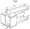
- Figure 8 shows a modified mechanism which is not subject to this limitation.
- the intermediate plate 38 of Figure 2 is replaced by an intermediate plate 86 having holes 88 and 90 for receiving the spring ends 56 and 76 of Figure 2.
- the yoke 26 of Figure 2 is replaced by upper and lower long links 92 and 94 which are connected to the intermediate plate 86 by respective pivot pins 96 and 98.
- the clevis 42 of Figure 2 is replaced by upper and lower long links 100 and 102 which are connected to the intermediate plate 86 by respective pivot pins 104 and 106.
Landscapes
- Engineering & Computer Science (AREA)
- Multimedia (AREA)
- Mechanical Engineering (AREA)
- Rear-View Mirror Devices That Are Mounted On The Exterior Of The Vehicle (AREA)
Applications Claiming Priority (2)
| Application Number | Priority Date | Filing Date | Title |
|---|---|---|---|
| GB9720912 | 1997-10-03 | ||
| GBGB9720912.6A GB9720912D0 (en) | 1997-10-03 | 1997-10-03 | Vehicle exterior mirror |
Publications (2)
| Publication Number | Publication Date |
|---|---|
| EP0906852A2 true EP0906852A2 (de) | 1999-04-07 |
| EP0906852A3 EP0906852A3 (de) | 2000-03-01 |
Family
ID=10819940
Family Applications (1)
| Application Number | Title | Priority Date | Filing Date |
|---|---|---|---|
| EP98308107A Withdrawn EP0906852A3 (de) | 1997-10-03 | 1998-10-01 | Aussenrückblickspiegel für Kraftfahrzeug |
Country Status (6)
| Country | Link |
|---|---|
| US (1) | US6010226A (de) |
| EP (1) | EP0906852A3 (de) |
| JP (1) | JPH11157388A (de) |
| KR (1) | KR100572898B1 (de) |
| BR (1) | BR9803818A (de) |
| GB (1) | GB9720912D0 (de) |
Families Citing this family (3)
| Publication number | Priority date | Publication date | Assignee | Title |
|---|---|---|---|---|
| TW486869B (en) * | 1999-12-27 | 2002-05-11 | Sanyo Electric Co | Voltage producing circuit and a display device provided with such voltage producing circuit |
| JP5282050B2 (ja) * | 2010-01-21 | 2013-09-04 | 株式会社日本除雪機製作所 | 重量物運搬車のサイドミラーステー機構 |
| GB201220764D0 (en) * | 2012-11-19 | 2013-01-02 | Agco Int Gmbh | Folding vehicle rear view mirrors |
Citations (3)
| Publication number | Priority date | Publication date | Assignee | Title |
|---|---|---|---|---|
| DE3237289A1 (de) | 1982-10-08 | 1984-04-12 | Reitter & Schefenacker Kg, 7300 Esslingen | Aussenrueckblickspiegel |
| DE3307532A1 (de) | 1983-03-03 | 1984-09-06 | Reitter & Schefenacker Kg, 7300 Esslingen | Halterung fuer einen abklappbaren kraftfahrzeugaussenspiegel |
| US5009362A (en) | 1989-03-23 | 1991-04-23 | Brangle Jr Edward J | Quick-assembled folding carton with reinforced bottom that locks in position |
Family Cites Families (14)
| Publication number | Priority date | Publication date | Assignee | Title |
|---|---|---|---|---|
| IT7853734U1 (it) * | 1978-09-28 | 1980-03-28 | Vitaloni Spa | Specchio retrovisore esterno, particolarmente per autocaravan, veicoli commerciali e simili. |
| JPS606814B2 (ja) * | 1979-04-09 | 1985-02-20 | 株式会社 村上開明堂 | ダイレクトリモコンバツクミラ− |
| DE3120002C2 (de) * | 1981-05-20 | 1986-07-24 | Unitechnic AG, Chur | Außenrückblickspiegel für Fahrzeuge |
| JPS6032147U (ja) * | 1983-08-12 | 1985-03-05 | 株式会社 村上開明堂 | 回避機構付ドアミラ− |
| JPS60215445A (ja) * | 1984-04-10 | 1985-10-28 | Ichikoh Ind Ltd | ドアミラ−の格納機構 |
| JPS60219139A (ja) * | 1984-04-17 | 1985-11-01 | Ichikoh Ind Ltd | ドアミラ− |
| DE3613878C1 (de) * | 1986-04-24 | 1987-07-09 | Daimler Benz Ag | Aussenspiegel fuer Fahrzeuge |
| US4685779A (en) * | 1986-04-28 | 1987-08-11 | Kasos N.V. | Combined forward and rearward viewing mirror assembly for automotive vehicles |
| DE3872866D1 (de) * | 1987-12-18 | 1992-08-20 | Hohe Kg | Klappbarer aussenspiegel fuer ein fahrzeug. |
| GB8810219D0 (en) * | 1988-04-29 | 1988-06-02 | Britax Geco Sa | Exterior mirror for motor vehicle |
| DE3926891C2 (de) * | 1989-08-16 | 1998-02-05 | Bernhard Mittelhaeuser | Aussenrückblickspiegel für Kraftfahrzeuge |
| DE4004686C1 (en) * | 1990-02-15 | 1991-05-16 | Mercedes-Benz Aktiengesellschaft, 7000 Stuttgart, De | Safety mounting for external driving mirror - allows mirror to swing about axes at both front and rear edges, folding back in either direction during crash |
| KR940000043B1 (ko) * | 1991-07-08 | 1994-01-05 | 황명진 | 파워회동장치가 내장된 자동차용 백미러 |
| KR960010641Y1 (ko) * | 1994-10-22 | 1996-12-23 | 주식회사 대성 | 자동차용 사이드미러 |
-
1997
- 1997-10-03 GB GBGB9720912.6A patent/GB9720912D0/en not_active Ceased
-
1998
- 1998-09-30 BR BR9803818-4A patent/BR9803818A/pt not_active Application Discontinuation
- 1998-09-30 KR KR1019980040812A patent/KR100572898B1/ko not_active Expired - Lifetime
- 1998-10-01 EP EP98308107A patent/EP0906852A3/de not_active Withdrawn
- 1998-10-02 JP JP10280755A patent/JPH11157388A/ja active Pending
- 1998-10-05 US US09/166,372 patent/US6010226A/en not_active Expired - Lifetime
Patent Citations (3)
| Publication number | Priority date | Publication date | Assignee | Title |
|---|---|---|---|---|
| DE3237289A1 (de) | 1982-10-08 | 1984-04-12 | Reitter & Schefenacker Kg, 7300 Esslingen | Aussenrueckblickspiegel |
| DE3307532A1 (de) | 1983-03-03 | 1984-09-06 | Reitter & Schefenacker Kg, 7300 Esslingen | Halterung fuer einen abklappbaren kraftfahrzeugaussenspiegel |
| US5009362A (en) | 1989-03-23 | 1991-04-23 | Brangle Jr Edward J | Quick-assembled folding carton with reinforced bottom that locks in position |
Also Published As
| Publication number | Publication date |
|---|---|
| BR9803818A (pt) | 1999-11-16 |
| JPH11157388A (ja) | 1999-06-15 |
| US6010226A (en) | 2000-01-04 |
| EP0906852A3 (de) | 2000-03-01 |
| KR100572898B1 (ko) | 2007-07-09 |
| KR19990036714A (ko) | 1999-05-25 |
| GB9720912D0 (en) | 1997-12-03 |
Similar Documents
| Publication | Publication Date | Title |
|---|---|---|
| US4740066A (en) | Exterior rear view mirrors for vehicles | |
| JP5226104B2 (ja) | ワイパーブレードを連結する手段を備える自動車用ワイパー | |
| EP0873461B1 (de) | Schwenkvorrichtung für kraftfahrzeugtüren | |
| US5327288A (en) | Reduced vibration day/night rearview mirror assembly | |
| US20080034552A1 (en) | Hinge for a motor vehicle | |
| FR2671762A1 (fr) | Systeme de suspension avec ressort a lame transversal. | |
| EP1731368A1 (de) | Konisches Gelenk für einen Fahrzeugrückspiegel | |
| US7669277B2 (en) | Connector for securing wiper blade to wiper arm and wiper blade assembly | |
| EP0290232A2 (de) | Einklappbare Spiegel | |
| EP0174098B1 (de) | Aussen-Rückspiegel für Kraftfahrzeuge | |
| EP0906852A2 (de) | Aussenrückblickspiegel für Kraftfahrzeug | |
| US4957265A (en) | Foldable outside rear-view mirror for vehicles | |
| JPH03208738A (ja) | 車両用ヘッドランプの取付構造 | |
| US4836490A (en) | Exterior mirror for a vehicle | |
| US7744229B2 (en) | Outside rear view mirror for vehicles, preferably for motor vehicles | |
| JPS6246742A (ja) | パンタグラフ型ワイパ−・ア−ム用連結装置 | |
| US4697297A (en) | Windshield wiper | |
| US6611184B2 (en) | Relay | |
| EP0770525A2 (de) | Antriebsarme für Scheibenwischer | |
| US4872636A (en) | Exterior mirror for a vehicle | |
| JPH0134907Y2 (de) | ||
| KR960010641Y1 (ko) | 자동차용 사이드미러 | |
| JPH058203Y2 (de) | ||
| AU711890B2 (en) | Improvements in drive arm assemblies for wiper blades | |
| EP0049984B1 (de) | Windabweiser für Fahrzeuge |
Legal Events
| Date | Code | Title | Description |
|---|---|---|---|
| PUAI | Public reference made under article 153(3) epc to a published international application that has entered the european phase |
Free format text: ORIGINAL CODE: 0009012 |
|
| AK | Designated contracting states |
Kind code of ref document: A2 Designated state(s): DE FR GB |
|
| AX | Request for extension of the european patent |
Free format text: AL;LT;LV;MK;RO;SI |
|
| PUAL | Search report despatched |
Free format text: ORIGINAL CODE: 0009013 |
|
| AK | Designated contracting states |
Kind code of ref document: A3 Designated state(s): AT BE CH CY DE DK ES FI FR GB GR IE IT LI LU MC NL PT SE |
|
| AX | Request for extension of the european patent |
Free format text: AL;LT;LV;MK;RO;SI |
|
| 17P | Request for examination filed |
Effective date: 20000721 |
|
| AKX | Designation fees paid |
Free format text: DE FR GB |
|
| 17Q | First examination report despatched |
Effective date: 20011218 |
|
| RAP1 | Party data changed (applicant data changed or rights of an application transferred) |
Owner name: SCHEFENACKER VISION SYSTEMS AUSTRALIA PTY LTD |
|
| STAA | Information on the status of an ep patent application or granted ep patent |
Free format text: STATUS: THE APPLICATION IS DEEMED TO BE WITHDRAWN |
|
| 18D | Application deemed to be withdrawn |
Effective date: 20020430 |