EP0906829A2 - Imprimante à jet d'encre avec système de poste de maintenance - Google Patents
Imprimante à jet d'encre avec système de poste de maintenance Download PDFInfo
- Publication number
- EP0906829A2 EP0906829A2 EP98118356A EP98118356A EP0906829A2 EP 0906829 A2 EP0906829 A2 EP 0906829A2 EP 98118356 A EP98118356 A EP 98118356A EP 98118356 A EP98118356 A EP 98118356A EP 0906829 A2 EP0906829 A2 EP 0906829A2
- Authority
- EP
- European Patent Office
- Prior art keywords
- members
- camshaft
- wiping
- assembly station
- maintenance assembly
- Prior art date
- Legal status (The legal status is an assumption and is not a legal conclusion. Google has not performed a legal analysis and makes no representation as to the accuracy of the status listed.)
- Granted
Links
- 238000012423 maintenance Methods 0.000 title claims abstract description 44
- 238000007789 sealing Methods 0.000 claims abstract description 27
- 238000004140 cleaning Methods 0.000 claims abstract description 18
- 230000000694 effects Effects 0.000 claims abstract description 12
- 230000000712 assembly Effects 0.000 claims abstract description 7
- 238000000429 assembly Methods 0.000 claims abstract description 7
- 229920002994 synthetic fiber Polymers 0.000 claims description 3
- 230000003213 activating effect Effects 0.000 claims description 2
- 230000007704 transition Effects 0.000 claims description 2
- 238000001035 drying Methods 0.000 description 3
- 238000007639 printing Methods 0.000 description 3
- 230000008901 benefit Effects 0.000 description 2
- 230000010354 integration Effects 0.000 description 2
- 238000010276 construction Methods 0.000 description 1
- 230000008878 coupling Effects 0.000 description 1
- 238000010168 coupling process Methods 0.000 description 1
- 238000005859 coupling reaction Methods 0.000 description 1
- 238000001514 detection method Methods 0.000 description 1
- 238000006073 displacement reaction Methods 0.000 description 1
- 239000013536 elastomeric material Substances 0.000 description 1
- 230000002349 favourable effect Effects 0.000 description 1
- 238000001746 injection moulding Methods 0.000 description 1
- 230000007246 mechanism Effects 0.000 description 1
- 230000037452 priming Effects 0.000 description 1
- 230000001737 promoting effect Effects 0.000 description 1
Images


Classifications
-
- B—PERFORMING OPERATIONS; TRANSPORTING
- B41—PRINTING; LINING MACHINES; TYPEWRITERS; STAMPS
- B41J—TYPEWRITERS; SELECTIVE PRINTING MECHANISMS, i.e. MECHANISMS PRINTING OTHERWISE THAN FROM A FORME; CORRECTION OF TYPOGRAPHICAL ERRORS
- B41J2/00—Typewriters or selective printing mechanisms characterised by the printing or marking process for which they are designed
- B41J2/005—Typewriters or selective printing mechanisms characterised by the printing or marking process for which they are designed characterised by bringing liquid or particles selectively into contact with a printing material
- B41J2/01—Ink jet
- B41J2/135—Nozzles
- B41J2/165—Prevention or detection of nozzle clogging, e.g. cleaning, capping or moistening for nozzles
- B41J2/16517—Cleaning of print head nozzles
- B41J2/16535—Cleaning of print head nozzles using wiping constructions
- B41J2/16544—Constructions for the positioning of wipers
- B41J2/16547—Constructions for the positioning of wipers the wipers and caps or spittoons being on the same movable support
Definitions
- This invention relates to an ink-jet printer comprising a chassis, a movable carriage bearing at least one printhead and suitable for being moved according to a direction of movement and a maintenance assembly station comprising at least one sealing member intended to be applied against the printhead and a wiping member for wiping the ink off the printhead.
- ink-jet printers it is common practice to protect the ink emission nozzles of the printhead, when they are in the idle position for a considerable length of time between printing periods, in order to prevent the ink from drying and clogging the nozzles.
- a cap is applied against the front plate of the nozzles and this maintains a certain degree of humidity.
- U.S. patent no. 5,155,497 describes a maintenance assembly station for a printer with interchangeable printheads.
- This station comprises a support rotating at 180° about an axis parallel to the direction of movement of the carriage and upon which two caps are mounted in opposite positions by means of two slides which can be moved longitudinally along this direction of movement of the movable carriage.
- the rotating support Upon detection of the type of printhead mounted on the carriage, the rotating support performs a rotation to put the slide and the cap that correspond to the head in position, and the carriage then moves the slide longitudinally in order to apply the cap against the nozzle-carrying plate.
- This maintenance assembly station is composed of a large number of parts and is difficult to construct. What is more, it cannot be integrated in existing printers and is not applicable on printers having two or more printheads mounted on the carriage at the same time.
- the object of this invention is to produce a printer having a maintenance assembly station that is very easy to build, works reliably, has a low cost price, is suitable for integration in existing printers and applicable on printers with one, two or more printheads.
- the invention is characterized to this end by the fact that the maintenance assembly station comprises a camshaft fitted rotatingly with its axis oriented substantially parallel to the direction of movement and arranged so as to activate all the moving members of the maintenance station.
- a printer having a maintenance assembly station that is very easy to build and thoroughly suited to the functions to be accomplished, that works precisely and reliably, and that has a low cost price.
- the maintenance assembly station is suitable for integration without difficulty in existing printers and can be applied on printers with one, two or more printheads due to the fact that numerous movable members can be activated with a complex, precise timing mechanism.
- the maintenance assembly station comprises one or more sealing members, one or more wiping members, one or more cleaning members intended for removing the ink accumulated on the wiping members and at least one suction member connected to the sealing members to produce a sucking effect therein, all these members being fitted on the said module one after the other in the said direction and each activated by elements forming a cam integral with the said shaft.
- a maintenance assembly station is obtained that is particularly effective and of reliable operation, protecting one or more printheads simultaneously.
- a preferred embodiment is characterized by the fact that the maintenance assembly station comprises a module provided with a support constituting the body of the module wherein the said camshaft is fitted with an orientation parallel to the said direction of movement in a substantially central position, the said sealing, wiping and cleaning members each comprising a part fitted movably on the support, having a central aperture for the passage of the said camshaft and a portion intended for co-operating with the camshaft.
- the maintenance assembly station thus possesses a particularly compact build, with low overall dimensions, while at the same time permitting precision control of the maintenance functions.
- the active members of the camshaft are arranged so that a working cycle of the maintenance assembly station comprises the following steps:
- the camshaft is made as one piece of a moulded, synthetic material.
- the printer illustrated in figure 1 comprises a carriage 10 provided with two printheads 11, 12. This carriage is fitted slidingly on a shaft 14 affixed to the chassis 15 of the printer and moves backwards and forwards along a document to be printed according to a direction 16.
- the printer possesses a maintenance assembly station 18, disposed to one side outside the printing zone. This station consists of a compact module serving the two printheads, ensuring that they are cleaned, and also that they are sealed when in the rest position in order to prevent the ink from drying in the nozzles of the printheads and the nozzles from becoming clogged.
- the maintenance assembly station 18 comprises two sealing members 20 in the form of caps 21 intended for covering the front part of the printheads, two wiping members 22 each comprising a flexible bib 23 intended for coming into contact with the front part of the heads and their nozzles in order to wipe the latter, two cleaning members 24 for the bibs 23 having a scraper 25 arranged so as to eliminate the ink accumulated on the bibs 23 and a suction member 26 intended for exercising a depression and a sucking effect on the nozzles of the printheads. All these members 20, 22, 24 and 26 are fitted on a support 30 constituting the body of the maintenance assembly station module.
- camshaft 31 connected by means of a friction coupling 32 to a drive motor not depicted.
- the camshaft 31 is fitted rotatingly on the support 30 of the module and arranged in an orientation parallel to the direction 16 of movement of the carriage 10.
- the shaft 31 and its seven cams are made as a single piece, for instance by the injection moulding of a synthetic material.
- the maintenance assembly station 18 thus possesses two maintenance assemblies 27, 28 each consisting of a wiping member 22, a cleaning member 24 and a sealing member 20 fitted one after the other in the said direction 16, the suction member 26 being arranged between the two assemblies 27, 28.
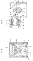
- Each of the sealing members 20 (figure 4) comprises a sliding part 35 fitted in grooves 36 in the support 30.
- This sliding part 35 in its upper part, has a wall 37 intended for receiving the cap 21, made of a flexible elastomeric material and arranged to be applied tightly against the front part of one of the two printheads 11, 12.
- the wall 37 with the cap 21 forms a chamber 39 having an outgoing end 40 connected by a flexible pipe 41 or 42 (fig. 2,3) to the suction member 26.
- An intermediate portion of the sliding part 35 is provided with a central aperture 44, allowing the camshaft 31 to pass.
- An intermediate edge 45 co-operates with the cam 55 of the shaft 31 and a spring 43 is arranged so as to urge the intermediate edge 45 against the cam 55.
- the sliding part 35 is in the lower position.
- the sliding part 35 is in the upper position, wherein the flexible cap 21 comes to rest against the face of the nozzles of one of the printheads 11, 12, which is thus sealed in order to prevent the ink from drying when the printer is in the idle position.
- the wiping members 22 comprise a sliding part 46 arranged in grooves 47 in the support 30.
- the flexible bib 23 is affixed to the upper portion of this sliding part, while a spring 74 is arranged so as to urge an intermediate edge 49 of this sliding part 46 against a cam 48 of the shaft 31, which traverses the part 46 thanks to a central aperture 56.
- the wiping member 22 In the position illustrated, the wiping member 22 is in its upper position and the flexible bib 23 sweeps the front face of the printhead and the nozzles when the latter moves past in front of the wiping member.
- the cleaning members 24 depicted in figure 6 comprise a pivoting part 50, provided with two pivots 51 engaging in apertures made in the support 30.
- the upper portion of this pivoting part is chamfered in order to constitute the scraper 25.
- the pivoting part 50 is provided with a finger 52 engaging in a groove 53 in the shape of a cam of the shaft 31 and a spring 54 is arranged so as to urge this finger 52 against one of the faces of this groove in order to define a very precise position of the pivoting part 50.
- the camshaft 31 traverses the pivoting part 50 thanks to a central aperture 73.
- the scraper 25 is disengaged from the bib 22. Following a rotation of about 90° in a right-handed direction, this scraper 25 is moved forward and gathers the ink deposited on the bib 23 while the latter is moved downwardly. The ink flows downwards thanks to the corrugated part of the scraper 25.
- the sealing 20, wiping 22 and cleaning 24 members thus each consist of a part fitted movably on the support 30, having a central aperture 44, 56, 73 allowing the said camshaft 31 to pass and a portion 45, 49, 52 intended for co-operating with the camshaft 31.
- the suction member or pump 26 comprises a cylinder 57 attached by three catches 58 to the support 30 and a piston 59 slidingly fitted in the cylinder 57 in opposition to a spring 60 housed in a chamber 61 of the cylinder.
- This chamber communicates through ends 62 with the flexible pipes 41, 42 connected to the sealing members 20.
- the piston 59 is provided with two activating pins 63, 64.
- the first pin 63 is shorter and is arranged between two branches 65 of the second pin 64.
- This first pin 63 comprises a step 66 suitable for co-operating with a lip 67 of the camshaft 31.
- the second pin 64 is longer and flexible and comprises an end part 68 connected to the two branches 65 and is provided with two teeth 69, 70.
- the first, outer tooth 69 co-operates with the wall of the support 30 to maintain the piston 59 in this position in opposition to the effect of the spring 60.
- the piston 59 is driven to the right by the lip 67 in abutment against the step 66.
- the second, resilient pin 64 can then, by its second tooth 70, fasten onto the support 30, and the pump is then in the armed position.
- the suction member 26 can thus exert a depression on the nozzles of the printheads, which leads to there being only a small amount of ink on the face of the nozzles, permitting a priming of the latter and promoting the cleaning of the front face of the printheads 11, 12 and of the nozzles during the passage over the bibs 23.
- the active elements of the camshaft 31 are arranged in such a way that the complete operating cycle of the maintenance assembly stations controlled by the camshaft 31 takes place as follows:
- the maintenance assembly station could be envisaged for one or three or more printheads borne by the carriage and will then comprise one or three or more maintenance assemblies.
- the cams provided on the shaft 31 could be adapted differently, for example, to produce a wiping on the outbound and return movement of the carriage.
- the scraper could then be adapted to treat two faces of the bibs.
Landscapes
- Ink Jet (AREA)
Applications Claiming Priority (3)
| Application Number | Priority Date | Filing Date | Title |
|---|---|---|---|
| CH02307/97A CH691766A5 (fr) | 1997-10-02 | 1997-10-02 | Imprimante à jet d'encre avec station de maintenance. |
| CH2307/97 | 1997-10-02 | ||
| CH230797 | 1997-10-02 |
Publications (3)
| Publication Number | Publication Date |
|---|---|
| EP0906829A2 true EP0906829A2 (fr) | 1999-04-07 |
| EP0906829A3 EP0906829A3 (fr) | 1999-07-21 |
| EP0906829B1 EP0906829B1 (fr) | 2003-11-12 |
Family
ID=4230746
Family Applications (1)
| Application Number | Title | Priority Date | Filing Date |
|---|---|---|---|
| EP98118356A Expired - Lifetime EP0906829B1 (fr) | 1997-10-02 | 1998-09-28 | Imprimante à jet d'encre avec système de poste de maintenance |
Country Status (4)
| Country | Link |
|---|---|
| US (1) | US6139129A (fr) |
| EP (1) | EP0906829B1 (fr) |
| CH (1) | CH691766A5 (fr) |
| DE (1) | DE69819650T2 (fr) |
Families Citing this family (9)
| Publication number | Priority date | Publication date | Assignee | Title |
|---|---|---|---|---|
| US6402293B1 (en) * | 2000-06-16 | 2002-06-11 | Xerox Corp. | Vacuum accumulator and ink manifold |
| US6398339B1 (en) * | 2000-06-16 | 2002-06-04 | Xerox Corp. | Time and drive systems for a multifunction ink jet printer maintenance station |
| US6416161B1 (en) * | 2000-06-16 | 2002-07-09 | Xerox Corporation | Wiper blade mechanism for ink jet printers |
| US6398338B1 (en) * | 2000-06-16 | 2002-06-04 | Xerox Corporation | Cam-actuated lever capping arm |
| US6592200B2 (en) * | 2001-10-30 | 2003-07-15 | Hewlett-Packard Development Company, L.P. | Integrated print module and servicing assembly |
| US6595619B2 (en) * | 2001-10-30 | 2003-07-22 | Hewlett-Packard Development Company, L.P. | Printing mechanism service station for a printbar assembly |
| US6773088B2 (en) * | 2002-11-15 | 2004-08-10 | Lexmark International, Inc. | Double lipped printhead maintenance cap |
| US6817695B1 (en) | 2003-06-03 | 2004-11-16 | Lexmark International, Inc. | Printhead capping assembly |
| US7021741B2 (en) * | 2003-11-21 | 2006-04-04 | Lexmark International, Inc. | Printhead cap assembly for an ink jet printer |
Citations (1)
| Publication number | Priority date | Publication date | Assignee | Title |
|---|---|---|---|---|
| US5155497A (en) | 1991-07-30 | 1992-10-13 | Hewlett-Packard Company | Service station for ink-jet printer |
Family Cites Families (8)
| Publication number | Priority date | Publication date | Assignee | Title |
|---|---|---|---|---|
| KR940010881B1 (ko) * | 1988-10-07 | 1994-11-19 | 캐논 가부시끼가이샤 | 기록장치 |
| JPH0326546U (fr) * | 1989-07-25 | 1991-03-18 | ||
| EP0480302B1 (fr) * | 1990-10-03 | 1996-05-01 | Canon Kabushiki Kaisha | Appareil d'enregistrement à jet d'encre |
| JP2872431B2 (ja) * | 1991-04-22 | 1999-03-17 | キヤノン株式会社 | インクジェット記録装置 |
| US5339102A (en) * | 1992-11-12 | 1994-08-16 | Xerox Corporation | Capping carriage for ink jet printer maintenance station |
| US5712668A (en) * | 1994-03-25 | 1998-01-27 | Hewlett-Packard Company | Rotary Multi-ridge capping system for inkjet printheads |
| KR200151933Y1 (ko) * | 1996-04-08 | 1999-07-15 | 윤종용 | 잉크젯프린터의 서어비스 스테이션장치 |
| JP3704820B2 (ja) * | 1996-07-16 | 2005-10-12 | ブラザー工業株式会社 | インクジェットヘッドのキャップ手段 |
-
1997
- 1997-10-02 CH CH02307/97A patent/CH691766A5/fr not_active IP Right Cessation
-
1998
- 1998-09-28 DE DE69819650T patent/DE69819650T2/de not_active Expired - Lifetime
- 1998-09-28 EP EP98118356A patent/EP0906829B1/fr not_active Expired - Lifetime
- 1998-09-29 US US09/162,505 patent/US6139129A/en not_active Expired - Lifetime
Patent Citations (1)
| Publication number | Priority date | Publication date | Assignee | Title |
|---|---|---|---|---|
| US5155497A (en) | 1991-07-30 | 1992-10-13 | Hewlett-Packard Company | Service station for ink-jet printer |
Also Published As
| Publication number | Publication date |
|---|---|
| DE69819650D1 (de) | 2003-12-18 |
| EP0906829B1 (fr) | 2003-11-12 |
| DE69819650T2 (de) | 2004-09-30 |
| CH691766A5 (fr) | 2001-10-15 |
| EP0906829A3 (fr) | 1999-07-21 |
| US6139129A (en) | 2000-10-31 |
Similar Documents
| Publication | Publication Date | Title |
|---|---|---|
| JP4939620B2 (ja) | サービスステーションおよびインクジェットプリンタ | |
| JP2626805B2 (ja) | インクジェット記録装置 | |
| JP3595370B2 (ja) | インクジェットプリンタ用プリンタヘッド拭き取り構造 | |
| EP1870241B1 (fr) | Appareil de formation d'images et son procédé de commande | |
| DE69502654T2 (de) | Modulare Wischeinheit für Tintenstrahldrucker | |
| JP2005138317A (ja) | 吐出回復装置及びインクジェット記録装置 | |
| US6139129A (en) | Ink-jet printer having a maintenance station assembly | |
| EP0730965B1 (fr) | Technique de nettoyage à mouvement rectiligne pour une tête d'impression à jet d'encre | |
| JP5455575B2 (ja) | 記録装置 | |
| JP4217435B2 (ja) | インクジェット記録装置 | |
| US6702423B2 (en) | Cleaning device for inkjet printing head, cleaning method for inkjet printing head, inkjet recording apparatus, and wiper | |
| JPH07276654A (ja) | インクジェットプリンタ用の拭き取り構造 | |
| US20070115318A1 (en) | Ink Jet Recording Apparatus | |
| JP2720060B2 (ja) | 回復方法 | |
| JP2618007B2 (ja) | インクジェット記録装置 | |
| US7703880B2 (en) | Inkjet recording apparatus | |
| JPH09141884A (ja) | インクジェットプリンタ | |
| JP2014043026A (ja) | 記録装置 | |
| JP5028072B2 (ja) | インクジェット画像記録装置 | |
| JP2002240308A (ja) | 記録ヘッドユニット及びインクジェット記録装置 | |
| JPH1029314A (ja) | インクジェットヘッドのキャップ手段 | |
| JP2001347679A (ja) | インクジェット式記録装置 | |
| JPH07223320A (ja) | インクジェットプリンタ | |
| EP0960735B1 (fr) | Appareil et méthode de netoyage pour tête d'impression à jets d'encre | |
| JPH1029315A (ja) | インクジェットヘッドのクリーニング装置 |
Legal Events
| Date | Code | Title | Description |
|---|---|---|---|
| PUAI | Public reference made under article 153(3) epc to a published international application that has entered the european phase |
Free format text: ORIGINAL CODE: 0009012 |
|
| AK | Designated contracting states |
Kind code of ref document: A2 Designated state(s): DE FR GB IT |
|
| AX | Request for extension of the european patent |
Free format text: AL;LT;LV;MK;RO;SI |
|
| PUAL | Search report despatched |
Free format text: ORIGINAL CODE: 0009013 |
|
| AK | Designated contracting states |
Kind code of ref document: A3 Designated state(s): AT BE CH CY DE DK ES FI FR GB GR IE IT LI LU MC NL PT SE |
|
| AX | Request for extension of the european patent |
Free format text: AL;LT;LV;MK;RO;SI |
|
| 17P | Request for examination filed |
Effective date: 19991214 |
|
| AKX | Designation fees paid |
Free format text: AT BE CH DE DK ES FI FR GB GR IE IT LI LU MC NL PT SE |
|
| RBV | Designated contracting states (corrected) |
Designated state(s): DE FR GB IT |
|
| RAP1 | Party data changed (applicant data changed or rights of an application transferred) |
Owner name: OLIVETTI TECNOST S.P.A. |
|
| 17Q | First examination report despatched |
Effective date: 20020514 |
|
| GRAH | Despatch of communication of intention to grant a patent |
Free format text: ORIGINAL CODE: EPIDOS IGRA |
|
| GRAS | Grant fee paid |
Free format text: ORIGINAL CODE: EPIDOSNIGR3 |
|
| GRAA | (expected) grant |
Free format text: ORIGINAL CODE: 0009210 |
|
| AK | Designated contracting states |
Kind code of ref document: B1 Designated state(s): DE FR GB IT |
|
| REG | Reference to a national code |
Ref country code: GB Ref legal event code: FG4D |
|
| REF | Corresponds to: |
Ref document number: 69819650 Country of ref document: DE Date of ref document: 20031218 Kind code of ref document: P |
|
| ET | Fr: translation filed | ||
| PLBE | No opposition filed within time limit |
Free format text: ORIGINAL CODE: 0009261 |
|
| STAA | Information on the status of an ep patent application or granted ep patent |
Free format text: STATUS: NO OPPOSITION FILED WITHIN TIME LIMIT |
|
| 26N | No opposition filed |
Effective date: 20040813 |
|
| PGFP | Annual fee paid to national office [announced via postgrant information from national office to epo] |
Ref country code: GB Payment date: 20140929 Year of fee payment: 17 |
|
| PGFP | Annual fee paid to national office [announced via postgrant information from national office to epo] |
Ref country code: DE Payment date: 20140929 Year of fee payment: 17 |
|
| REG | Reference to a national code |
Ref country code: DE Ref legal event code: R082 Ref document number: 69819650 Country of ref document: DE Representative=s name: WEICKMANN & WEICKMANN PATENTANWAELTE - RECHTSA, DE Ref country code: DE Ref legal event code: R082 Ref document number: 69819650 Country of ref document: DE Representative=s name: PATENTANWAELTE WEICKMANN & WEICKMANN, DE |
|
| REG | Reference to a national code |
Ref country code: FR Ref legal event code: PLFP Year of fee payment: 18 |
|
| PGFP | Annual fee paid to national office [announced via postgrant information from national office to epo] |
Ref country code: FR Payment date: 20150917 Year of fee payment: 18 |
|
| PGFP | Annual fee paid to national office [announced via postgrant information from national office to epo] |
Ref country code: IT Payment date: 20150923 Year of fee payment: 18 |
|
| REG | Reference to a national code |
Ref country code: DE Ref legal event code: R119 Ref document number: 69819650 Country of ref document: DE |
|
| GBPC | Gb: european patent ceased through non-payment of renewal fee |
Effective date: 20150928 |
|
| PG25 | Lapsed in a contracting state [announced via postgrant information from national office to epo] |
Ref country code: GB Free format text: LAPSE BECAUSE OF NON-PAYMENT OF DUE FEES Effective date: 20150928 Ref country code: DE Free format text: LAPSE BECAUSE OF NON-PAYMENT OF DUE FEES Effective date: 20160401 |
|
| REG | Reference to a national code |
Ref country code: FR Ref legal event code: ST Effective date: 20170531 |
|
| PG25 | Lapsed in a contracting state [announced via postgrant information from national office to epo] |
Ref country code: FR Free format text: LAPSE BECAUSE OF NON-PAYMENT OF DUE FEES Effective date: 20160930 |
|
| PG25 | Lapsed in a contracting state [announced via postgrant information from national office to epo] |
Ref country code: IT Free format text: LAPSE BECAUSE OF NON-PAYMENT OF DUE FEES Effective date: 20160928 |