EP0906829B1 - Imprimante à jet d'encre avec système de poste de maintenance - Google Patents
Imprimante à jet d'encre avec système de poste de maintenance Download PDFInfo
- Publication number
- EP0906829B1 EP0906829B1 EP98118356A EP98118356A EP0906829B1 EP 0906829 B1 EP0906829 B1 EP 0906829B1 EP 98118356 A EP98118356 A EP 98118356A EP 98118356 A EP98118356 A EP 98118356A EP 0906829 B1 EP0906829 B1 EP 0906829B1
- Authority
- EP
- European Patent Office
- Prior art keywords
- members
- camshaft
- wiping
- assembly station
- fitted
- Prior art date
- Legal status (The legal status is an assumption and is not a legal conclusion. Google has not performed a legal analysis and makes no representation as to the accuracy of the status listed.)
- Expired - Lifetime
Links
- 238000012423 maintenance Methods 0.000 title claims description 40
- 238000007789 sealing Methods 0.000 claims description 25
- 238000004140 cleaning Methods 0.000 claims description 17
- 230000000694 effects Effects 0.000 claims description 12
- 230000000712 assembly Effects 0.000 claims description 5
- 238000000429 assembly Methods 0.000 claims description 5
- 230000003213 activating effect Effects 0.000 claims description 3
- 229920002994 synthetic fiber Polymers 0.000 claims description 3
- 230000007704 transition Effects 0.000 claims description 2
- 238000001035 drying Methods 0.000 description 3
- 238000007639 printing Methods 0.000 description 3
- 230000008901 benefit Effects 0.000 description 2
- 230000010354 integration Effects 0.000 description 2
- 238000010276 construction Methods 0.000 description 1
- 230000008878 coupling Effects 0.000 description 1
- 238000010168 coupling process Methods 0.000 description 1
- 238000005859 coupling reaction Methods 0.000 description 1
- 238000001514 detection method Methods 0.000 description 1
- 238000006073 displacement reaction Methods 0.000 description 1
- 239000013536 elastomeric material Substances 0.000 description 1
- 230000002349 favourable effect Effects 0.000 description 1
- 238000001746 injection moulding Methods 0.000 description 1
- 230000007246 mechanism Effects 0.000 description 1
- 230000037452 priming Effects 0.000 description 1
- 230000001737 promoting effect Effects 0.000 description 1
Images


Classifications
-
- B—PERFORMING OPERATIONS; TRANSPORTING
- B41—PRINTING; LINING MACHINES; TYPEWRITERS; STAMPS
- B41J—TYPEWRITERS; SELECTIVE PRINTING MECHANISMS, i.e. MECHANISMS PRINTING OTHERWISE THAN FROM A FORME; CORRECTION OF TYPOGRAPHICAL ERRORS
- B41J2/00—Typewriters or selective printing mechanisms characterised by the printing or marking process for which they are designed
- B41J2/005—Typewriters or selective printing mechanisms characterised by the printing or marking process for which they are designed characterised by bringing liquid or particles selectively into contact with a printing material
- B41J2/01—Ink jet
- B41J2/135—Nozzles
- B41J2/165—Prevention or detection of nozzle clogging, e.g. cleaning, capping or moistening for nozzles
- B41J2/16517—Cleaning of print head nozzles
- B41J2/16535—Cleaning of print head nozzles using wiping constructions
- B41J2/16544—Constructions for the positioning of wipers
- B41J2/16547—Constructions for the positioning of wipers the wipers and caps or spittoons being on the same movable support
Definitions
- a cap is applied against the front plate of the nozzles and this maintains a certain degree of humidity.
- a maintaining assembly station with a camshaft for an ink-jet printer having more heads is known from EP-A-0 410 691.
- the station comprises, as movable members, four caps and four groups of wiping blades and associated cap arm and wiper support mounted transversely to the heads.
- the camshaft actuates the caps and the blades by means of two adjacent cams and cam followers connected to the cap arm and the wiper support and pivotable around independent axes parallel to the axis of the camshaft.
- This maintenance assembly station does not relate to components other than the caps and the wiping blades. Further its structure is rather cumbersome and not adapted to easily integrate other functional components of the station.
- the object of this invention is to produce a printer having a maintenance assembly station that is very easy to build, works reliably, has a low cost price, is suitable for integration in existing printers and applicable on printers with one, two or more printheads.
- the invention is characterized to this end by the fact that said maintenance assembly station further comprises at least one suction member connected to the sealing members to produce a sucking effect therein, and wherein the camshaft is characterizing part of claim 1.
- a printer having a maintenance assembly station that is very easy to build and thoroughly suited to the functions to be accomplished, that works precisely and reliably, and that has a low cost price.
- the maintenance assembly station is suitable for integration without difficulty in existing printers and can be applied on printers with one, two or more printheads due to the fact that numerous movable members can be activated with a complex, precise timing mechanism.
- a preferred embodiment is characterized by the fact that the maintenance assembly station comprises a module provided with a support constituting the body of the module wherein the said camshaft is fitted with an orientation parallel to the said direction of movement in a substantially central position, the said sealing, wiping and cleaning members each comprising a part fitted movably on the support, having a central aperture for the passage of the said camshaft and a portion intended for co-operating with the camshaft.
- the maintenance assembly station thus possesses a particularly compact build, with low overall dimensions, while at the same time permitting precision control of the maintenance functions.
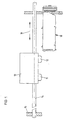
- the maintenance assembly station 18 comprises two sealing members 20 in the form of caps 21 intended for covering the front part of the printheads, two wiping members 22 each comprising a flexible bib 23 intended for coming into contact with the front part of the heads and their nozzles in order to wipe the latter, two cleaning members 24 for the bibs 23 having a scraper 25 arranged so as to eliminate the ink accumulated on the bibs 23 and a suction member 26 intended for exercising a depression and a sucking effect on the nozzles of the printheads. All these members 20, 22, 24 and 26 are fitted on a support 30 constituting the body of the maintenance assembly station module.
- camshaft 31 connected by means of a friction coupling 32 to a drive motor not depicted.
- the camshaft 31 is fitted rotatingly on the support 30 of the module and arranged in an orientation parallel to the direction 16 of movement of the carriage 10.
- the shaft 31 and its seven cams are made as a single piece, for instance by the injection moulding of a synthetic material.
Landscapes
- Ink Jet (AREA)
Claims (10)
- Imprimante à jet d'encre comprenant un châssis (15), un chariot déplaçable (10) supportant une ou plusieurs tête(s) d'impression (11, 12) et adapté pour être déplacé selon une direction de mouvement (16), et une station d'ensemble de maintenance (18) ayant, comme éléments déplaçables, un ou plusieurs élément(s) d'étanchéité (20) adaptés pour être appliqués contre l'une ou plusieurs tête(s) d'impression (11, 12), et un ou plusieurs élément(s) d'essuyage (22) pour essuyer l'encre sur les têtes d'impression (11, 12), et comprenant un arbre à cames (31) pour activer les éléments d'étanchéité (20) et les éléments d'essuyage (22), ladite imprimante étant caractérisée en ce que
la station d'ensemble de maintenance (18) comprend en outre d'autres éléments déplaçables dont au moins un élément d'aspiration (26) relié aux éléments d'étanchéité (20) pour produire un effet d'aspiration à l'intérieur, et dans laquelletous ces éléments sont ajustés les uns après les autres dans ladite direction (16) et chacun d'entre eux est activé par des éléments formant cames (48, 55, 67, 72) formant partie intégrante dudit arbre à cames (31).ledit arbre à cames (31) est ajusté de manière rotative avec son axe orienté de manière globalement parallèle à la direction de mouvement (16) du chariot et est agencé de manière à activer tous les éléments déplaçables (20, 22, 26) de la station d'ensemble de maintenance, y compris ledit au moins un élément d'aspiration (26) ; et - Imprimante selon la revendication 1, caractérisée en ce que la station d'ensemble de maintenance (18) comprend en outre, comme éléments déplaçables, un ou plusieurs élément(s) de nettoyage (24) destinés à retirer l'encre accumulée sur les éléments d'essuyage (22) et dans laquelle lesdits éléments formant cames comprennent un autre élément formant came (53) formant partie intégrante dudit arbre à cames (31).
- Imprimante selon la revendication 2, caractérisée en ce que la station d'ensemble de maintenance (18) comprend un module muni d'un support (30) constituant le corps du module, dans laquelle ledit arbre à cames (31) est ajusté selon une orientation parallèle à ladite direction de mouvement (16) dans une position essentiellement centrale, lesdits éléments d'étanchéité (20), d'essuyage (22) et de nettoyage (24) comprenant chacun une partie (35, 46, 50) ajustée de manière mobile sur le support (30), ayant une ouverture centrale (44, 56, 73) pour permettre audit arbre à cames (31) de passer, et une partie (45, 49, 52) destinée à coopérer avec l'arbre à cames (31).
- Imprimante selon la revendication 2 ou 3, caractérisée en ce que la station d'ensemble de maintenance (18) comprend deux unités de maintenance (27, 28), consistant chacune en un élément d'essuyage (22), un élément de nettoyage (24) et un élément d'étanchéité (20) ajustés l'un après l'autre dans ladite direction (16), l'élément d'aspiration (26) étant agencé entre les deux unités (27, 28).
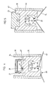
- Imprimante selon l'une des revendications 3 ou 4, caractérisée en ce que l'élément d'étanchéité (20) comprend une partie (35) ajustée de manière coulissante sur ledit support (30) dans une direction perpendiculaire à la direction de mouvement (16), munie d'un couvercle (21) au niveau de son extrémité supérieure fabriqué à partir d'un matériau souple et ayant une ouverture centrale (44) permettant le passage de l'arbre à cames (31) qui coopère avec une partie intermédiaire (45) de cette partie coulissante (35) poussée par un ressort (43) contre l'arbre à cames (31).
- Imprimante selon l'une quelconque des revendications 3 à 5, caractérisée en ce que l'élément d'essuyage (22) comprend une partie (46) ajustée de manière coulissante sur ledit support (30) dans une direction perpendiculaire à la direction de mouvement (16) munie au niveau de son extrémité supérieure d'un rebord souple (23) et ayant une ouverture centrale (56) permettant le passage de l'arbre à cames (31) qui coopère avec une partie intermédiaire (49) de cette partie coulissante (46) poussée par un ressort (74) contre l'arbre à cames (31).
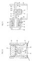
- Imprimante selon l'une quelconque des revendications 3 à 6, caractérisée en ce que l'élément de nettoyage (24) comprend une partie (50) ajustée de manière pivotante par son extrémité inférieure sur ledit support (30), munie au niveau de son extrémité supérieure d'un racloir (25) et ayant une ouverture centrale (73) permettant le passage de l'arbre à cames (31) qui est doté d'une rainure (53) formant une came dans laquelle un doigt (52) de la partie pivotante (50) est engagée.
- Imprimante selon les revendications 3 à 7, caractérisée en ce que l'élément d'aspiration (26) comprend un cylindre (57) fixé sur le support (30) et un piston (59) ajusté de manière coulissante dans une direction perpendiculaire à la direction de mouvement (16), le piston formant partie intégrante d'une tige d'actionnement (63) disposée de manière à coopérer avec une buse (67) de l'arbre à cames pour déplacer le piston (59) d'une position non armée vers une position armée en opposition à l'effet d'un ressort (60), le piston (59) comprenant des moyens de retenue (65, 68, 70) pour retenir le piston (59) en position armée et pouvant coopérer avec une partie (72) de l'arbre à cames (31) pour relâcher le piston (59) afin de créer l'effet d'aspiration dans les éléments d'étanchéité (20).
- Imprimante selon l'une quelconque des revendications 2 à 8, caractérisée en ce que les éléments actifs de l'arbre à cames (31) sont agencés de telle manière qu'un cycle de fonctionnement de la station d'ensemble de maintenance (18) comprend les étapes suivantes :a) position libre : les éléments d'étanchéité (20) sont en position active, l'élément d'aspiration (26) est armé, les éléments d'essuyage (22) et les éléments de nettoyage (24) sont en position inactive ;b) l'élément d'aspiration (26) est activé lors de la transition depuis la position armée vers la position non armée et un effet d'aspiration est créé dans les éléments d'étanchéité (20) ;c) les éléments d'étanchéité (20) sont retirés et les éléments d'essuyage (22) sont mis en position active pour essuyer les têtes d'impression (11, 12) ;d) l'élément d'aspiration (26) est réarmé, les éléments de nettoyage (24) sont mis en position active, tandis que les éléments d'essuyage (22) sont retirés et nettoyés ;e) les éléments de nettoyage (24) sont mis en position inactive ;f) lorsque le chariot (10) est dans une position opposée à la station d'ensemble de maintenance (18), les éléments d'étanchéité (20) sont déplacés en position active afin de revenir à la position libre a).
- Imprimante selon l'une des revendications précédentes, caractérisée en ce que l'arbre à cames (31) est réalisé en une seule pièce en un matériau synthétique moulé.
Applications Claiming Priority (3)
| Application Number | Priority Date | Filing Date | Title |
|---|---|---|---|
| CH230797 | 1997-10-02 | ||
| CH2307/97 | 1997-10-02 | ||
| CH02307/97A CH691766A5 (fr) | 1997-10-02 | 1997-10-02 | Imprimante à jet d'encre avec station de maintenance. |
Publications (3)
| Publication Number | Publication Date |
|---|---|
| EP0906829A2 EP0906829A2 (fr) | 1999-04-07 |
| EP0906829A3 EP0906829A3 (fr) | 1999-07-21 |
| EP0906829B1 true EP0906829B1 (fr) | 2003-11-12 |
Family
ID=4230746
Family Applications (1)
| Application Number | Title | Priority Date | Filing Date |
|---|---|---|---|
| EP98118356A Expired - Lifetime EP0906829B1 (fr) | 1997-10-02 | 1998-09-28 | Imprimante à jet d'encre avec système de poste de maintenance |
Country Status (4)
| Country | Link |
|---|---|
| US (1) | US6139129A (fr) |
| EP (1) | EP0906829B1 (fr) |
| CH (1) | CH691766A5 (fr) |
| DE (1) | DE69819650T2 (fr) |
Families Citing this family (9)
| Publication number | Priority date | Publication date | Assignee | Title |
|---|---|---|---|---|
| US6398338B1 (en) * | 2000-06-16 | 2002-06-04 | Xerox Corporation | Cam-actuated lever capping arm |
| US6416161B1 (en) * | 2000-06-16 | 2002-07-09 | Xerox Corporation | Wiper blade mechanism for ink jet printers |
| US6402293B1 (en) * | 2000-06-16 | 2002-06-11 | Xerox Corp. | Vacuum accumulator and ink manifold |
| US6398339B1 (en) * | 2000-06-16 | 2002-06-04 | Xerox Corp. | Time and drive systems for a multifunction ink jet printer maintenance station |
| US6595619B2 (en) * | 2001-10-30 | 2003-07-22 | Hewlett-Packard Development Company, L.P. | Printing mechanism service station for a printbar assembly |
| US6592200B2 (en) * | 2001-10-30 | 2003-07-15 | Hewlett-Packard Development Company, L.P. | Integrated print module and servicing assembly |
| US6773088B2 (en) * | 2002-11-15 | 2004-08-10 | Lexmark International, Inc. | Double lipped printhead maintenance cap |
| US6817695B1 (en) | 2003-06-03 | 2004-11-16 | Lexmark International, Inc. | Printhead capping assembly |
| US7021741B2 (en) * | 2003-11-21 | 2006-04-04 | Lexmark International, Inc. | Printhead cap assembly for an ink jet printer |
Family Cites Families (9)
| Publication number | Priority date | Publication date | Assignee | Title |
|---|---|---|---|---|
| KR940010881B1 (ko) * | 1988-10-07 | 1994-11-19 | 캐논 가부시끼가이샤 | 기록장치 |
| JPH0326546U (fr) * | 1989-07-25 | 1991-03-18 | ||
| EP0480302B1 (fr) * | 1990-10-03 | 1996-05-01 | Canon Kabushiki Kaisha | Appareil d'enregistrement à jet d'encre |
| JP2872431B2 (ja) * | 1991-04-22 | 1999-03-17 | キヤノン株式会社 | インクジェット記録装置 |
| US5155497A (en) | 1991-07-30 | 1992-10-13 | Hewlett-Packard Company | Service station for ink-jet printer |
| US5339102A (en) * | 1992-11-12 | 1994-08-16 | Xerox Corporation | Capping carriage for ink jet printer maintenance station |
| US5712668A (en) * | 1994-03-25 | 1998-01-27 | Hewlett-Packard Company | Rotary Multi-ridge capping system for inkjet printheads |
| KR200151933Y1 (ko) * | 1996-04-08 | 1999-07-15 | 윤종용 | 잉크젯프린터의 서어비스 스테이션장치 |
| JP3704820B2 (ja) * | 1996-07-16 | 2005-10-12 | ブラザー工業株式会社 | インクジェットヘッドのキャップ手段 |
-
1997
- 1997-10-02 CH CH02307/97A patent/CH691766A5/fr not_active IP Right Cessation
-
1998
- 1998-09-28 DE DE69819650T patent/DE69819650T2/de not_active Expired - Lifetime
- 1998-09-28 EP EP98118356A patent/EP0906829B1/fr not_active Expired - Lifetime
- 1998-09-29 US US09/162,505 patent/US6139129A/en not_active Expired - Lifetime
Also Published As
| Publication number | Publication date |
|---|---|
| EP0906829A2 (fr) | 1999-04-07 |
| EP0906829A3 (fr) | 1999-07-21 |
| DE69819650D1 (de) | 2003-12-18 |
| US6139129A (en) | 2000-10-31 |
| DE69819650T2 (de) | 2004-09-30 |
| CH691766A5 (fr) | 2001-10-15 |
Similar Documents
| Publication | Publication Date | Title |
|---|---|---|
| JP4939620B2 (ja) | サービスステーションおよびインクジェットプリンタ | |
| EP1870241B1 (fr) | Appareil de formation d'images et son procédé de commande | |
| JP5955053B2 (ja) | 記録装置および記録装置の制御方法 | |
| EP0906829B1 (fr) | Imprimante à jet d'encre avec système de poste de maintenance | |
| JP2005138317A (ja) | 吐出回復装置及びインクジェット記録装置 | |
| JP5455575B2 (ja) | 記録装置 | |
| JPH11320915A (ja) | インクジェット記録装置 | |
| US6702423B2 (en) | Cleaning device for inkjet printing head, cleaning method for inkjet printing head, inkjet recording apparatus, and wiper | |
| JP2004042537A (ja) | インクジェット記録装置及び該記録装置の回復機構部 | |
| US7766450B2 (en) | Ink jet recording apparatus | |
| JPH09141884A (ja) | インクジェットプリンタ | |
| JPH0234348A (ja) | インクジェット記録装置 | |
| JP3246983B2 (ja) | 吐出回復装置およびそれを搭載したインクジェット記録装置 | |
| JP3704820B2 (ja) | インクジェットヘッドのキャップ手段 | |
| JP2014043026A (ja) | 記録装置 | |
| JP2002240308A (ja) | 記録ヘッドユニット及びインクジェット記録装置 | |
| JP4174273B2 (ja) | インクジェット記録装置 | |
| JPH07223320A (ja) | インクジェットプリンタ | |
| JP4642184B2 (ja) | インクジェット記録装置 | |
| JP2008126451A (ja) | インクジェット画像記録装置 | |
| JPH1058704A (ja) | インクジェットヘッドの予備吐出用の廃液受容装置 | |
| JP2001347679A (ja) | インクジェット式記録装置 | |
| JP3854705B2 (ja) | インクジェット記録装置 | |
| EP0960735B1 (fr) | Appareil et méthode de netoyage pour tête d'impression à jets d'encre | |
| JP2000015824A (ja) | インクジェット記録装置 |
Legal Events
| Date | Code | Title | Description |
|---|---|---|---|
| PUAI | Public reference made under article 153(3) epc to a published international application that has entered the european phase |
Free format text: ORIGINAL CODE: 0009012 |
|
| AK | Designated contracting states |
Kind code of ref document: A2 Designated state(s): DE FR GB IT |
|
| AX | Request for extension of the european patent |
Free format text: AL;LT;LV;MK;RO;SI |
|
| PUAL | Search report despatched |
Free format text: ORIGINAL CODE: 0009013 |
|
| AK | Designated contracting states |
Kind code of ref document: A3 Designated state(s): AT BE CH CY DE DK ES FI FR GB GR IE IT LI LU MC NL PT SE |
|
| AX | Request for extension of the european patent |
Free format text: AL;LT;LV;MK;RO;SI |
|
| 17P | Request for examination filed |
Effective date: 19991214 |
|
| AKX | Designation fees paid |
Free format text: AT BE CH DE DK ES FI FR GB GR IE IT LI LU MC NL PT SE |
|
| RBV | Designated contracting states (corrected) |
Designated state(s): DE FR GB IT |
|
| RAP1 | Party data changed (applicant data changed or rights of an application transferred) |
Owner name: OLIVETTI TECNOST S.P.A. |
|
| 17Q | First examination report despatched |
Effective date: 20020514 |
|
| GRAH | Despatch of communication of intention to grant a patent |
Free format text: ORIGINAL CODE: EPIDOS IGRA |
|
| GRAS | Grant fee paid |
Free format text: ORIGINAL CODE: EPIDOSNIGR3 |
|
| GRAA | (expected) grant |
Free format text: ORIGINAL CODE: 0009210 |
|
| AK | Designated contracting states |
Kind code of ref document: B1 Designated state(s): DE FR GB IT |
|
| REG | Reference to a national code |
Ref country code: GB Ref legal event code: FG4D |
|
| REF | Corresponds to: |
Ref document number: 69819650 Country of ref document: DE Date of ref document: 20031218 Kind code of ref document: P |
|
| ET | Fr: translation filed | ||
| PLBE | No opposition filed within time limit |
Free format text: ORIGINAL CODE: 0009261 |
|
| STAA | Information on the status of an ep patent application or granted ep patent |
Free format text: STATUS: NO OPPOSITION FILED WITHIN TIME LIMIT |
|
| 26N | No opposition filed |
Effective date: 20040813 |
|
| PGFP | Annual fee paid to national office [announced via postgrant information from national office to epo] |
Ref country code: GB Payment date: 20140929 Year of fee payment: 17 |
|
| PGFP | Annual fee paid to national office [announced via postgrant information from national office to epo] |
Ref country code: DE Payment date: 20140929 Year of fee payment: 17 |
|
| REG | Reference to a national code |
Ref country code: DE Ref legal event code: R082 Ref document number: 69819650 Country of ref document: DE Representative=s name: WEICKMANN & WEICKMANN PATENTANWAELTE - RECHTSA, DE Ref country code: DE Ref legal event code: R082 Ref document number: 69819650 Country of ref document: DE Representative=s name: PATENTANWAELTE WEICKMANN & WEICKMANN, DE |
|
| REG | Reference to a national code |
Ref country code: FR Ref legal event code: PLFP Year of fee payment: 18 |
|
| PGFP | Annual fee paid to national office [announced via postgrant information from national office to epo] |
Ref country code: FR Payment date: 20150917 Year of fee payment: 18 |
|
| PGFP | Annual fee paid to national office [announced via postgrant information from national office to epo] |
Ref country code: IT Payment date: 20150923 Year of fee payment: 18 |
|
| REG | Reference to a national code |
Ref country code: DE Ref legal event code: R119 Ref document number: 69819650 Country of ref document: DE |
|
| GBPC | Gb: european patent ceased through non-payment of renewal fee |
Effective date: 20150928 |
|
| PG25 | Lapsed in a contracting state [announced via postgrant information from national office to epo] |
Ref country code: GB Free format text: LAPSE BECAUSE OF NON-PAYMENT OF DUE FEES Effective date: 20150928 Ref country code: DE Free format text: LAPSE BECAUSE OF NON-PAYMENT OF DUE FEES Effective date: 20160401 |
|
| REG | Reference to a national code |
Ref country code: FR Ref legal event code: ST Effective date: 20170531 |
|
| PG25 | Lapsed in a contracting state [announced via postgrant information from national office to epo] |
Ref country code: FR Free format text: LAPSE BECAUSE OF NON-PAYMENT OF DUE FEES Effective date: 20160930 |
|
| PG25 | Lapsed in a contracting state [announced via postgrant information from national office to epo] |
Ref country code: IT Free format text: LAPSE BECAUSE OF NON-PAYMENT OF DUE FEES Effective date: 20160928 |