EP0905385A2 - Cheville d'expansion - Google Patents
Cheville d'expansion Download PDFInfo
- Publication number
- EP0905385A2 EP0905385A2 EP98810872A EP98810872A EP0905385A2 EP 0905385 A2 EP0905385 A2 EP 0905385A2 EP 98810872 A EP98810872 A EP 98810872A EP 98810872 A EP98810872 A EP 98810872A EP 0905385 A2 EP0905385 A2 EP 0905385A2
- Authority
- EP
- European Patent Office
- Prior art keywords
- expansion
- clamping segments
- sleeve
- anchor
- anchor rod
- Prior art date
- Legal status (The legal status is an assumption and is not a legal conclusion. Google has not performed a legal analysis and makes no representation as to the accuracy of the status listed.)
- Granted
Links
- 239000000463 material Substances 0.000 claims description 5
- 239000011248 coating agent Substances 0.000 claims description 4
- 238000000576 coating method Methods 0.000 claims description 4
- 230000037431 insertion Effects 0.000 abstract 1
- 238000003780 insertion Methods 0.000 abstract 1
- 238000004873 anchoring Methods 0.000 description 3
- 230000003014 reinforcing effect Effects 0.000 description 2
- 230000003993 interaction Effects 0.000 description 1
Images
Classifications
-
- F—MECHANICAL ENGINEERING; LIGHTING; HEATING; WEAPONS; BLASTING
- F16—ENGINEERING ELEMENTS AND UNITS; GENERAL MEASURES FOR PRODUCING AND MAINTAINING EFFECTIVE FUNCTIONING OF MACHINES OR INSTALLATIONS; THERMAL INSULATION IN GENERAL
- F16B—DEVICES FOR FASTENING OR SECURING CONSTRUCTIONAL ELEMENTS OR MACHINE PARTS TOGETHER, e.g. NAILS, BOLTS, CIRCLIPS, CLAMPS, CLIPS OR WEDGES; JOINTS OR JOINTING
- F16B13/00—Dowels or other devices fastened in walls or the like by inserting them in holes made therein for that purpose
- F16B13/04—Dowels or other devices fastened in walls or the like by inserting them in holes made therein for that purpose with parts gripping in the hole or behind the reverse side of the wall after inserting from the front
- F16B13/06—Dowels or other devices fastened in walls or the like by inserting them in holes made therein for that purpose with parts gripping in the hole or behind the reverse side of the wall after inserting from the front combined with expanding sleeve
- F16B13/063—Dowels or other devices fastened in walls or the like by inserting them in holes made therein for that purpose with parts gripping in the hole or behind the reverse side of the wall after inserting from the front combined with expanding sleeve by the use of an expander
- F16B13/066—Dowels or other devices fastened in walls or the like by inserting them in holes made therein for that purpose with parts gripping in the hole or behind the reverse side of the wall after inserting from the front combined with expanding sleeve by the use of an expander fastened by extracting a separate expander-part, actuated by the screw, nail or the like
Definitions
- the invention relates to an expansion anchor according to the preamble of the claim 1.
- Expansion dowels consist of an expansion sleeve that has a longitudinally slotted expansion area and has a conical axial bore in the expansion area, and a mostly conical one Expansion body, the radial expansion of the expansion area of the expansion sleeve in the Axial bore is slidable.
- the tapers Axial bore of the expansion sleeve for the front in relation to the setting direction of the expansion anchor End of the expansion sleeve.
- the expansion element is conical due to axial impacts tapered axial bore.
- the expansion sleeve is replaced by radial Widening of the expansion area of the expansion sleeve inserted into the bore is anchored.
- the axial bore is to the front end the expanding sleeve is flared.
- a conical expansion element At the front end of the expansion sleeve is held a conical expansion element.
- the expansion sleeve is drilled via the conical bearing which is supported on the bottom of the borehole Spreading element driven.
- the expansion area of the expansion sleeve becomes radial expanded.
- an anchor rod is attached to the expansion sleeve for connection of a component.
- the expansion sleeve is in the rear area of the Axial bore with an internal thread into which the Corresponding external thread equipped anchor rod can be screwed in.
- expansion anchors for the creation of a fastening required to first anchor the expansion sleeve in the borehole. Only then can one Anchor rod or a threaded rod are screwed into the expansion sleeve in order to attach a component to it.
- the internal thread must be on the back End section of the expansion sleeve and the external thread of the anchor rod with respect to the Diameter and the type of thread to be coordinated.
- On an expansion sleeve with a metric internal thread of a certain internal diameter can only an anchor rod with a corresponding metric external thread and corresponding outside diameter can be connected.
- the object of the present invention is therefore to provide an expansion anchor which allows an easy and quick creation of an attachment point. It should no longer be necessary before fixing the anchor rod into the expansion sleeve anchored in a separate step in the borehole. It is supposed to be an expansion anchor be created that meet the requirements for connecting anchor rods has different profiles of the lateral surface.
- the expansion anchor should also a certain tolerance towards the outside diameter of the to be connected Have anchor rods.
- the expansion dowel should also be in an opening crack sufficient spreading behavior in the subsurface for the required security have.
- trained expansion anchors has a sleeve, which is provided with longitudinal slots Has expansion area and is provided with an axial bore in the expansion area is conical.
- One conical at least over part of its longitudinal extent trained expansion body is captively arranged in the sleeve and under radial Widening of the expansion area in the axial bore axially displaceable.
- the axial bore is tapered towards its rear end in relation to the setting direction.
- the Expanding body has a cylindrical through hole and is from Clamping segments formed, which extend in the axial direction and radially elastic are expandable held together.
- the interaction of the radially elastic formed from individual clamping segments expandable holding body with central through hole and the tapered axial bore of the expansion sleeve towards the rear end enables the anchoring of the expansion anchor in the borehole and the connection of the Anchor rod in one step.
- the expansion sleeve just has to be in the Hole in the underground.
- the anchorage takes place simultaneously with the Quickly connect the anchor rod by placing the anchor rod in the through hole the expansion body formed by the clamping segments is inserted and the Connection is then loaded on train. When inserting the anchor rod dodge the clamping segments radially.
- By being radially elastically expandable are held together, they are pressed against the outside of the anchor rod and hold them as a result of a frictional connection or, if applicable, a positive connection.
- the expansion body consisting of radially resiliently expandable clamping segments has a certain tolerance towards anchor rods with excess. So can Anchor rods are used that are up to 10% larger than the Have the nominal connection diameter of the expansion anchor. By the inventive Training the expansion anchor are also the prerequisites for the use of Anchor rods created with differently profiled lateral surfaces. That's the way it is possible, anchor rods with metric thread, with Whitworth thread (inch thread) or even reinforcing bars with radial or helical profiles to reliably attach the lateral surface to the expansion dowel according to the invention.
- a particularly simple type of radially resilient connection of the clamping segments of the Spreading body represents the use of at least one elastic O-ring, the is arranged in a radial groove, which is in the outer surface of the clamping segments runs.
- the expansion body is from at least four clamping segments is formed, the one against the spring force elastic holding part are radially expandable.
- the means for generating the positive connection can, for example, be in opposite directions the material of the anchor rod consists of a softer coating, which is at least about part of the longitudinal extent of the clamping segments is provided. Under The coating enables the tensile load on the anchor rod to be impressed Profiling the outer surface of the anchor rod into the through hole delimiting inner sides of the clamping segments.
- the Inside of the clamping segments profiling is provided, which is opposite to the axis of the expansion body are inclined and extend over at least part of the length of the Extend clamping segments.
- anchor rods with very different profiles of their outer surface applicable. It is particularly advantageous for the holding values if the profiles of the The inside of the clamping segments are thread-like.
- Threaded rods with different thread types are held in a form-fitting manner, by profiling the outer surface of the anchor rod and on the inside of the Clamping segments in different areas along the length of the clamping segments form a positive connection with each other. Threaded rods, the thread of which with the the thread-like profiles of the inside of the clamping segments match, are very easy to adjust in height by turning the threaded rod more or less far the expansion body is screwed in.
- the inner sides are more adjacent Clamping segments alternately profiled according to different thread types.
- four clamping segments for example, two face each other diagonally opposite clamping segments have a metric thread, while those on the second diagonal opposing clamping segments with a Whitworth thread are provided.
- the two clamping segments go with the corresponding metric thread Thread profiling with the threaded rod a positive connection.
- the other two get a threaded rod with Whitworth thread Clamping segments the form fit.
- the other clamping segments reinforce the Form-fit by moving along its length in those sections, in who have an approximate correspondence between the profiles, also one Form fit. Both for a threaded rod with a metric external thread and The height adjustability remains even for a threaded rod with Whitworth thread receive.
- the profiles are on the The inside of the clamping segments are designed as cutting edges, which have greater hardness have as the material of an inserted anchor rod. Under tensile load dig the blades into the outer surface of the anchor rod used and place them a positive connection. In the case of a thread-like arrangement of the Cutting edges on the inner walls of the clamping segments burrow Load on the anchor rod thread-like in its outer surface. This is the Height-adjustable anchor rod by placing it more or less far into the expansion anchor is screwed in.
- the sleeve is at least in the expansion area with cutting-like Projections equipped, which are preferably annular from the outer surface of the sleeve protrude.
- the projections on the one hand cause the expansion anchor to be pre-fixed in the Borehole.
- the expansion dowel according to the invention is also at Can be used overhead.
- the ring-shaped ones press Protrusions protrude into the borehole wall when the expansion area is expanded under load and create a back pressure. This creates a positive connection achieved between the borehole wall and the sleeve of the expansion anchor.
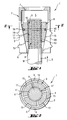
- the expansion dowel 1 comprises a sleeve 2, which is provided with axial slots 4 Has spreading area 3.
- the sleeve 2 has an axial bore 5, which is in the expansion area 3 has a tapered section. According to the illustrated Embodiment extends the spreading area 3, based on that by the Arrow S indicated setting direction, essentially over the rear half of the Sleeve 2 and the axial bore 5 tapers to the rear end 6 of the sleeve 2.
- Am an annular stop 7 is arranged opposite the front end of the sleeve 2, which protrudes into the axial bore 5 of the sleeve 2 and narrows it.
- the sleeve 2 are preferably provided with ring-shaped projections 19 protrude from the outer surface 20 of the sleeve 2.
- an expansion body 8 is arranged axially displaceable.
- the Spreading body 8 has a conical part of its longitudinal extent Outer contour on.
- the conical outer contour is preferably at the taper of the tapered section of the axial bore 5 of the sleeve 2 approximated.
- the expansion body 8 is provided with a cylindrical through hole 9, the Inner diameter determines the nominal connection diameter of the expansion anchor 1.
- the expansion body 8 consists of four Clamping segments 11-14, which are held together by an O-ring 10, which in a groove 16 is arranged in the outer surfaces 15 of the clamping segments 11-14.
- the O-ring can be expanded elastically.
- the clamping segments 11-14 are Pushing in an anchor rod A is radially movable.
- the largest outside diameter of the Spreading body 8 in the cylindrical section is larger than that by the annular Stop 7 at the front end of the sleeve 2 narrowed inner diameter of the axial bore 5.
- the inner sides 17 of the clamping segments 11-14 are provided with profiles 18 which are preferably thread-like.
- profiles 18 which are preferably thread-like.
- the profiles 18 can also be designed like a blade, in order to load the anchor rod A into the to emboss a corresponding profile P on the softer lateral surface M.
- the inner sides 17 of the clamping segments 11-14 can also be a Have coating that is softer than the material of the anchor rod A.
- the spike dowel 1 To create a fastening with the spike dowel 1 according to the invention, it is used inserted into a borehole.
- the ring-shaped projections 19 on the Outer surface 20 of the sleeve 2 ensure a certain pre-fixation of the expansion anchor 1, so that this does not come out of the borehole, for example, when installed overhead falls out.
- the expansion anchor 1 is anchored at the same time as the connection of the Anchor rod A by inserting it into the through hole 9 of the expansion body 8 is inserted.
- the expansion body 8 against the annular Stop 7 pushed. As soon as the expansion body 8 abuts the stop 7, the penetrates Anchor rod A during further advancement into the through hole 9 of the Spreading body 8 a.
- the design of the expansion anchor according to the invention offers a number of advantages.
- the expansion body made of radially resiliently expandable clamping segments for the Anchor rod is a quick connection system. After inserting the expansion anchor in the drill hole and the subsequent quick connection of the anchor rod can immediately the load is initiated. The expansion area of the sleeve of the expansion anchor expanded radially and the expansion anchor is anchored in the borehole.
- the invention Expansion dowel offers great flexibility with regard to the usable Anchor rods. These can be profiled in the manner of a lateral surface have metric thread or a Whitworth thread. Reinforcing bars too with radial or helical profiles of their lateral surface be used. In the case of threaded anchor rods there is also one Height adjustment of the connection components. The one from individual segments Existing expansion bodies even allow anchor rods to be inserted, the Outside diameter exceeds the nominal connection diameter of the expansion anchor.
Landscapes
- Engineering & Computer Science (AREA)
- General Engineering & Computer Science (AREA)
- Mechanical Engineering (AREA)
- Dowels (AREA)
- Joining Of Building Structures In Genera (AREA)
- Mutual Connection Of Rods And Tubes (AREA)
Applications Claiming Priority (2)
| Application Number | Priority Date | Filing Date | Title |
|---|---|---|---|
| DE19740823A DE19740823A1 (de) | 1997-09-17 | 1997-09-17 | Spreizdübel |
| DE19740823 | 1997-09-17 |
Publications (3)
| Publication Number | Publication Date |
|---|---|
| EP0905385A2 true EP0905385A2 (fr) | 1999-03-31 |
| EP0905385A3 EP0905385A3 (fr) | 2000-04-05 |
| EP0905385B1 EP0905385B1 (fr) | 2004-11-24 |
Family
ID=7842596
Family Applications (1)
| Application Number | Title | Priority Date | Filing Date |
|---|---|---|---|
| EP98810872A Expired - Lifetime EP0905385B1 (fr) | 1997-09-17 | 1998-09-02 | Cheville d'expansion |
Country Status (6)
| Country | Link |
|---|---|
| US (1) | US6062784A (fr) |
| EP (1) | EP0905385B1 (fr) |
| JP (1) | JP4237303B2 (fr) |
| KR (1) | KR19990029800A (fr) |
| CN (1) | CN1211689A (fr) |
| DE (2) | DE19740823A1 (fr) |
Families Citing this family (37)
| Publication number | Priority date | Publication date | Assignee | Title |
|---|---|---|---|---|
| DE10023675C2 (de) * | 2000-05-16 | 2003-04-17 | Arno Giehl | Mutter |
| DE10052445A1 (de) * | 2000-10-23 | 2002-05-02 | Hilti Ag | Schnellmontagemutter |
| DE10118374A1 (de) * | 2001-04-12 | 2002-10-17 | Fischer Artur Werke Gmbh | Verfahren zur Herstellung eines Spreizankers |
| US7011281B2 (en) * | 2002-02-28 | 2006-03-14 | Karl Guthrie | Expansion bolt |
| FR2841612B1 (fr) | 2002-06-28 | 2008-07-04 | Renault Sa | Dispositif de fixation expansible pour l'ancrage d'un equipement a support |
| DE10256862A1 (de) * | 2002-12-05 | 2004-06-24 | Hilti Ag | Schnellmontagemutter |
| AT7093U1 (de) * | 2003-12-15 | 2004-10-25 | Komperdell Sportartikel Gmbh | Klemmvorrichtung für teleskopartig ineinander geschobene rohre |
| US7357363B2 (en) * | 2003-12-30 | 2008-04-15 | Karl Guthrie | Expansion bolt |
| US7416375B2 (en) * | 2005-07-26 | 2008-08-26 | Perigee Design Incorporated | Threaded coupling mechanism having quick engaging and disengaging feature |
| ITMI20051441A1 (it) * | 2005-07-26 | 2007-01-27 | Pronzati Giuseppe Gipron Spa | Sistema di bloccaggio per tubi |
| DE102005046362A1 (de) * | 2005-09-28 | 2007-04-05 | Airbus Deutschland Gmbh | Klemmstück und Haltevorrichtung mit einem derartigen Klemmstück |
| US7744320B2 (en) * | 2006-06-05 | 2010-06-29 | Illinois Tool Works Inc. | Anchor bolt and annularly grooved expansion sleeve assembly exhibiting high pull-out resistance, particularly under cracked concrete test conditions |
| US7811037B2 (en) * | 2006-06-05 | 2010-10-12 | Illinois Tool Works Inc. | Anchor bolt and annularly grooved expansion sleeve assembly exhibiting high pull-out resistance, particularly under cracked concrete test conditions |
| US8540471B2 (en) * | 2006-07-05 | 2013-09-24 | Visenut Llc | Quick attaching and detaching nut |
| US20080008556A1 (en) * | 2006-07-05 | 2008-01-10 | Steven Dvorak | Quick Attaching and Detaching Nut |
| US20080038079A1 (en) * | 2006-08-14 | 2008-02-14 | Bobon James L | Adjustable concrete drop-in anchor |
| US20090056267A1 (en) * | 2007-07-12 | 2009-03-05 | Reeves Eric William | Expansible hole anchor |
| US7984932B2 (en) | 2007-12-19 | 2011-07-26 | Stinger Wellhead Protection, Inc. | Threaded union for tubulars used in high-pressure fluid applications |
| US20110182697A1 (en) * | 2010-01-25 | 2011-07-28 | Smith Ronald A | Multi-rod thread clamping device |
| EP2395247A1 (fr) * | 2010-06-10 | 2011-12-14 | Powers Products III, LLC | Ancrage réduit et systèmes d'ancrage réduit |
| JP5848632B2 (ja) * | 2012-02-27 | 2016-01-27 | 特許機器株式会社 | 吊りボルト取付具 |
| DE102012203865A1 (de) * | 2012-03-13 | 2013-09-19 | Hilti Aktiengesellschaft | Spreizanker |
| US8881478B2 (en) | 2012-06-22 | 2014-11-11 | Simpson Strong-Tie Company, Inc. | Ratcheting take-up device |
| JP2014152905A (ja) * | 2013-02-13 | 2014-08-25 | Howa Corp | アンカーボルト |
| JP6224715B2 (ja) * | 2013-08-08 | 2017-11-01 | 株式会社豊和 | アンカーボルト |
| US9394706B2 (en) | 2013-10-08 | 2016-07-19 | Simpson Strong-Tie Company, Inc. | Concrete anchor |
| KR101497462B1 (ko) * | 2014-01-10 | 2015-03-02 | 삼성중공업 주식회사 | 배관의 플랜지용 가스켓 장착 지그 |
| US9163655B2 (en) | 2014-01-14 | 2015-10-20 | Kaoru Taneichi | Thrust nut |
| JP6374235B2 (ja) * | 2014-06-27 | 2018-08-15 | 株式会社豊和 | アンカーボルト |
| US10590981B2 (en) | 2015-03-19 | 2020-03-17 | 2738297 Ontario Inc. | Fastener assembly |
| JP6618814B2 (ja) * | 2016-01-22 | 2019-12-11 | 未来工業株式会社 | ボルト体取着具 |
| CN105742831A (zh) * | 2016-03-28 | 2016-07-06 | 国家电网公司 | 一种穿刺线夹安装座 |
| JP7018641B2 (ja) * | 2017-04-27 | 2022-02-14 | 株式会社ロイヤル | 棚板固定装置 |
| NO344799B1 (no) * | 2017-11-01 | 2020-05-04 | Bondura Tech As | Boltsammenstilling for aksial og radial oppspenning av elementer sammenføyd ved hjelp av skruer |
| JP7325080B2 (ja) * | 2019-02-18 | 2023-08-14 | Next Innovation合同会社 | 接合手段及び部材の接合方法 |
| CN109989975B (zh) * | 2019-03-28 | 2020-07-07 | 广东珠江工程总承包有限公司 | 一种用于安装在建筑墙体的膨胀螺套 |
| KR102325683B1 (ko) * | 2020-02-18 | 2021-11-17 | (주)케이모듈 | 구조재 정착용 커플러를 이용한 신규구조물의 정착 시공방법 |
Family Cites Families (12)
| Publication number | Priority date | Publication date | Assignee | Title |
|---|---|---|---|---|
| DE2221267C3 (de) * | 1971-04-30 | 1978-10-05 | Giorgio Mailand Feige (Italien) | Spreizdübel |
| FR2191640A5 (fr) * | 1972-07-06 | 1974-02-01 | Rapid Sa | |
| DE3124823A1 (de) * | 1981-06-24 | 1983-01-13 | Hilti AG, 9494 Schaan | Spreizduebel |
| JPS61150517U (fr) * | 1985-03-08 | 1986-09-17 | ||
| JPH0786365B2 (ja) * | 1987-12-18 | 1995-09-20 | 株式会社ミヤナガ | スリ−ブの製造方法 |
| US5154558A (en) * | 1990-09-04 | 1992-10-13 | Mccallion James P | Blind anchor for use with unthreaded rod |
| JPH0756286B2 (ja) * | 1990-10-23 | 1995-06-14 | スガツネ工業株式会社 | 連結装置 |
| US5324150A (en) * | 1991-11-06 | 1994-06-28 | Fullerton Robert L | Quick acting nut or coupling assembly |
| US5340252A (en) * | 1993-06-01 | 1994-08-23 | The United States Of America As Represented By The United States National Aeronautics And Space Administration | Quick connect fastener |
| JPH07139534A (ja) * | 1993-11-15 | 1995-05-30 | Matsushita Electric Works Ltd | ボルト・ナット固定装置 |
| JPH08320009A (ja) * | 1995-05-24 | 1996-12-03 | Ishikawajima Kenzai Shoji Kk | 接合構造 |
| US5846041A (en) * | 1997-07-10 | 1998-12-08 | The United States Of America As Represented By The United States Department Of Energy | Nonrotating, self-centering anchor assembly for anchoring a bolt in a borehole |
-
1997
- 1997-09-17 DE DE19740823A patent/DE19740823A1/de not_active Withdrawn
-
1998
- 1998-09-02 EP EP98810872A patent/EP0905385B1/fr not_active Expired - Lifetime
- 1998-09-02 DE DE59812299T patent/DE59812299D1/de not_active Expired - Lifetime
- 1998-09-15 CN CN98119191A patent/CN1211689A/zh active Pending
- 1998-09-15 KR KR1019980037956A patent/KR19990029800A/ko not_active Application Discontinuation
- 1998-09-16 US US09/153,915 patent/US6062784A/en not_active Expired - Lifetime
- 1998-09-17 JP JP26325098A patent/JP4237303B2/ja not_active Expired - Fee Related
Non-Patent Citations (1)
| Title |
|---|
| None |
Also Published As
| Publication number | Publication date |
|---|---|
| EP0905385B1 (fr) | 2004-11-24 |
| KR19990029800A (ko) | 1999-04-26 |
| DE19740823A1 (de) | 1999-03-18 |
| DE59812299D1 (de) | 2004-12-30 |
| JP4237303B2 (ja) | 2009-03-11 |
| CN1211689A (zh) | 1999-03-24 |
| US6062784A (en) | 2000-05-16 |
| EP0905385A3 (fr) | 2000-04-05 |
| JPH11148505A (ja) | 1999-06-02 |
Similar Documents
| Publication | Publication Date | Title |
|---|---|---|
| EP0905385B1 (fr) | Cheville d'expansion | |
| EP0068227B1 (fr) | Boulon d'ancrage | |
| EP0067941B1 (fr) | Cheville expansible pour l'ancrage dans des trous de forage réalisés avec un élargissement intérieur conique | |
| DE2617191C2 (de) | Spreizdübel | |
| DE3329732A1 (de) | Spreizanker | |
| DE1750663B2 (de) | Ankerschraube | |
| DE3110485A1 (de) | Spreizanker | |
| DE3737549A1 (de) | Spreizduebel fuer die verankerung in hinterschnittenen bohrloechern | |
| DD299202A5 (de) | Vorrichtung zur befestigung eines insbesondere rohrfoermigen bauteils an einer wand oder dgl. | |
| DE2754910A1 (de) | Befestigungsvorrichtung zum einsetzen in eine aufnahme in einer wandung oder zum verbinden von aufnahmen aufweisenden elementen | |
| DE3139174C2 (de) | Ankerbolzen | |
| DE2632487A1 (de) | Spreizduebel | |
| DE2435152A1 (de) | Spreizduebel | |
| DE3840914A1 (de) | Befestigungssystem | |
| DE7323455U (de) | Befestigungselement zur Verankerung in Bauwerksteilen | |
| EP0108334A1 (fr) | Vis pour cheville en matière plastique | |
| DE3404306A1 (de) | Spreiznagel | |
| DE3145319C2 (fr) | ||
| DE3425237A1 (de) | Spreizduebel | |
| DE3237059A1 (de) | Spreizduebel mit gewindebolzen und spreizhuelse | |
| DE1810295A1 (de) | Spreizduebel | |
| EP0760429B1 (fr) | Cheville d'expansion en matière plastique | |
| DE2914074A1 (de) | Bauwerksanker fuer eine verankerung in einer bohrung | |
| DE7138416U (de) | Spreizdübel | |
| DE3336809C2 (de) | Kunststoffdübel für Leichtbetone, insbesondere Gas- oder Schaumbetone |
Legal Events
| Date | Code | Title | Description |
|---|---|---|---|
| PUAI | Public reference made under article 153(3) epc to a published international application that has entered the european phase |
Free format text: ORIGINAL CODE: 0009012 |
|
| AK | Designated contracting states |
Kind code of ref document: A2 Designated state(s): CH DE FR GB LI |
|
| AX | Request for extension of the european patent |
Free format text: AL;LT;LV;MK;RO;SI |
|
| PUAL | Search report despatched |
Free format text: ORIGINAL CODE: 0009013 |
|
| AK | Designated contracting states |
Kind code of ref document: A3 Designated state(s): AT BE CH CY DE DK ES FI FR GB GR IE IT LI LU MC NL PT SE |
|
| AX | Request for extension of the european patent |
Free format text: AL;LT;LV;MK;RO;SI |
|
| 17P | Request for examination filed |
Effective date: 20001005 |
|
| AKX | Designation fees paid |
Free format text: CH DE FR GB LI |
|
| 17Q | First examination report despatched |
Effective date: 20030707 |
|
| GRAP | Despatch of communication of intention to grant a patent |
Free format text: ORIGINAL CODE: EPIDOSNIGR1 |
|
| GRAS | Grant fee paid |
Free format text: ORIGINAL CODE: EPIDOSNIGR3 |
|
| GRAA | (expected) grant |
Free format text: ORIGINAL CODE: 0009210 |
|
| AK | Designated contracting states |
Kind code of ref document: B1 Designated state(s): CH DE FR GB LI |
|
| REG | Reference to a national code |
Ref country code: GB Ref legal event code: FG4D Free format text: NOT ENGLISH |
|
| REG | Reference to a national code |
Ref country code: CH Ref legal event code: EP |
|
| REF | Corresponds to: |
Ref document number: 59812299 Country of ref document: DE Date of ref document: 20041230 Kind code of ref document: P |
|
| GBT | Gb: translation of ep patent filed (gb section 77(6)(a)/1977) |
Effective date: 20050115 |
|
| PLBE | No opposition filed within time limit |
Free format text: ORIGINAL CODE: 0009261 |
|
| STAA | Information on the status of an ep patent application or granted ep patent |
Free format text: STATUS: NO OPPOSITION FILED WITHIN TIME LIMIT |
|
| ET | Fr: translation filed | ||
| 26N | No opposition filed |
Effective date: 20050825 |
|
| PGFP | Annual fee paid to national office [announced via postgrant information from national office to epo] |
Ref country code: GB Payment date: 20060830 Year of fee payment: 9 Ref country code: CH Payment date: 20060830 Year of fee payment: 9 |
|
| REG | Reference to a national code |
Ref country code: CH Ref legal event code: PL |
|
| GBPC | Gb: european patent ceased through non-payment of renewal fee |
Effective date: 20070902 |
|
| PG25 | Lapsed in a contracting state [announced via postgrant information from national office to epo] |
Ref country code: LI Free format text: LAPSE BECAUSE OF NON-PAYMENT OF DUE FEES Effective date: 20070930 Ref country code: CH Free format text: LAPSE BECAUSE OF NON-PAYMENT OF DUE FEES Effective date: 20070930 |
|
| PG25 | Lapsed in a contracting state [announced via postgrant information from national office to epo] |
Ref country code: GB Free format text: LAPSE BECAUSE OF NON-PAYMENT OF DUE FEES Effective date: 20070902 |
|
| PGFP | Annual fee paid to national office [announced via postgrant information from national office to epo] |
Ref country code: DE Payment date: 20120808 Year of fee payment: 15 Ref country code: FR Payment date: 20120926 Year of fee payment: 15 |
|
| REG | Reference to a national code |
Ref country code: FR Ref legal event code: ST Effective date: 20140530 |
|
| REG | Reference to a national code |
Ref country code: DE Ref legal event code: R119 Ref document number: 59812299 Country of ref document: DE Effective date: 20140401 |
|
| PG25 | Lapsed in a contracting state [announced via postgrant information from national office to epo] |
Ref country code: DE Free format text: LAPSE BECAUSE OF NON-PAYMENT OF DUE FEES Effective date: 20140401 Ref country code: FR Free format text: LAPSE BECAUSE OF NON-PAYMENT OF DUE FEES Effective date: 20130930 |