EP0904960B1 - Bandage pneumatique sans crampons - Google Patents
Bandage pneumatique sans crampons Download PDFInfo
- Publication number
- EP0904960B1 EP0904960B1 EP98307914A EP98307914A EP0904960B1 EP 0904960 B1 EP0904960 B1 EP 0904960B1 EP 98307914 A EP98307914 A EP 98307914A EP 98307914 A EP98307914 A EP 98307914A EP 0904960 B1 EP0904960 B1 EP 0904960B1
- Authority
- EP
- European Patent Office
- Prior art keywords
- depth
- angle
- tyre
- lateral
- circumferential
- Prior art date
- Legal status (The legal status is an assumption and is not a legal conclusion. Google has not performed a legal analysis and makes no representation as to the accuracy of the status listed.)
- Expired - Lifetime
Links
Images

Classifications
-
- B—PERFORMING OPERATIONS; TRANSPORTING
- B60—VEHICLES IN GENERAL
- B60C—VEHICLE TYRES; TYRE INFLATION; TYRE CHANGING; CONNECTING VALVES TO INFLATABLE ELASTIC BODIES IN GENERAL; DEVICES OR ARRANGEMENTS RELATED TO TYRES
- B60C11/00—Tyre tread bands; Tread patterns; Anti-skid inserts
- B60C11/03—Tread patterns
- B60C11/13—Tread patterns characterised by the groove cross-section, e.g. for buttressing or preventing stone-trapping
-
- B—PERFORMING OPERATIONS; TRANSPORTING
- B60—VEHICLES IN GENERAL
- B60C—VEHICLE TYRES; TYRE INFLATION; TYRE CHANGING; CONNECTING VALVES TO INFLATABLE ELASTIC BODIES IN GENERAL; DEVICES OR ARRANGEMENTS RELATED TO TYRES
- B60C11/00—Tyre tread bands; Tread patterns; Anti-skid inserts
-
- B—PERFORMING OPERATIONS; TRANSPORTING
- B60—VEHICLES IN GENERAL
- B60C—VEHICLE TYRES; TYRE INFLATION; TYRE CHANGING; CONNECTING VALVES TO INFLATABLE ELASTIC BODIES IN GENERAL; DEVICES OR ARRANGEMENTS RELATED TO TYRES
- B60C11/00—Tyre tread bands; Tread patterns; Anti-skid inserts
- B60C11/03—Tread patterns
- B60C11/11—Tread patterns in which the raised area of the pattern consists only of isolated elements, e.g. blocks
-
- B—PERFORMING OPERATIONS; TRANSPORTING
- B60—VEHICLES IN GENERAL
- B60C—VEHICLE TYRES; TYRE INFLATION; TYRE CHANGING; CONNECTING VALVES TO INFLATABLE ELASTIC BODIES IN GENERAL; DEVICES OR ARRANGEMENTS RELATED TO TYRES
- B60C11/00—Tyre tread bands; Tread patterns; Anti-skid inserts
- B60C11/03—Tread patterns
- B60C11/13—Tread patterns characterised by the groove cross-section, e.g. for buttressing or preventing stone-trapping
- B60C11/1307—Tread patterns characterised by the groove cross-section, e.g. for buttressing or preventing stone-trapping with special features of the groove walls
- B60C11/1323—Tread patterns characterised by the groove cross-section, e.g. for buttressing or preventing stone-trapping with special features of the groove walls asymmetric
-
- B—PERFORMING OPERATIONS; TRANSPORTING
- B60—VEHICLES IN GENERAL
- B60C—VEHICLE TYRES; TYRE INFLATION; TYRE CHANGING; CONNECTING VALVES TO INFLATABLE ELASTIC BODIES IN GENERAL; DEVICES OR ARRANGEMENTS RELATED TO TYRES
- B60C11/00—Tyre tread bands; Tread patterns; Anti-skid inserts
- B60C11/03—Tread patterns
- B60C11/12—Tread patterns characterised by the use of narrow slits or incisions, e.g. sipes
- B60C11/1204—Tread patterns characterised by the use of narrow slits or incisions, e.g. sipes with special shape of the sipe
- B60C2011/1213—Tread patterns characterised by the use of narrow slits or incisions, e.g. sipes with special shape of the sipe sinusoidal or zigzag at the tread surface
-
- Y—GENERAL TAGGING OF NEW TECHNOLOGICAL DEVELOPMENTS; GENERAL TAGGING OF CROSS-SECTIONAL TECHNOLOGIES SPANNING OVER SEVERAL SECTIONS OF THE IPC; TECHNICAL SUBJECTS COVERED BY FORMER USPC CROSS-REFERENCE ART COLLECTIONS [XRACs] AND DIGESTS
- Y10—TECHNICAL SUBJECTS COVERED BY FORMER USPC
- Y10S—TECHNICAL SUBJECTS COVERED BY FORMER USPC CROSS-REFERENCE ART COLLECTIONS [XRACs] AND DIGESTS
- Y10S152/00—Resilient tires and wheels
- Y10S152/902—Non-directional tread pattern having no circumferential rib and having blocks defined by circumferential grooves and transverse grooves
Definitions
- the present invention relates to a pneumatic tyre, more particularly to an improved tread structure for studless tyres capable of improving uneven wear resistance without deteriorating snow performances.
- studless tyres used in wet and dry conditions are provided with block type tread patterns to obtain massive grip on snowy roads. Further, in the tread portion relatively soft rubber compounds are used to improve friction and adhesion to icy road surfaces, so that good snow performances or running performances on snowy and icy roads are provided.
- an object of the present invention to provide a tyre in which the uneven wear resistance is improved without sacrificing wet performance.
- a pneumatic tyre comprises a tread portion defined by a tread rubber having a Shore A hardness of not more than 65 degrees at 20 degrees C, provided with at least one circumferential row of blocks, separated circumferentially of the tyre by lateral grooves and having circumferential edges adjacent to the lateral grooves, each of the circumferential edges having a mean inclination angle of 0 to 60 degrees with respect to the tyre axial direction, where the mean inclination angle is defined as that of a straight line drawn between the axial ends of the circumferential edge, wherein the sidewalls of the lateral grooves on one side in the tyre circumferential direction each comprise a first upper slope and a first lower slope, the first upper slope extending from the top of the adjacent block to a first point at a depth h1, while inclining at an angle ⁇ 1, the first lower slope extending from said first point towards the groove bottom, while inclining at an angle ⁇ 2 smaller than angle ⁇ 1, the remaining side
- the above-mentioned portion (A) corresponds to one of the axial end parts of the lateral groove and the portion (B) corresponds to the other axial end part.
- the axial positions of the portion (A) and portion (B) are reversed between the axially adjacent rows.
- a studless tyre is a belted radial ply tyre, which comprises a tread portion, a pair of axially spaced bead portions, a pair of sidewalls extending therebetween, a carcass extending between the bead portions and a belt disposed radially outside the carcass and inside a tread rubber.
- the tread rubber has a Shore A hardness of not more than 65 degrees but preferably not less than 45 degrees at a temperature of 20 degrees C, and the radially outer surface thereof defines the tread. If the hardness is more than 65 degrees, required adhesiveness and friction on icy roads can not be obtained and thus, ice grip is liable to decrease. If the hardness is excessively low, for example less than 45 degrees, the wear resistance and snow grip greatly decrease.
- the tread portion is provided with main grooves 2 extending continuously in the tyre circumferential direction and lateral grooves 3 extending crosswise to the main grooves 2 to form rows of blocks 5.
- the main grooves 2 comprise three straight grooves; a central groove on the tyre equator C and a side groove on each side thereof.
- the lateral grooves 3 comprise axially inner grooves each extending from the central groove to one of the side grooves, and axially outer grooves each extending from one of the side grooves to the adjacent tread edge.
- Each of the lateral grooves 3 has a crank-shaped configuration.
- the tread portion is divided into four rows R of circumferentially spaced blocks 5.
- the main grooves 2 and lateral grooves 3 have a groove top width of 6 to 20 mm and a maximum groove depth H of 8 to 13 mm in the normally inflated state.
- main grooves 2 apart from a straight configuration, various zigzag or wavy configurations may be used. However, a gentle wave or zigzag is preferable.
- lateral grooves 3 apart from a crank shape or zigzag shape, various shapes, e.g. straight, wavy or curved configurations may be used.
- Each of the blocks 5 has a pair of circumferential edges 10 and a pair of axial edges.
- a circumferential edge 10 is the edge formed between the top face of the block and a side face thereof facing one of the lateral grooves, namely a sidewall of the lateral groove.
- the circumferential edge 10 is the upper edge of the sidewall of the lateral groove as seen in Fig. 1.
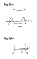
- the blocks 5 are each provided with at least one sipe extending from one of the axial edges to the other.
- a plurality of parallel zigzag sipes 6 are formed, which extend generally parallel to the axial direction of the tyre.
- each circumferential edge 10 comprises side parts 17A and 17B extending substantially parallel to the tyre axial direction and an inclined middle part 19 extending therebetween.
- the mean inclination angle ⁇ of each circumferential edge 10 is set in the range of from 0 to 60 degrees with respect to the tyre axial direction.
- the mean inclination angle ⁇ is defined as the angle of a straight line J drawn between the axial ends P of the edge 10. If the angle ⁇ is more than 60 degrees, road grip is liable to become insufficient, and further acute angle corners are formed on the blocks 5 which are liable to be torn off in service.
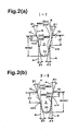
- Each of the lateral grooves 3 has at least two different sectional shapes related to the block arrangement.
- sidewall 9A the sidewalls of the lateral grooves 3 on one side in the tyre circumferential direction
- sidewall 9B the remaining sidewalls on the other side
- the sidewall 9A comprises a first upper slope S1U and a first lower slope S1D.
- Sidewall 9B comprises a second upper slope S2U and a second lower slope S2D.
- the first upper slope S1U extends straight from the block top to a first point h1X at a depth h1, while inclining at an angle ⁇ 1.
- the first lower slope S1D extends from the first point h1X towards the groove bottom, while inclining at an angle ⁇ 2 smaller than the angle ⁇ 1.
- the second upper slope S2U extends straight from the block top to a second point h2X at a different depth h2 than the depth h1, while inclining at an angle ⁇ 1.
- the second lower slope S2D extends straight from the second point h2X towards the groove bottom, while inclining at an angle ⁇ 2 smaller than the angle ⁇ 1.
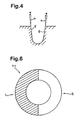
- the inclining directions of all the slopes are such that the lateral groove width decreases radially inwards, and all the angles are measured with respect to a normal direction N to the block top in a cross section at a right angle to the lateral groove 3.
- the groove bottom 20 extending between the two sidewalls 9A and 9B is defined by an arc. This arc is connected to each straight line of the sidewalls without forming an inflection point.
- the depth h1 of the first point h1X is more than the depth h2 of the second point h2X
- the ratio h1/Ha of the depth h1 to the groove depth Ha(H) is not more than 0.8 and more preferably not more than 0.6, but not less than 0.3 and more preferably not less than 0.4.
- the depth h2 of the second point h2X is more than the depth h1 of the first point h1X
- the ratio h2/Hb of the depth h2 to the groove depth Hb(H) is not more than 0.8 and more preferably not more than 0.6, but not less than 0.3 and more preferably not less than 0.4.
- the axial positions (A) and (B) correspond to the axially outer end parts of the lateral grooves, that is, the above-mentioned axial parts 17A and 17B.
- sectional shapes are combined with axial positions rather than the lateral groove shape.
- the depth h1 of the first point h1X is larger in the position (A) than the position B, and the angle ⁇ 1 is 8 to 20 degrees in the position (A) and 8 to 15 degrees in the position (B), and the angle ⁇ 2 is 3 to 10 degrees in the position (A) and position (B).
- the depth h2 of the second point h2X is smaller in the position (A) than the position (B), and the angle ⁇ 1 is 8 to 15 degrees in the position (A) and 8 to 20 degrees in the position (B), and the angle ⁇ 2 is 3 to 10 degrees in the position (A) and position (B).
- the edge effect from the circumferential edges 10 on icy roads decreases, and the lateral groove volume decreases to deteriorate drainage performance and snow performance. If the angles are under the above-mentioned ranges, it becomes difficult to improve the uneven wear resistance.
- the blocks 5 are increased in circumferential rigidity. Further, as the lateral groove 3 has at least two different sectional shapes, deformations of the blocks 5 during braking and acceleration can be effectively controlled, and the uneven wear resistance can be improved.
- the ratio h1/Ha, h2/Hb is more than 0.8 or less than 0.3, the above-mentioned effect on improving the block rigidity decreases and the uneven wear resistance is not improved sufficiently.
- the lateral grooves in each of the block rows R are arranged in the same way, and in this example, the lateral grooves are generally inclined to the same direction due to the crank shape.
- the inclinations are, from the left row to the right row, left-side upward, right-side upward, right-side upward and left-side upward.
- the circumferential pitches of the lateral grooves are shifted by about one half pitch. Therefore, the tread pattern is a bi-directional tread pattern independently of the above-mentioned arrangement of the two different sectional shapes.
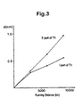
- Test tyres T1 having the block pattern shown in Fig.1 were made and tested for uneven wear (step wear) resistance.
- a 2000cc FF passenger car provided on the front axle with the test tyres T1 was run on a dry test course at a speed of 80 km/h, and the average of uneven wear d (Fig.5(b)) was measured at running distances of 3000 km, 6000 km and 9000 km.
- test tyres of size 175/80R14 having the same internal construction and the same block pattern shown in Fig.1 except for the lateral groove sidewall construction were made and tested for snow performances.
- the specifications are shown in Table 2.
- test tyres were mounted on the front axle of a 2000cc FF passenger car.
- the tyres according to the present invention can be improved in the uneven wear resistance, while maintaining the snow performances the same level as a conventional tyre.
Landscapes
- Engineering & Computer Science (AREA)
- Mechanical Engineering (AREA)
- Tires In General (AREA)
Claims (3)
- Pneumatique comprenant une partie de bande de roulement délimitée par un caoutchouc de bande de roulement ayant une dureté Shore A qui ne dépasse pas 65° à 20 °C, ayant au moins une rangée circonférentielle de blocs (5) séparés circonférentiellement par rapport au pneumatique par des gorges latérales (3) et ayant des bords circonférentiels (10) adjacents aux gorges latérales (3), chacun des bords circonférentiels (10) ayant un angle moyen d'inclinaison γ compris entre 0 et 60° par rapport à la direction axiale du pneumatique, l'angle moyen d'inclinaison γ étant défini comme celui d'une droite (J) tracée entre les extrémités axiales (P) du bord circonférentiel (10), caractérisé en ce que les flancs (9A) des gorges latérales d'un premier côté dans la direction circonférentielle du pneumatique comportent chacun une première pente supérieure (S1U) et une première pente inférieure (S1D), la première pente supérieure (S1U) s'étendant depuis la partie supérieure du bloc adjacent vers un premier point à une profondeur h1, avec inclinaison suivant un angle α1, la première pente inférieure (S1D) s'étendant depuis le premier point vers le fond de la gorge, avec inclinaison suivant un angle α2 inférieur à l'angle α1, les flancs restants (9B) des gorges latérales de l'autre côté comprenant chacun une seconde pente supérieure (S2U) et une seconde pente inférieure (S2D), la seconde pente supérieure (S2U) s'étendant depuis la partie supérieure du bloc adjacent vers un second point qui est à une profondeur h2 différente de la profondeur h1, en s'inclinant d'un angle β1, la seconde pente inférieure (S2D) s'étendant directement du second point vers le fond de la gorge, en s'inclinant d'un angle β2 inférieur à l'angle β1, les directions d'inclinaison de toutes les pentes (S1U, S1D, S2U et S2D) étant telles que les largeurs des gorges latérales diminuent radialement vers l'intérieur, et tous les angles sont mesurés par rapport à une direction normale à la partie supérieure du bloc en coupe perpendiculaire à la gorge latérale, et, pour chacune des gorges latérales (3), dans une partie (A), la profondeur h1 est supérieure à la profondeur h2 mais ne dépasse pas 0,8 fois la profondeur de la gorge latérale et, dans une autre partie (B), la profondeur h2 est supérieure à la profondeur h1 mais ne dépasse pas 0,8 fois la profondeur de la gorge latérale.
- Pneumatique selon la revendication 1, caractérisé en ce que ladite partie (A) correspond à l'une des extrémités axiales de la gorge latérale et ladite partie (B) correspond à l'autre extrémité axiale.
- Pneumatique selon la revendication 1 ou 2, caractérisé en ce que la rangée circonférentielle au moins de blocs est formée de plusieurs rangées circonférentielles de blocs, et les positions axiales de la partie (A) et de la partie (B) sont inversées entre les rangées axialement adjacentes.
Applications Claiming Priority (3)
| Application Number | Priority Date | Filing Date | Title |
|---|---|---|---|
| JP266279/97 | 1997-09-30 | ||
| JP26627997 | 1997-09-30 | ||
| JP26627997A JP3361256B2 (ja) | 1997-09-30 | 1997-09-30 | 雪路用空気入りタイヤ |
Publications (3)
| Publication Number | Publication Date |
|---|---|
| EP0904960A2 EP0904960A2 (fr) | 1999-03-31 |
| EP0904960A3 EP0904960A3 (fr) | 2000-11-02 |
| EP0904960B1 true EP0904960B1 (fr) | 2003-12-17 |
Family
ID=17428757
Family Applications (1)
| Application Number | Title | Priority Date | Filing Date |
|---|---|---|---|
| EP98307914A Expired - Lifetime EP0904960B1 (fr) | 1997-09-30 | 1998-09-29 | Bandage pneumatique sans crampons |
Country Status (4)
| Country | Link |
|---|---|
| US (1) | US6079464A (fr) |
| EP (1) | EP0904960B1 (fr) |
| JP (1) | JP3361256B2 (fr) |
| DE (1) | DE69820559T2 (fr) |
Cited By (1)
| Publication number | Priority date | Publication date | Assignee | Title |
|---|---|---|---|---|
| CN1647956B (zh) * | 2004-01-27 | 2010-07-21 | 住友橡胶工业株式会社 | 轮胎噪音降低系统及充气轮胎 |
Families Citing this family (28)
| Publication number | Priority date | Publication date | Assignee | Title |
|---|---|---|---|---|
| US8277922B2 (en) * | 1998-10-05 | 2012-10-02 | 3M Innovative Properties Company | Stem web |
| US20120027990A1 (en) * | 1998-10-05 | 2012-02-02 | 3M Innovative Properties Company | Article for wet applications |
| KR100839139B1 (ko) * | 1998-10-30 | 2008-06-19 | 피렐리 타이어 소시에떼 퍼 아찌오니 | 특히 화물차 및 화물차와 유사한 차량용 원동 차량 타이어 |
| JP3332357B2 (ja) * | 1999-07-26 | 2002-10-07 | 住友ゴム工業株式会社 | 空気入りタイヤ |
| US6640858B2 (en) * | 1999-12-07 | 2003-11-04 | Sumitomo Rubber Industries, Ltd. | Tire having tread grooves having right-hand groove wall and left-hand groove wall |
| JP3363419B2 (ja) * | 1999-12-24 | 2003-01-08 | 住友ゴム工業株式会社 | 重荷重用ラジアルタイヤ |
| EP1345784B1 (fr) * | 2000-11-28 | 2012-07-04 | Cooper Tire & Rubber Company | Pneu comportant des rainures a cotes denteles |
| USD451452S1 (en) | 2001-02-19 | 2001-12-04 | The Goodyear Tire & Rubber Company | Tire tread |
| USD457126S1 (en) | 2001-05-18 | 2002-05-14 | The Goodyear Tire & Rubber Company | Tire tread |
| JP4634644B2 (ja) * | 2001-05-22 | 2011-02-16 | 住友ゴム工業株式会社 | 空気入りタイヤ |
| CN100467289C (zh) * | 2001-09-17 | 2009-03-11 | 普利司通株式会社 | 充气轮胎 |
| JP4295728B2 (ja) * | 2002-11-06 | 2009-07-15 | 株式会社ブリヂストン | 空気入りタイヤ |
| DE502004005492D1 (de) * | 2004-03-26 | 2007-12-27 | Continental Ag | Fahrzeugluftreifen |
| US7337816B2 (en) * | 2005-02-25 | 2008-03-04 | The Goodyear Tire & Rubber Company | Tire tread with circumferential and lateral grooves having asymmetrical cross-section |
| JP4521829B2 (ja) * | 2005-11-09 | 2010-08-11 | 東洋ゴム工業株式会社 | 空気入りタイヤ |
| US7874331B2 (en) * | 2007-03-02 | 2011-01-25 | The Goodyear Tire & Rubber Company | Pneumatic tire with tread having chamfer located in notch |
| JP4488083B2 (ja) * | 2008-04-11 | 2010-06-23 | 横浜ゴム株式会社 | 空気入りタイヤ |
| US20100192321A1 (en) * | 2009-01-30 | 2010-08-05 | 3M Innovative Properties Company | Hair and lint cleaning tool |
| US20110232816A1 (en) * | 2010-03-25 | 2011-09-29 | Daniel Scott Sheehan | Tire tread |
| JP5899632B2 (ja) * | 2011-03-07 | 2016-04-06 | 横浜ゴム株式会社 | 空気入りタイヤ |
| JP5876227B2 (ja) * | 2011-04-08 | 2016-03-02 | 株式会社ブリヂストン | タイヤ |
| JP5820442B2 (ja) * | 2013-08-23 | 2015-11-24 | 株式会社ブリヂストン | 空気入りタイヤ |
| JP5827669B2 (ja) * | 2013-12-04 | 2015-12-02 | 住友ゴム工業株式会社 | 空気入りタイヤ |
| JP6454119B2 (ja) * | 2014-10-02 | 2019-01-16 | 株式会社ブリヂストン | 空気入りタイヤ |
| JP6769028B2 (ja) * | 2015-12-04 | 2020-10-14 | 住友ゴム工業株式会社 | タイヤ |
| JP6724397B2 (ja) * | 2016-02-04 | 2020-07-15 | 住友ゴム工業株式会社 | タイヤ |
| KR101787574B1 (ko) * | 2016-02-22 | 2017-10-19 | 한국타이어 주식회사 | 타이어 트레드 및 이의 제조방법 |
| JP7384017B2 (ja) | 2019-12-13 | 2023-11-21 | 住友ゴム工業株式会社 | タイヤ |
Family Cites Families (23)
| Publication number | Priority date | Publication date | Assignee | Title |
|---|---|---|---|---|
| US2604920A (en) * | 1950-01-03 | 1952-07-29 | Firestone Tire & Rubber Co | Nontrap stone tread |
| FR2076641A5 (fr) * | 1970-01-21 | 1971-10-15 | Michelin & Cie | |
| FR2312385A1 (fr) * | 1975-05-30 | 1976-12-24 | Uniroyal | Structure de bande de roulement et enveloppe de bandage pneumatique en comportant application |
| SU962034A1 (ru) * | 1980-06-24 | 1982-09-30 | Предприятие П/Я В-8749 | Протектор пневматической шины |
| US4446901A (en) * | 1981-05-13 | 1984-05-08 | Bridgestone Tire Company Limited | Heavy duty pneumatic radial tires |
| JPS58156405A (ja) * | 1982-03-11 | 1983-09-17 | Yokohama Rubber Co Ltd:The | 乗用車用空気入りラジアルタイヤ |
| JPS58199204A (ja) * | 1982-05-12 | 1983-11-19 | Bridgestone Corp | 重荷重用空気入りラジアルタイヤ |
| JPH0659765B2 (ja) * | 1984-09-03 | 1994-08-10 | 住友ゴム工業株式会社 | 重車両用タイヤ |
| JPS61135803A (ja) * | 1984-12-05 | 1986-06-23 | Bridgestone Corp | 空気入りタイヤ |
| JPH07115569B2 (ja) * | 1985-03-02 | 1995-12-13 | 株式会社ブリヂストン | 空気入りタイヤ |
| JPH02179507A (ja) * | 1988-12-29 | 1990-07-12 | Bridgestone Corp | 空気入りタイヤ |
| JPH02299908A (ja) * | 1989-05-15 | 1990-12-12 | Bridgestone Corp | 方向性トレッドを備えた空気入りタイヤ |
| US5160385A (en) * | 1989-08-08 | 1992-11-03 | Bridgestone Corporation | Heavy duty pneumatic tires |
| EP0422902B1 (fr) * | 1989-10-12 | 1995-09-06 | Bridgestone Corporation | Bandage pneumatique radial |
| JP3024986B2 (ja) * | 1990-08-16 | 2000-03-27 | 株式会社ブリヂストン | 空気入りタイヤ |
| US5127455A (en) * | 1990-09-28 | 1992-07-07 | Michelin Recherche Et Technique | Drive axle truck tire |
| JP3104029B2 (ja) * | 1991-05-22 | 2000-10-30 | 横浜ゴム株式会社 | 空気入りタイヤ |
| JP3076089B2 (ja) * | 1991-06-25 | 2000-08-14 | 株式会社ブリヂストン | 重荷重用空気入りタイヤ |
| US5456301A (en) * | 1991-07-30 | 1995-10-10 | Uniroyal Goodrich Licensing Services, Inc. | Tire tread with improved resistance to chunking |
| JP2799127B2 (ja) * | 1992-08-25 | 1998-09-17 | 住友ゴム工業株式会社 | 空気入りタイヤ |
| JPH06171316A (ja) * | 1992-12-04 | 1994-06-21 | Yokohama Rubber Co Ltd:The | 重荷重用空気入りラジアルタイヤ |
| JP3391538B2 (ja) * | 1994-02-02 | 2003-03-31 | 住友ゴム工業株式会社 | スタッドレスタイヤ |
| JP3238100B2 (ja) * | 1997-06-16 | 2001-12-10 | 住友ゴム工業株式会社 | 重荷重用タイヤ |
-
1997
- 1997-09-30 JP JP26627997A patent/JP3361256B2/ja not_active Expired - Fee Related
-
1998
- 1998-09-29 EP EP98307914A patent/EP0904960B1/fr not_active Expired - Lifetime
- 1998-09-29 DE DE69820559T patent/DE69820559T2/de not_active Expired - Fee Related
- 1998-09-30 US US09/163,569 patent/US6079464A/en not_active Expired - Fee Related
Cited By (1)
| Publication number | Priority date | Publication date | Assignee | Title |
|---|---|---|---|---|
| CN1647956B (zh) * | 2004-01-27 | 2010-07-21 | 住友橡胶工业株式会社 | 轮胎噪音降低系统及充气轮胎 |
Also Published As
| Publication number | Publication date |
|---|---|
| JPH1199810A (ja) | 1999-04-13 |
| DE69820559D1 (de) | 2004-01-29 |
| EP0904960A3 (fr) | 2000-11-02 |
| US6079464A (en) | 2000-06-27 |
| JP3361256B2 (ja) | 2003-01-07 |
| DE69820559T2 (de) | 2004-06-09 |
| EP0904960A2 (fr) | 1999-03-31 |
Similar Documents
| Publication | Publication Date | Title |
|---|---|---|
| EP0904960B1 (fr) | Bandage pneumatique sans crampons | |
| US8210219B2 (en) | Pneumatic tire with tread having crown rib and middle ribs | |
| US6000450A (en) | Studless tire | |
| US4934424A (en) | Pneumatic tire having blocks with plural transverse sipes at different depths | |
| EP2239153B1 (fr) | Pneu | |
| EP2287016B1 (fr) | Pneu | |
| EP0688685B1 (fr) | Bandage pneumatique | |
| US6170546B1 (en) | Heavy duty pneumatic tire including variable width grooves and constant width grooves | |
| US9278580B2 (en) | Pneumatic tire and mold | |
| EP1127716B1 (fr) | Equilibrage d'usage du talon et de la pointe | |
| US6102093A (en) | Pneumatic tire including long blocks and wide blocks | |
| US4977942A (en) | Pneumatic tire having defined lug groove configuration | |
| US20040154716A1 (en) | Heavy duty radial tire | |
| JP2876450B2 (ja) | 空気入りラジアルタイヤ | |
| US5318085A (en) | Radial tire having reduced treadwear | |
| JPH0848115A (ja) | 空気入りラジアルタイヤ | |
| US20210379935A1 (en) | Pneumatic Tire | |
| CN112423997B (zh) | 用于车辆车轮的嵌钉轮胎 | |
| JP2000238507A (ja) | 重荷重用タイヤ | |
| JP2025019654A (ja) | 空気入りタイヤ | |
| JP3516742B2 (ja) | 空気入りラジアルタイヤ | |
| JPH08295104A (ja) | 空気入りラジアルタイヤ | |
| US20230286326A1 (en) | Tire | |
| JP3467084B2 (ja) | 空気入りラジアルタイヤ | |
| EP1167084B1 (fr) | Bandages pneumatiques |
Legal Events
| Date | Code | Title | Description |
|---|---|---|---|
| PUAI | Public reference made under article 153(3) epc to a published international application that has entered the european phase |
Free format text: ORIGINAL CODE: 0009012 |
|
| AK | Designated contracting states |
Kind code of ref document: A2 Designated state(s): DE FR GB IT |
|
| AX | Request for extension of the european patent |
Free format text: AL;LT;LV;MK;RO;SI |
|
| PUAL | Search report despatched |
Free format text: ORIGINAL CODE: 0009013 |
|
| AK | Designated contracting states |
Kind code of ref document: A3 Designated state(s): AT BE CH CY DE DK ES FI FR GB GR IE IT LI LU MC NL PT SE |
|
| AX | Request for extension of the european patent |
Free format text: AL;LT;LV;MK;RO;SI |
|
| RIC1 | Information provided on ipc code assigned before grant |
Free format text: 7B 60C 11/13 A, 7B 60C 11/11 B, 7B 60C 11/04 B, 7B 60C 11/08 B, 7B 60C 11/06 B |
|
| 17P | Request for examination filed |
Effective date: 20010315 |
|
| AKX | Designation fees paid |
Free format text: DE FR GB IT |
|
| GRAH | Despatch of communication of intention to grant a patent |
Free format text: ORIGINAL CODE: EPIDOS IGRA |
|
| GRAS | Grant fee paid |
Free format text: ORIGINAL CODE: EPIDOSNIGR3 |
|
| GRAA | (expected) grant |
Free format text: ORIGINAL CODE: 0009210 |
|
| AK | Designated contracting states |
Kind code of ref document: B1 Designated state(s): DE FR GB IT |
|
| REG | Reference to a national code |
Ref country code: GB Ref legal event code: FG4D |
|
| RIC1 | Information provided on ipc code assigned before grant |
Ipc: 7B 60C 11/04 B Ipc: 7B 60C 11/11 B Ipc: 7B 60C 11/13 A |
|
| REF | Corresponds to: |
Ref document number: 69820559 Country of ref document: DE Date of ref document: 20040129 Kind code of ref document: P |
|
| ET | Fr: translation filed | ||
| PLBE | No opposition filed within time limit |
Free format text: ORIGINAL CODE: 0009261 |
|
| STAA | Information on the status of an ep patent application or granted ep patent |
Free format text: STATUS: NO OPPOSITION FILED WITHIN TIME LIMIT |
|
| 26N | No opposition filed |
Effective date: 20040920 |
|
| PGFP | Annual fee paid to national office [announced via postgrant information from national office to epo] |
Ref country code: FR Payment date: 20080915 Year of fee payment: 11 |
|
| PGFP | Annual fee paid to national office [announced via postgrant information from national office to epo] |
Ref country code: DE Payment date: 20081002 Year of fee payment: 11 |
|
| PGFP | Annual fee paid to national office [announced via postgrant information from national office to epo] |
Ref country code: IT Payment date: 20080927 Year of fee payment: 11 |
|
| PGFP | Annual fee paid to national office [announced via postgrant information from national office to epo] |
Ref country code: GB Payment date: 20081001 Year of fee payment: 11 |
|
| GBPC | Gb: european patent ceased through non-payment of renewal fee |
Effective date: 20090929 |
|
| REG | Reference to a national code |
Ref country code: FR Ref legal event code: ST Effective date: 20100531 |
|
| PG25 | Lapsed in a contracting state [announced via postgrant information from national office to epo] |
Ref country code: FR Free format text: LAPSE BECAUSE OF NON-PAYMENT OF DUE FEES Effective date: 20090930 Ref country code: DE Free format text: LAPSE BECAUSE OF NON-PAYMENT OF DUE FEES Effective date: 20100401 |
|
| PG25 | Lapsed in a contracting state [announced via postgrant information from national office to epo] |
Ref country code: GB Free format text: LAPSE BECAUSE OF NON-PAYMENT OF DUE FEES Effective date: 20090929 |
|
| PG25 | Lapsed in a contracting state [announced via postgrant information from national office to epo] |
Ref country code: IT Free format text: LAPSE BECAUSE OF NON-PAYMENT OF DUE FEES Effective date: 20090929 |