EP0902744B1 - Thermischer drucker mit unter federspannung stehender rolle schreibwalze - Google Patents
Thermischer drucker mit unter federspannung stehender rolle schreibwalze Download PDFInfo
- Publication number
- EP0902744B1 EP0902744B1 EP96941330A EP96941330A EP0902744B1 EP 0902744 B1 EP0902744 B1 EP 0902744B1 EP 96941330 A EP96941330 A EP 96941330A EP 96941330 A EP96941330 A EP 96941330A EP 0902744 B1 EP0902744 B1 EP 0902744B1
- Authority
- EP
- European Patent Office
- Prior art keywords
- door
- frame
- print head
- closed position
- drive roller
- Prior art date
- Legal status (The legal status is an assumption and is not a legal conclusion. Google has not performed a legal analysis and makes no representation as to the accuracy of the status listed.)
- Expired - Lifetime
Links
- 239000000463 material Substances 0.000 claims description 13
- 230000000295 complement effect Effects 0.000 claims description 2
- 230000000903 blocking effect Effects 0.000 claims 1
- 239000000853 adhesive Substances 0.000 description 1
- 230000001070 adhesive effect Effects 0.000 description 1
- 238000005452 bending Methods 0.000 description 1
- 229910010293 ceramic material Inorganic materials 0.000 description 1
- 238000010438 heat treatment Methods 0.000 description 1
Images

Classifications
-
- B—PERFORMING OPERATIONS; TRANSPORTING
- B41—PRINTING; LINING MACHINES; TYPEWRITERS; STAMPS
- B41J—TYPEWRITERS; SELECTIVE PRINTING MECHANISMS, i.e. MECHANISMS PRINTING OTHERWISE THAN FROM A FORME; CORRECTION OF TYPOGRAPHICAL ERRORS
- B41J29/00—Details of, or accessories for, typewriters or selective printing mechanisms not otherwise provided for
- B41J29/02—Framework
-
- B—PERFORMING OPERATIONS; TRANSPORTING
- B41—PRINTING; LINING MACHINES; TYPEWRITERS; STAMPS
- B41J—TYPEWRITERS; SELECTIVE PRINTING MECHANISMS, i.e. MECHANISMS PRINTING OTHERWISE THAN FROM A FORME; CORRECTION OF TYPOGRAPHICAL ERRORS
- B41J11/00—Devices or arrangements of selective printing mechanisms, e.g. ink-jet printers or thermal printers, for supporting or handling copy material in sheet or web form
- B41J11/20—Platen adjustments for varying the strength of impression, for a varying number of papers, for wear or for alignment, or for print gap adjustment
-
- B—PERFORMING OPERATIONS; TRANSPORTING
- B41—PRINTING; LINING MACHINES; TYPEWRITERS; STAMPS
- B41J—TYPEWRITERS; SELECTIVE PRINTING MECHANISMS, i.e. MECHANISMS PRINTING OTHERWISE THAN FROM A FORME; CORRECTION OF TYPOGRAPHICAL ERRORS
- B41J15/00—Devices or arrangements of selective printing mechanisms, e.g. ink-jet printers or thermal printers, specially adapted for supporting or handling copy material in continuous form, e.g. webs
- B41J15/04—Supporting, feeding, or guiding devices; Mountings for web rolls or spindles
- B41J15/042—Supporting, feeding, or guiding devices; Mountings for web rolls or spindles for loading rolled-up continuous copy material into printers, e.g. for replacing a used-up paper roll; Point-of-sale printers with openable casings allowing access to the rolled-up continuous copy material
-
- B—PERFORMING OPERATIONS; TRANSPORTING
- B41—PRINTING; LINING MACHINES; TYPEWRITERS; STAMPS
- B41J—TYPEWRITERS; SELECTIVE PRINTING MECHANISMS, i.e. MECHANISMS PRINTING OTHERWISE THAN FROM A FORME; CORRECTION OF TYPOGRAPHICAL ERRORS
- B41J2/00—Typewriters or selective printing mechanisms characterised by the printing or marking process for which they are designed
- B41J2/315—Typewriters or selective printing mechanisms characterised by the printing or marking process for which they are designed characterised by selective application of heat to a heat sensitive printing or impression-transfer material
- B41J2/32—Typewriters or selective printing mechanisms characterised by the printing or marking process for which they are designed characterised by selective application of heat to a heat sensitive printing or impression-transfer material using thermal heads
-
- B—PERFORMING OPERATIONS; TRANSPORTING
- B41—PRINTING; LINING MACHINES; TYPEWRITERS; STAMPS
- B41J—TYPEWRITERS; SELECTIVE PRINTING MECHANISMS, i.e. MECHANISMS PRINTING OTHERWISE THAN FROM A FORME; CORRECTION OF TYPOGRAPHICAL ERRORS
- B41J25/00—Actions or mechanisms not otherwise provided for
- B41J25/304—Bodily-movable mechanisms for print heads or carriages movable towards or from paper surface
- B41J25/316—Bodily-movable mechanisms for print heads or carriages movable towards or from paper surface with tilting motion mechanisms relative to paper surface
Definitions
- This invention relates generally to printers capable of being driven by computer output for printing receipts, labels, and the like, and more particularly to thermal printers for printing on web material peeled from a paper (or other printing media) supply roll.
- Computer driven thermal printers are widely used in diverse applications for printing receipts, labels, etc. Such printers typically use a paper supply roll from which web material is peeled and then advanced along a web path between a thermal print head and a motor driven roller/platen. Typically, the print head is spring mounted and urged against the roller/platen, pinching the web therebetween, thus enabling the roller/platen to pull the web from the supply roll and feed it past the head for printing, see for example US-A-5 030 968.
- the present invention is directed to a printer as defined in claim 1 and an apparatus for advancing and printing on web material as defined in claim 4, wherein a thermal print head and a motor driven roller/platen are mounted opposite to the print head for pinching web material therebetween to draw said material from a supply roll and advance it past said print head.
- the roller/platen is mounted on a hinged door subassembly which can be opened to provide access to a supply roll compartment and closed to position the roller/platen in operative relationship adjacent to the print head. In its closed operative position, the roller/platen is spring biased against a fixedly mounted print head.
- the print head is carried by a circuit board which is mounted on a frame.
- the door subassembly is spring mounted on the frame and movable between an open position which allows access to an internal compartment for accommodating a web supply roll and a closed position in which the roller/platen is located immediately adjacent to the print head.
- the spring mounting between the frame and the door subassembly biases the roller/platen against the print head.
- the door subassembly includes a door, the roller/platen (or “drive roller”) and a motor and drive, train for driving the roller.
- the thermal print head is mounted to a heat sink which, in turn, is mounted adjacent an edge of the circuit board.
- An edge surface of the heat sink is positioned to facilitate alignment of the door as it is moved from its open position to its closed position to thereby align the print head and drive roller.
- a latch for automatically detenting the door subassembly in the closed position.
- the preferred latch structure is comprised of a block element mounted on the frame and a cam element mounted on the door subassembly .
- the block and cam elements define complementary surfaces enabling the cam element to move past the block element by bending the spring to allow the door subassembly to translate perpendicular to its hinge axis as it is rotated to its closed position.
- the spring positions the cam element so that it is blocked by the block element thus detenting the door subassembly in the closed position.
- a sensor is mounted on the circuit board proximate to the print head for detecting "top-of-form” and a “paper out” condition.
- guide ribs are provided on the inner surface of the door to project into the compartment to contact and position the supply roll to guide the web along a path between the roller and print head.
- plain thermal paper is perhaps the most frequently used printing media in typical applications of the invention, it should be understood that various other media in various web roll formats can also be used.
- embodiments of the invention can be used with various forms of label paper on rolls with or without central cores, and either with or without a web backing.
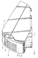
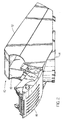
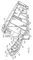
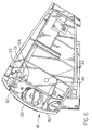
- Figures 1 and 2 comprise isometric views of a low cost small foot print thermal printer 10 in accordance with the invention respectively showing the printer door subassembly closed and open.
- Printer 10 is suitable for printing receipts, labels, and the like in various applications such as point-of-sale (POS) situations.
- the printer 10 is primarily comprised of a main housing 12, supported on a detachable base 14, preferably at an inclined orientation, and a door subassembly 16 which is hinged for movement between the closed position shown in Figure 1 and the open position shown in Figure 2.
- a web discharge slot 18 is positioned between the door subassembly 16 and a tear bar 19 carried by housing 12.
- the printer 10 is comprised primarily of the following major components:
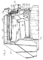
- the frame 20 defines an internal compartment 40, between side walls 41, dimensioned to accommodate a printing media, typically paper, web supply roll (not shown) so as to enable web material to be drawn from the roll by roller/platen 32 and fed past the print head 26 out through discharge slot 18.
- the roll is either loosely accommodated in compartment 40 or may be mounted for rotation about an axis defined by sidewall holes 42.
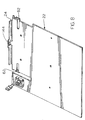
- the printed circuit board 22 shown in Figures 5 and 6 is depicted in detail in Figures 7 and 8.
- heat sink 24 is mounted on the circuit board proximate to its leading edge 52.
- the print head 26 is in turn mounted on the heat sink 24.
- the print head typically comprises a slice of ceramic material 56 carrying a plurality of heating elements 58 aligned along print line 60.
- the ends 62, 64 of the heat sink 24 are shown as extending beyond the print head 26. As will be mentioned hereinafter, these ends 62, 64 cooperate with stops 70 formed on the frame to facilitate precise positioning of the board 22 relative to the frame 20.
- the board 22 defines a mounting hole 74 positioned to receive a fastener (not shown) extending into frame hole 76.
- posts 78 align with board holes 79 and frame hole 76 aligns with board hole 74. Consequently, the board 22 is positioned with the heat sink ends 62, 64 against the stops 70 to precisely position the heat sink and print head line 60 relative to the frame 20.
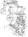
- the door subassembly 16 is comprised of a substantially arcuate panel or door 80 having outer and inner surfaces 82, 84. Moreover, the panel 80 defines an upper edge 86 and a lower edge 88. A hinge member 90 is formed adjacent the lower edge 88 and is configured to be received for rotation in recesses 92 formed by the frame 20. The door subassembly is thus able to pivot from the closed position depicted in Figure 1 to the open position depicted in Figure 2.
- the door subassembly 16 carries a short guide pin 93 which extends parallel to hinge member 90 and is positioned to be received in arcuate slot 94 formed in frame 20.
- pin 93 moves along slot 94 from its lower end to its upper end.
- recesses 92 which accommodate the hinge member 90 are configured, e.g., open at the bottom, to permit limited translation of the hinge member 90 essentially perpendicular to its axis of rotation.
- first and second spaced walls 95, 96 which define recesses 98 at their upper ends for accommodating axle 100 fixed to the drive roller/platen 32.
- Axle 100 is fixed to gear 104 which, via intermediate gears 106 is coupled to drive motor 30 carried by wall 95. Energization of the motor 30 rotates the drive roller/platen 32.
- Walls 95, 96 respectively, define arcuate slots 108 which accommodate inwardly turned forward ends 112 of springs 36.
- Each spring 36 includes a rearward end 114 which is anchored to the frame and a center portion 116 configured for mounting on frame post 118.
- Each spring 36 is configured so that it acts to bias the door subassembly 16 upward, i.e. to urge hinge member 90 to the top of recess 92.
- springs 36 urge drive roller/platen 32 upwardly against print head 26.
- the contact line between the cylindrical roller/platen 32 and the print head 26 is along print line 60.
- the web is pulled forwardly through slot 18 past tear bar 19, and beyond the print station defined by print line 60.
- the web is pinched between the spring urged roller/platen 32 and the print head 26.
- the roller/platen 32 is driven in a counterclockwise direction (as viewed in Figure 6), it will peel the web from the top of the supply roll (not shown) and advance it past the print line 60.
- the upper edge of the door subassembly 16 defines a serrated surface comprised of sharp peaks 121. These peaks are desirable to minimize contact between the back surface of the web material and surfaces of the door subassembly 16 for the purpose of enabling adhesive backed linerless material to be used.
- the outer surface 82 of door 80 is also preferably provided with peaked ribs 122.
- the door walls 95, 96 respectively carry cam elements 124 which are used for latching the door subassembly 16 in the closed position.
- the cam elements 124 each define a rearward inclined surface 126 and a forward inclined surface 128 meeting at an intermediate vertex 130.
- the cam elements 124 are positioned to cooperate with blocks 131 carried by the frame 20 for latching or detenting the door subassembly 16 in a closed position.
- the blocks 131 each define a forward inclined surface 132 and a rearward incline surface 134 meeting at an intermediate vertex 136.
- the heat sink 24 is precisely positioned relative to the frame 20 as a consequence of stops 70.
- the print head 26 and print line 60 are preferably referenced to the heat sink 24 when installed thereon.
- the roller/platen is precisely positioned relative to the door subassembly 16 by the axle 100 and recesses 98.
- one or more guide ribs 140 is provided on the door subassembly 16 projecting rearwardly from the panel inner surface 84.
- the ribs define an arcuate guide surface 142 intended to peripherally engage the web supply roll (not shown).
- the guide surface 142 helps to maintain the supply roll toward the rear of compartment 40 and guide the web material peeling from the top of the roll along a direct path past roller/platen 32.
- the ribs preferably define sharp edges 143 at their upper ends to minimize surface contact with the rear face of the web material.
- a web sensor 144 is preferably provided proximate to the forward edge of the circuit board 22 adjacent to the discharge slot 18 for sensing "top-of-form” and a "paper out” condition.
Landscapes
- Handling Of Sheets (AREA)
- Common Mechanisms (AREA)
- Electronic Switches (AREA)
- Accessory Devices And Overall Control Thereof (AREA)
Claims (10)
- Drucker, umfassend:wobei die Tür zur begrenzten manuellen Drehung um eine Gelenksachse, die im Wesentlichen parallel zum Druckkopf ausgerichtet ist, zwischen (1) einer offenen Position, die Zugang zum Abteil gewährt, und (2) einer geschlossenen Position, die das Abteil verschließt und die Tür mit dem Rahmen verriegelt, zu drehen; wobei die Tür-Befestigung begrenzte Translationsbewegung im Wesentlichen senkrecht zur Gelenksachse zulässt, undeinen Rahmen, der ein Abteil zum Unterbringen einer Druckmedium-Vorratsrolle definiert;einen Druckkopf, der fix in Bezug auf den Rahmen montiert ist;eine Tür;eine von der Tür getragene Antriebswalze;einen Motor, der auf der Tür montiert ist, um die Antriebswalze zu drehen;ein Tür-Sperrelement, das von der Tür getragen wird;ein Rahmen-Sperrelement, das vom Rahmen getragen wird;
zumindest eine Feder, die auf die Tür wirkt, um die begrenzte Translationsbewegung der Tür (1) weg vom Druckkopf zuzulassen, um es zu ermöglichen, dass sich die Tür aus der offenen in die geschlossene Position und (2) zum Druckkopf hin bewegt, um die Walze gegen den Druckkopf zu drängen, um Druckmedium dazwischen einzuzwängen und die Tür- und Rahmen-Sperrelemente in der geschlossenen Position in Eingriff zu bringen. - Drucker nach Anspruch 1, weiters umfassend eine Platine, die auf dem Rahmen montiert ist; und worin der Druckkopf fix auf der Platine montiert ist.
- Drucker nach Anspruch 1, umfassend zumindest eine Führungsfläche auf der Tür angrenzend an das Abteil, um eine Vorratsrolle im Abteil zu positionieren.
- Vorrichtung zum Vorwärtsbewegen und Bedrucken von Bahnmaterial, umfassend:wobei die Tür-Unteranordnung in Bezug auf den Rahmen zur begrenzten manuellen Drehung um eine Gelenksachse zwischen einer offenen Position, die Zugang zum Abteil gewahrt, und einer geschlossenen Position, die die Antriebswalze unmittelbar angrenzend an den Druckkopf anordnet montiert ist; wobei der Aufbau der Tür-Unteranordnung begrenzte Translationsbewegung im Wesentlichen senkrecht zur Gelenksachse zulässt, undeinen Rahmen, der ein Abteil zum Unterbringen einer Bahnmaterial-Rolle definiert;ein Rahmen-Sperrelement, das vom Rahmen getragen wird;einen Druckkopf, der fix in Bezug auf den Rahmen montiert ist;eine Tür-Unteranordnung, die eine zum Rotieren montierte Antriebswalze und einen Motor zum Drehen der Antriebswalze umfasst;ein Tür-Sperrelement, das von der Tür-Unteranordnung getragen wird;
zumindest eine Feder, die in der geschlossenen Position auf die Tür-Unteranordnung wirkt, um (1) die Antriebswalze gegen den Druckkopf zu drängen, um einen Abschnitt des Bahnmaterials dazwischen einzuzwängen, um es am Druckkopf vorbei zu fördern, und (2) die Tür- und Rahmen-Sperrelemente gemeinsam zu drängen, um die Tür-Unteranordnung mit dem Rahmen zu verriegeln. - Vorrichtung nach Anspruch 4, worin die Tür-Unteranordnung weiters einen Motor umfasst, der mit Energie beaufschlagt werden kann, um die Antriebswalze zu drehen.
- Vorrichtung nach Anspruch 4, die eine Platine umfasst, die auf dem Rahmen montiert ist; und worin der Druckkopf angrenzend an eine Kante davon fix auf der Platine montiert ist.
- Vorrichtung nach Anspruch 6, weiters umfassend einen Bahnsensor, der nahe der einen Kante auf der Platine montiert ist.
- Vorrichtung nach Anspruch 4, die umfasst:eine auf dem Rahmen montierte Platine;einen Kühlkörper, der entlang einer Kante der Platine montiert ist; und worinder Druckkopf am Kühlkörper befestigt ist.
- Vorrichtung nach Anspruch 4, worin die Sperre, um die Tür-Unteranordnung in der geschlossenen Position zu halten,
ein Sperrelement, das auf dem Rahmen definiert ist, und ein Nockenelement umfasst, das von der Tür-Unteranordnung getragen wird, wobei das Sperr- und das Nockenelement jeweils komplementäre Oberflächen definieren, die (1) es ermöglichen, dass sich das Nockenelement am Sperrelement vorbei bewegt, wenn die Tür-Unteranordnung in die geschlossene Position gedreht wird, und (2) das Nockenelement daran hindern, sich aus der geschlossenen Position in die entgegengesetzte Richtung zu drehen. - Vorrichtung nach Anspruch 8, worin die Tür-Unteranordnung eine Anschlagfläche zum Angreifen am Kühlkörper definiert, um die Antriebswalze präzise in Bezug auf den Druckkopf zu positionieren, wenn sich die Tür-Unteranordnung in der geschlossenen Position befindet.
Applications Claiming Priority (3)
| Application Number | Priority Date | Filing Date | Title |
|---|---|---|---|
| US644495P | 1995-11-13 | 1995-11-13 | |
| US6444P | 1995-11-13 | ||
| PCT/US1996/017933 WO1997018087A1 (en) | 1995-11-13 | 1996-11-12 | Thermal printer with spring biased drive roller/platen |
Publications (3)
| Publication Number | Publication Date |
|---|---|
| EP0902744A4 EP0902744A4 (de) | 1999-03-24 |
| EP0902744A1 EP0902744A1 (de) | 1999-03-24 |
| EP0902744B1 true EP0902744B1 (de) | 2002-03-13 |
Family
ID=21720920
Family Applications (1)
| Application Number | Title | Priority Date | Filing Date |
|---|---|---|---|
| EP96941330A Expired - Lifetime EP0902744B1 (de) | 1995-11-13 | 1996-11-12 | Thermischer drucker mit unter federspannung stehender rolle schreibwalze |
Country Status (6)
| Country | Link |
|---|---|
| US (1) | US5791796A (de) |
| EP (1) | EP0902744B1 (de) |
| AU (1) | AU700935B2 (de) |
| CA (1) | CA2239903C (de) |
| DE (1) | DE69619870T2 (de) |
| WO (1) | WO1997018087A1 (de) |
Families Citing this family (23)
| Publication number | Priority date | Publication date | Assignee | Title |
|---|---|---|---|---|
| US5833377A (en) * | 1996-05-10 | 1998-11-10 | Monarch Marking Systems, Inc. | Core, spindle and combination thereof |
| FR2763887B1 (fr) * | 1997-05-30 | 1999-08-13 | Ascom Monetel Sa | Imprimante thermique a remplacement aise de papier d'impression |
| US5887999A (en) * | 1997-10-06 | 1999-03-30 | Axiohm Ipb Inc. | Paper loading mechanism |
| US6155731A (en) * | 1997-10-17 | 2000-12-05 | Axiohm Transaction Solutions, Inc. | Printing apparatus with cover actuated drive source |
| US6102590A (en) * | 1998-03-12 | 2000-08-15 | International Business Machines Corporation | Cover-platen opening mechanism |
| EP0990533B1 (de) * | 1998-10-02 | 2004-12-22 | Seiko Epson Corporation | Drucker und Verfahren zu dessen Steuerung |
| JP2000168194A (ja) * | 1998-12-08 | 2000-06-20 | Seiko Epson Corp | 電子機器及びプリンタ |
| FR2790998B1 (fr) * | 1999-03-16 | 2001-04-20 | Sagem | Machine de bureau a imprimante a papier en rouleau |
| US6406200B2 (en) | 1999-07-30 | 2002-06-18 | Inovise Medical, Inc. | Printer assembly with lateral and longitudinal self-alignment |
| US6241407B1 (en) * | 1999-09-16 | 2001-06-05 | Monarch Marking Systems, Inc. | Portable printer |
| US6494631B1 (en) * | 2000-09-29 | 2002-12-17 | Z.I.H. Corp. | Printer with ribbon fold out mechanism |
| US6604876B2 (en) * | 2000-09-29 | 2003-08-12 | Zih Corp. | System for dissipating electrostatic charge in a printer |
| DE60300868T2 (de) | 2002-01-18 | 2006-05-11 | Seiko Epson Corp. | Drucker |
| DE10215122B4 (de) * | 2002-04-05 | 2005-03-03 | Siemens Ag | Fahrtschreiber mit einem quaderförmigen Gehäuse und einer Druckvorrichtung |
| JP2004074622A (ja) * | 2002-08-20 | 2004-03-11 | Fujitsu Component Ltd | ロール紙プリンタ |
| KR100557013B1 (ko) * | 2004-04-16 | 2006-03-03 | 주식회사 빅솔론 | 회전식 플라텐을 구비한 도트 프린터 |
| KR101079580B1 (ko) * | 2007-02-15 | 2011-11-03 | 삼성전자주식회사 | 도어의 회동속도를 조절할 수 있는 도어개폐유닛 및 이를포함하는 화상형성장치 |
| JP5082749B2 (ja) | 2007-10-15 | 2012-11-28 | セイコーエプソン株式会社 | プリンタ |
| US8454251B2 (en) * | 2008-09-25 | 2013-06-04 | Videojet Technologies Inc. | Printer bracket |
| US8177156B1 (en) * | 2009-11-23 | 2012-05-15 | Rinne Rhett L | Sheet roll dispenser |
| US9493017B2 (en) | 2015-02-13 | 2016-11-15 | Zih Corp. | Modular print drive assembly and platen assembly |
| WO2018048397A1 (en) * | 2016-09-07 | 2018-03-15 | Hewlett-Packard Development Company, L.P. | Latches |
| US20220063314A1 (en) * | 2019-01-09 | 2022-03-03 | Hewlett-Packard Development Company, L.P. | Cylindrical printing devices |
Family Cites Families (15)
| Publication number | Priority date | Publication date | Assignee | Title |
|---|---|---|---|---|
| US3851942A (en) * | 1973-12-03 | 1974-12-03 | Reed Ind Inc | Meter box with vault latch |
| JPS56167484A (en) * | 1980-05-30 | 1981-12-23 | Canon Inc | Printer |
| US4614949A (en) * | 1983-10-20 | 1986-09-30 | Ricoh Company, Ltd. | Transfer-type thermal printer |
| JPS61132362A (ja) * | 1984-11-30 | 1986-06-19 | Toshiba Corp | 感熱転写記録方法 |
| US4838713A (en) * | 1985-08-20 | 1989-06-13 | Sanyo Electric Ltd. | Thermal transfer printer head position homing mechanism |
| JPS62164551A (ja) * | 1986-01-17 | 1987-07-21 | Ricoh Co Ltd | ライン熱転写プリンタ |
| JPH07108591B2 (ja) * | 1986-06-20 | 1995-11-22 | ソニー株式会社 | プリンタ |
| JPS63306065A (ja) * | 1987-06-05 | 1988-12-14 | Minolta Camera Co Ltd | 熱転写プリンタ |
| JPH01269557A (ja) * | 1988-04-20 | 1989-10-27 | Fuji Photo Film Co Ltd | サーマルプリンタ装置 |
| KR0133931B1 (ko) * | 1988-11-30 | 1998-04-20 | 오가 노리오 | 프린터 |
| US5030968A (en) * | 1988-12-30 | 1991-07-09 | Benson James A | Recorder enclosure with printhead and roller attached to pivotable covers |
| JP3050622B2 (ja) * | 1991-03-27 | 2000-06-12 | シャープ株式会社 | 印字装置 |
| DE4224533A1 (de) * | 1991-07-25 | 1993-01-28 | Kanzaki Paper Mfg Co Ltd | Thermo-drucker |
| US5447380A (en) * | 1992-06-01 | 1995-09-05 | Nai Technologies, Inc. | Thermal printer |
| JP3153103B2 (ja) * | 1995-05-26 | 2001-04-03 | 株式会社沖データ | 印刷ヘッドの位置決め装置及びそれを備えた印刷装置 |
-
1996
- 1996-11-12 AU AU10507/97A patent/AU700935B2/en not_active Ceased
- 1996-11-12 CA CA002239903A patent/CA2239903C/en not_active Expired - Fee Related
- 1996-11-12 DE DE69619870T patent/DE69619870T2/de not_active Expired - Fee Related
- 1996-11-12 EP EP96941330A patent/EP0902744B1/de not_active Expired - Lifetime
- 1996-11-12 WO PCT/US1996/017933 patent/WO1997018087A1/en not_active Ceased
- 1996-11-12 US US08/747,332 patent/US5791796A/en not_active Expired - Lifetime
Also Published As
| Publication number | Publication date |
|---|---|
| AU700935B2 (en) | 1999-01-14 |
| AU1050797A (en) | 1997-06-05 |
| WO1997018087A1 (en) | 1997-05-22 |
| EP0902744A4 (de) | 1999-03-24 |
| EP0902744A1 (de) | 1999-03-24 |
| DE69619870D1 (de) | 2002-04-18 |
| CA2239903C (en) | 2002-10-29 |
| DE69619870T2 (de) | 2002-10-31 |
| US5791796A (en) | 1998-08-11 |
| CA2239903A1 (en) | 1997-05-22 |
Similar Documents
| Publication | Publication Date | Title |
|---|---|---|
| EP0902744B1 (de) | Thermischer drucker mit unter federspannung stehender rolle schreibwalze | |
| US6604874B2 (en) | Printer with multifunctional lever actuated mechanism | |
| TW520326B (en) | Tape printing device | |
| EP0661163A2 (de) | Etikettendrucker und Kassette mit Druckband und Farbband zur Verwendung darin | |
| US5049228A (en) | Desk top type label printer | |
| EP0764542B1 (de) | Druckvorrichtung mit automatischem Schneider | |
| US6296032B1 (en) | Laminator printer | |
| EP2093071B1 (de) | Tragbare Drucker und Verfahren | |
| US6732619B2 (en) | Cutter mechanism | |
| KR900005033B1 (ko) | 전자식 핸드 라벨러 | |
| US20140210936A1 (en) | Portable printer and methods | |
| JP2002144657A (ja) | プリンタ | |
| US4552610A (en) | Automatic label winding and charging device for printers | |
| WO1995032869A1 (en) | Thermal printer | |
| JP2945212B2 (ja) | ラベル剥離装置 | |
| JP3005172B2 (ja) | プリンタ | |
| JP3410817B2 (ja) | プリンタ装置 | |
| JP2715099B2 (ja) | 値札用サーマルプリンタの印字圧切換え機構 | |
| JPH04185368A (ja) | 用紙送り装置 | |
| JPH06278733A (ja) | 卓上型ラベル印刷機 | |
| JPH0767815B2 (ja) | 電子式ラベラーのサーマルヘッド装置 | |
| JPH0640447A (ja) | 電子式ハンドラベラ | |
| JPH09123495A (ja) | 熱転写印字装置 | |
| JPH03187828A (ja) | 電子式ラベラー | |
| HK1014249B (en) | A printing apparatus having an auto cutter |
Legal Events
| Date | Code | Title | Description |
|---|---|---|---|
| PUAI | Public reference made under article 153(3) epc to a published international application that has entered the european phase |
Free format text: ORIGINAL CODE: 0009012 |
|
| 17P | Request for examination filed |
Effective date: 19980612 |
|
| A4 | Supplementary search report drawn up and despatched |
Effective date: 19981209 |
|
| AK | Designated contracting states |
Kind code of ref document: A4 Designated state(s): AT BE CH DE DK ES FI FR GB GR IE IT LI LU MC NL PT SE Kind code of ref document: A1 Designated state(s): DE FR |
|
| GRAG | Despatch of communication of intention to grant |
Free format text: ORIGINAL CODE: EPIDOS AGRA |
|
| 17Q | First examination report despatched |
Effective date: 20001026 |
|
| GRAG | Despatch of communication of intention to grant |
Free format text: ORIGINAL CODE: EPIDOS AGRA |
|
| GRAH | Despatch of communication of intention to grant a patent |
Free format text: ORIGINAL CODE: EPIDOS IGRA |
|
| GRAH | Despatch of communication of intention to grant a patent |
Free format text: ORIGINAL CODE: EPIDOS IGRA |
|
| RBV | Designated contracting states (corrected) |
Designated state(s): DE FR |
|
| RAP1 | Party data changed (applicant data changed or rights of an application transferred) |
Owner name: ZIH CORPORATION |
|
| GRAA | (expected) grant |
Free format text: ORIGINAL CODE: 0009210 |
|
| RIN1 | Information on inventor provided before grant (corrected) |
Inventor name: LODWIG, DEAN, H. Inventor name: BRYER, PHILIP, S. Inventor name: GUSTAVSSON, VIGO, H. |
|
| AK | Designated contracting states |
Kind code of ref document: B1 Designated state(s): DE FR |
|
| REF | Corresponds to: |
Ref document number: 69619870 Country of ref document: DE Date of ref document: 20020418 |
|
| ET | Fr: translation filed | ||
| PLBE | No opposition filed within time limit |
Free format text: ORIGINAL CODE: 0009261 |
|
| STAA | Information on the status of an ep patent application or granted ep patent |
Free format text: STATUS: NO OPPOSITION FILED WITHIN TIME LIMIT |
|
| 26N | No opposition filed |
Effective date: 20021216 |
|
| PG25 | Lapsed in a contracting state [announced via postgrant information from national office to epo] |
Ref country code: DE Free format text: LAPSE BECAUSE OF NON-PAYMENT OF DUE FEES Effective date: 20030603 |
|
| PG25 | Lapsed in a contracting state [announced via postgrant information from national office to epo] |
Ref country code: FR Free format text: LAPSE BECAUSE OF NON-PAYMENT OF DUE FEES Effective date: 20030731 |
|
| REG | Reference to a national code |
Ref country code: FR Ref legal event code: ST |