EP0902399B1 - Speichervorrichtung für kartenförmige Datenträger - Google Patents
Speichervorrichtung für kartenförmige Datenträger Download PDFInfo
- Publication number
- EP0902399B1 EP0902399B1 EP97115156A EP97115156A EP0902399B1 EP 0902399 B1 EP0902399 B1 EP 0902399B1 EP 97115156 A EP97115156 A EP 97115156A EP 97115156 A EP97115156 A EP 97115156A EP 0902399 B1 EP0902399 B1 EP 0902399B1
- Authority
- EP
- European Patent Office
- Prior art keywords
- roller
- magazine
- storage arrangement
- arrangement according
- card
- Prior art date
- Legal status (The legal status is an assumption and is not a legal conclusion. Google has not performed a legal analysis and makes no representation as to the accuracy of the status listed.)
- Expired - Lifetime
Links
Images


Classifications
-
- G—PHYSICS
- G07—CHECKING-DEVICES
- G07B—TICKET-ISSUING APPARATUS; FARE-REGISTERING APPARATUS; FRANKING APPARATUS
- G07B3/00—Machines for issuing preprinted tickets
- G07B3/04—Machines for issuing preprinted tickets from a stack
-
- Y—GENERAL TAGGING OF NEW TECHNOLOGICAL DEVELOPMENTS; GENERAL TAGGING OF CROSS-SECTIONAL TECHNOLOGIES SPANNING OVER SEVERAL SECTIONS OF THE IPC; TECHNICAL SUBJECTS COVERED BY FORMER USPC CROSS-REFERENCE ART COLLECTIONS [XRACs] AND DIGESTS
- Y10—TECHNICAL SUBJECTS COVERED BY FORMER USPC
- Y10S—TECHNICAL SUBJECTS COVERED BY FORMER USPC CROSS-REFERENCE ART COLLECTIONS [XRACs] AND DIGESTS
- Y10S414/00—Material or article handling
- Y10S414/10—Associated with forming or dispersing groups of intersupporting articles, e.g. stacking patterns
- Y10S414/102—Associated with forming or dispersing groups of intersupporting articles, e.g. stacking patterns including support for group
- Y10S414/103—Vertically shiftable
Definitions
- the invention relates to a storage device for card-shaped data carriers with at least one memory in which the card-shaped data carrier a vertically movable support base are arranged one on top of the other and from which the top data carrier by a separating roller laterally removable through an output slot and a drive roller for transfer can be fed to downstream processing and / or output.
- Such storage devices for card-shaped data carriers are in different Embodiments, for example for issuing user authorization cards known for parking garages.
- European Patent application 96 110 551.7 is a self-replenishing storage device described for card-shaped data carriers that consist of several memories exists and an automatic filling and / or emptying of all storage allows.
- a device of this type is also disclosed in DE 19 605 106.
- the invention has for its object a storage device to provide as known known type with at least one memory, which is structurally simple and therefore inexpensive to manufacture and has a basic structure owns, which can be expanded in different expansion stages and one has high reliability, so that the storage device to different Requirements can be adjusted.
- the support base is arranged on a carriage which vertically movable on a magazine carrier and by a motor an endless flexible traction element can be driven, which has two outside of the range of movement of the slide arranged on the magazine carrier Deflection rollers is guided and two freely rotatably mounted on the carriage Drive rollers of the same diameter in the same direction that drives are interconnected by a differential gear.
- the endless flexible traction element guided over the deflection rollers for example A timing belt, or chain, is driven by the engine in one of two possible directions of rotation driven and in turn drives with each Run on one of the two drive rollers, which are freely rotatable on the slide are. Since these drive rollers have the same diameter and the same If the direction of rotation were driven, there would be no movement of the slide. This is achieved only in that the two drive rollers by a Differential gears are interconnected. This differential gear causes the twist angle of the two drive rollers despite their being the same Diameter is different. Because the two strands of the flexible tension element is forced to move at the same speed this results in a relative movement of the slide to the flexible tension element and thus forced to the magazine carrier. The direction and size of this Relative movement is based on the direction of rotation of the motor and the difference in Angle of rotation of the drive rollers dependent, so that they by training of the respective differential gear can be determined.
- the differential gear by two through an endless flexible connecting element connected differential roles formed, each with a drive role non-rotatably arranged on a connecting shaft and with different Diameter are formed. Due to the different diameters the differential rollers and their connection by means of an endless flexible Traction element, in particular a toothed belt or a chain, is a different angle of rotation is imposed on the drive rollers causes the carriage supporting the drive rollers to perform a compensatory movement in the longitudinal direction of the circumferential flexible tension element, i.e. in Longitudinal direction of the magazine carrier on which the guide rollers for the flexible tension element are stored.
- This compensatory movement depends on Difference in the diameter of the differential rollers and results in a self-locking Drive for the supporting floor, which is the linear processing large Forces and a very precise movement of the tray over its entire length Movement range allows, as is the case for the controlled feeding of the individual card-shaped data carriers are required for the magazine output slot is.
- these are flexible Tension element and the flexible connecting element as a toothed belt and the Drive rollers and differential rollers are designed as toothed belt rollers. As a result, there is a slip between with little technical effort this drive parts excluded.
- the invention proposes the carriage by means of rollers to run in the longitudinal direction of the magazine carrier, so that a cover-free Movement of the carriage is achieved.
- the memory consists of the Magazine carrier and an interchangeable magazine that holds the card-shaped data carriers with a fixed magazine bottom and can be fixed on the magazine carrier by means of two support arms. This results in a structurally simple structure and a simple replacement of each Memory.
- the invention also proposes using the magazine base to provide at least one passage opening for the supporting floor.
- This Training enables a filled magazine in which the card-shaped Data carriers lie on the magazine base, to be attached to the magazine carrier, the supporting floor is in its lowest position, the one below of the magazine base attached to the magazine carrier.
- Raising the support floor passes through the passage opening in the magazine bottom and takes over the card-shaped data carriers that thus lifted off the magazine bottom and one after the other as required Output slot to be performed.
- the magazine is to prevent during the operation of the storage device according to a further feature of the invention with in side recesses protruding wall parts. These wall parts prevent the magazine from being removed from the magazine carrier if the Tragêt in the area of the magazine, i.e. is in his work area.
- the magazine is included a C-shaped cross-section, its opposing Each leg in one of two opposite recesses protrude from the supporting floor. This results in a particularly simple design of the magazine, which is only in the lowest end position of the tray is removable from the magazine carrier.
- the magazine is on it Sloping underside and correspondingly sloping downwards Support arms attached, which are attached to the magazine carrier.
- the magazine by means of a Magazine carrier arranged tab set with a in a bolt opening engaging locking bolt is provided.
- the Motor housing around a parallel, but eccentric to the motor axis Swivel axis is pivotally mounted on the magazine carrier.
- the motor housing of the selection motor is according to the invention via its as Separating output pulley and above the top one card-shaped data carrier can be pivoted into its operative position through the supporting base, so that then always a card-shaped data carrier from the side Output slot of the magazine can be output if the respective top card-shaped data carrier in its output position in front of the Output slot is transferred through the tray.
- the invention is monitored by a switch that by the pivoting movement the motor housing is actuated, is a targeted output of the top card-shaped data carrier possible as soon as this brought into its dispensing position by moving the support base has been.
- the transport roller To also remove the magazine from the side of the output slot issued data medium for the purpose of forwarding to a reworked processing and / or to simplify it for output to a user the transport roller according to a further feature of the invention laterally above the output slot of the magazine and arranged by a Transport motor drivable, the one via an intermediate gear Retaining roller arranged below the transport roller in the same direction of rotation how the feed roller drives, being between this retention roller and the transport roller is formed a gap which is larger than the thickness and is less than twice the thickness of the card-shaped data carrier.
- This inventive design of the separation device downstream Transport device ensures on the one hand that only the top card-shaped data carrier is pulled out of the magazine as a especially entrained by friction between the data carriers additional data carriers through the in the opposite transport direction Transport roller driven retention roller is returned to the magazine.
- this basic design of the transport device enables that according to a further feature of the invention that of transport and retention role a puller roller pair is subordinated to an existing roller pair, the one from the idler gear in the same direction as the transport roller driven roller and a freely rotatable, against the driven There is a counter roller pressed by spring force.
- the the Card-shaped to be fed or issued for further processing Data carrier is thus captured by two pairs of roles, which is a very high functional reliability results.
- the transport roller in two directions of rotation can be driven and with one arranged above Pressure roller cooperates, the gap formed by these rollers card-shaped data carrier from a neighboring memory for distribution are supplied, the gap formed by these rollers Guide plate for card-shaped coming from a neighboring store Disk is assigned.
- each adjacent memory to each other in height by the distance between that through the Transport roller and the retaining roller and the gap formed by the Transport roller and the pressure roller formed gap. hereby there is an essentially straight course for the transport of the disk coming in the rear storage.
- a guide plate is arranged above the guide plate, the card-shaped one Data carrier of the neighboring storage through the transport roller and Pressure roller feeds formed gap.
- the invention proposes the selection engine, the To arrange the transport motor and all associated rollers on a support housing, that above the interchangeable magazine and in front of the associated one Magazine carrier is arranged on the magazine carrier. This gives a particularly simple construction for the storage device according to the invention.
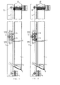
- the storage device shown in Figures 1 to 3 only includes a memory, which in turn consists of an interchangeable magazine 1 and a magazine carrier 2 and the associated facilities for storage and the transport of the card-shaped data carriers stored in the magazine 1 D and for the separation and removal of the individual Disk D exists.
- magazine 1 there are data carriers of the same thickness stored, for example EC cards, chip cards, transponder cards and Magnetic cards.
- card-shaped data carriers D of different types and Thickness must be saved for each card type and card thickness Magazine 1 can be arranged.
- the structure and mode of operation of these existing storage from magazine 1 and magazine carrier 2 is identical, so that based on that shown in Figures 1 to 3 Embodiment only such a memory is described.
- the magazine 1 shows a C-shaped cross section, as can be seen from FIGS. 8 and 9.
- the front 1a forming the web of this C-shaped cross section itself forming a right angle from the parallel to each other extending legs of the C-shaped cross section formed side walls 1b of magazine 1, which at the end turned at a right angle are and form opposing legs 1c.
- the side walls 1b according to FIG. 10 form cover strips 1d bent.
- the magazine 1 is provided with an output slot 1e.
- the lower end of the magazine 1 is chamfered.
- the magazine 1 which at Exemplary embodiment by two strip-shaped supports on the side walls 1b is formed, which has a through opening for the Form tray 3.
- the card-shaped data carriers D lie on when a filled magazine 1 is attached to the magazine carrier 2.
- the magazine carrier 2 which is in the embodiment is formed with a U-shaped cross section, in its lower Provide area with two inclined support arms 2a, one have an angular cross-section, the vertical leg of the lateral Management of the magazine 1 and its horizontal leg to support the Magazine 1 serves.
- a filled magazine 1 is from bottom to top of the Magazine carrier 2 attached, guided between the support arms 2a and then locked by a tab 2b arranged on the magazine carrier 2, with a locking bolt engaging in a locking opening of the magazine 1 2c is provided.
- a vertically movable support base 3 is on the magazine support 2 movably guided, an embodiment of which is best shown in the figures 8 and 9 can be seen.
- This support floor 3 is on a slide 4 arranged, which consists of two mutually parallel slide walls 4a and 4b. While the front carriage wall 4a integrally with the Support base 3 is formed by an angle plate, it is in the rear slide wall 4b around a separate sheet metal part, which according to FIG by means of two bolts 4c with the front slide wall 4a connected is.
- the support base 3 shown in a top view in FIG. 9 is forked with two bottom halves 3a running at a distance from one another.
- each Bottom half 3a is provided with a lateral recess 3b, in each a leg 1c of the magazine 1 protrudes, as can be seen in FIG. This ensures that the magazine 1 is not from Magazine carrier 2 can be removed as long as the base 3 in his work area.
- the carriage 4 is driven by a at the lower end of the Magazine carrier 2 arranged motor 6 via a flexible tension element, the is designed as a toothed belt 7 in the embodiment, but also as V-belt or chain can be executed.
- This toothed belt 7 is over two arranged outside the range of motion 4 of the magazine carrier 2 Deflection rollers 8a and 8b, of which the lower deflection roller 8a on the Drive shaft of the motor 6 sits and thus from this motor 6, namely in is drivable in both directions.
- each drive roller 9 is two laterally offset guide rollers 10 assigned, which are freely rotatable on a Axis 11 are mounted, on which the rollers 5 are freely rotatable ( Figure 6).
- the drive rollers 9 are non-rotatable Arranged on a shaft 12, which to the rear from the rear sled wall 4b of the carriage 4 protrudes, each on this protruding end Shaft 12 each have a differential roller 13a or 13b rotatably attached.
- the differential rollers 13a and 13b have a different one Diameter or a different number of teeth.
- the drive rollers 9 with 21 teeth
- the differential roller 13a also with Provide 21 teeth
- the differential roller 13b with 18 teeth.
- the Differential rollers 13a and 13b are endlessly flexible with each other Connection element connected, which in turn in the embodiment as endless toothed belt 14 is executed (Fig. 7). The better clarity because of Figures 4 to 6 and 8, both the toothed belt 7 and the toothed belt 14 has been omitted. 2, the toothed belt 7 only indicated by dash-dotted lines; the timing belt 14 was again omitted.
- the drive rollers 9 of the Slide 4 with the same direction of rotation and with the same angular velocity driven.
- these drive rollers 9 are non-rotatable via the shafts 12 are connected to the differential rollers 13a and 13b, respectively have different number of teeth, depending on the direction of rotation of the Timing belt 7 a relative movement of the carriage 4 in the longitudinal direction of the Magazine carrier 2, since that of the differential rollers 13a and 13b different angles of rotation imposed by a relative movement of the carriage 4 compared to the rotating toothed belt 7 Need to become.
- the differential gear formed in this way is for the circumferential toothed belt 7 self-locking and enables the rulers Processing large forces.
- the ratio of the number of teeth of the differential rollers 13a and 13b gives the path for the movement of the carriage 4 relative to the Magazine carrier 2 and thus for the movement of the carriage 4 arranged tray 3.
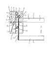
- a selection motor 15 is provided, the drive roller as Separating roller 15a is formed on the top of each top card-shaped data carrier D acts in magazine 1.
- the Motor housing of the selection motor 15 is parallel, however Eccentric pivot axis 15b pivotable mounted on the magazine carrier 2 and provided with a switching arm 15c, which with a switch 16 cooperates.
- the pair of rollers consisting of transport roller 17 and retaining roller 18 in the exemplary embodiment, a pair of puller rollers arranged from a driven by the intermediate gear 20 in the same direction with the transport roller 17 Roller 21 and a freely rotatable, against the driven roller 21st there is a counter roller 22 pressed by spring force.
- the transport roller 17 can of the transport motor 19 in both directions of rotation are driven not only from the output slot 1e of the associated magazine 1 coming data carrier D for further processing or the output, but also from an upstream To transport magazine coming data carriers.
- the gap formed by these rollers 17 and 23 is one Assigned guide plate 24 on which the magazine 1 above the Separation roller 15a passing data carrier D lie on.
- the roller 21 driven in the same direction with the transport roller 17 is at Embodiment assigned a pressure roller 25. To use this enable, has the retaining roller 18 when driving the transport roller in Clockwise a freewheel.
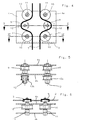
- the storage device comprises a plurality of memories, as shown in FIG. 11 is shown based on two memories, are each adjacent memories to each other in height by the distance between that through the Transport roller 17 and the retaining roller 18 formed by the gap the transport roller 18 and the pressure roller 23 formed gap.
- the magazine 1 of the left-hand memory deducted card-shaped data carrier D the leave the transport device formed by the transport motor 19, reliably on the top of the guide plate 24 of the right memory arrive and here between the transport roller 17 and the pressure roller 23 formed gap are fed.
- the transport device of the left memory card-shaped data carrier D are delivered, the if they already come from a further arranged storage, they occur from the gap formed between the roller 21 and the pressure roller 25.
- a baffle 26 is provided, one funnel-shaped supply of this data carrier D to the associated gap causes.
- Figures 10 and 11 finally show that in front of the magazine carrier 2 Support housing 27 is arranged on which the selection motor 15, the Transport motor 19 and all associated roles are arranged. It This also results in a structurally simple design for this assembly Unit.
Landscapes
- Physics & Mathematics (AREA)
- General Physics & Mathematics (AREA)
- Conveying Record Carriers (AREA)
- Sheets, Magazines, And Separation Thereof (AREA)
- Credit Cards Or The Like (AREA)
Description
- Fig. 1
- eine Seitenansicht eines Speichers,
- Fig. 2
- einen senkrechten Längsschnitt durch den Speicher gemäß der Abbildung Fig.1,
- Fig. 3
- eine rückwärtige Ansicht des Speichers gemäß der Fig. 1 und 2,
- Fig. 4
- eine vergrößerte Darstellung des Schlittens gemäß der Schnittlinie IV - IV in Fig. 2,
- Fig. 5
- einen Querschnitt durch den Schlitten gemäß der Schnittlinie V - V in Fig. 4,
- Fig. 6
- einen weiteren Querschnitt durch den Schlitten gemäß der Schnittlinie VI - VI in Fig. 4,
- Fig. 7
- eine vergrößerte Darstellung des Schlittens gemäß der Schnittlinie VII - VII in Fig. 2,
- Fig. 8
- eine Seitenansicht des in der unteren Endstellung befindlichen Schlittens und des unteren Endes des Magazins,
- Fig. 9
- einen waagerechten Schnitt durch das Magazin gemäß der Schnittlinie IX - IX in Fig. 8 und eine Draufsicht auf den Trag- und Magazinboden,
- Fig. 10
- eine schematische Frontansicht des oberen Endes eines Magazins sowie der Vereinzelungs- und Transportvorrichtung und
- Fig. 11
- eine der Fig. 10 entsprechende Frontansicht zweier nebeneinanderliegender Speicher.
- D
- kartenförmiger Datenträger
- 1
- Magazin
- 1 a
- Frontseite
- 1b
- Seitenwand
- 1c
- Schenkel
- 1d
- Deckelstreifen
- 1e
- Ausgabeschlitz
- 1f
- Magazinboden
- 2
- Magazinträger
- 2a
- Tragarm
- 2b
- Lasche
- 2c
- Riegelbolzen
- 2d
- Führungsnut
- 3
- Tragboden
- 3a
- Bodenhälfte
- 3b
- Aussparung
- 4
- Schlitten
- 4a
- vordere Schlittenwand
- 4b
- hintere Schlittenwand
- 4c
- Schraubenbolzen
- 5
- Laufrolle
- 6
- Motor
- 7
- Zahnriemen (biegsames Zugelement)
- 8a
- Umlenkrolle
- 8b
- Umlenkrolle
- 9
- Antriebsrolle
- 10
- Führungsrolle
- 11
- Achse
- 12
- Welle
- 13a
- Differenzrolle
- 13b
- Differenzrolle
- 14
- Zahnriemen
(biegsames Verbindungselement) - 15
- Selektionsmotor
- 15a
- Vereinzelungsrolle
- 15b
- Schwenkachse
- 15c
- Schaltarm
- 16
- Schalter
- 17
- Transportrolle
- 18
- Rückhalterolle
- 19
- Transportmotor
- 20
- Zwischenzahnrad
- 21
- Rolle
- 22
- Gegenrolle
- 23
- Andrückrolle
- 24
- Führungsblech
- 25
- Andrückrolle
- 26
- Leitblech
- 27
- Traggehäuse
- 28
- Überwachungselement
Claims (20)
- Speichervorrichtung für kartenförmige Datenträger mit mindestens einem Speicher, in dem die kartenförmigen Datenträger (D) auf einem höhenbeweglichen Tragboden (3) aufeinanderliegend angeordnet sind und auf dem der jeweils oberste Datenträger (D) durch eine Vereinzelungsrolle (15a) seitlich durch einen Ausgabeschlitz (1e) abziehbar und einer Transportrolle (17) zur Weitergabe an eine nachgeschaltete Verarbeitung und/oder der Ausgabe zuführbar ist,
dadurch gekennzeichnet, daß der Tragboden (3) an einem Schlitten (4) angeordnet ist, der höhenbeweglich an einem Magazinträger (2) geführt und von einem Motor (6) durch ein endloses biegsames Zugelement (7) antreibbar ist, das über zwei außerhalb des Bewegungsbereiches des Schlittens (4) am Magazinträger (2) angeordnetet Umlenkrollen (8a, 8b) geführt ist und zwei am Schlitten (4) freidrehbar gelagerte Antriebsrollen (9) gleichen Durchmessers im gleichen Drehsinn antreibt, die miteinander durch ein Differenzgetriebe (13a, 13b, 14) verbunden sind. - Speichervorrichung nach Anspruch 1, dadurch gekennzeichnet, daß das Differenzgetriebe durch zwei durch ein endloses biegsames Verbindungselement (14) miteinander verbundene Differenzrollen (13a, 13b) gebildet ist, die gemeinsam mit jeweils einer Antriebsrolle (9) verdrehfest auf einer Welle (12) angeordnet und mit unterschiedlichem Durchmesser ausgebildet sind.
- Speichervorrichtung nach Anspruch 1 und 2, dadurch gekennzeichnet, daß das biegsame Zugelement (7) und das biegsame Verbindungselement (14) als Zahnriemen und die Antriebsrollen (9) sowie die Differenzrollen (13a, 13b) als gezahnte Riemenrollen ausgebildet sind.
- Speichervorrichtung nach einem der Ansprüche 1 bis 3, dadurch gekennzeichnet, daß das biegsame Zugelement (7) zu beiden Seiten jeder Antriebsrolle (9) über seitlich versetzt angeordnete Führungsrollen (10) geführt ist.
- Speichervorrichtung nach mindestens einem der Ansprüche 1 bis 4, dadurch gekennzeichnet, daß der Schlitten (4) mittels Laufrollen (5) in Längsrichtung des Magazinträgers (2) geführt ist.
- Speichervorrichtung nach mindestens einem der Ansprüche 1 bis 5, dadurch gekennzeichnet, daß der Speicher aus dem Magazinträger (2) und einem auswechselbaren Magazin (1) besteht, das zur Aufnahme der kartenförmigen Datenträger (D) mit einem festen Magazinboden (1f) versehen und mittels zweier Tragarme (2a) am Magazinträger (2) festlegbar ist.
- Speichervorrichtung nach Anspruch 6, dadurch gekennzeichnet, daß der Magazinboden (1f) mit einer Durchtrittsöffnung für den Tragboden (3) versehen ist.
- Speichervorrichtung nach Anspruch 6 oder 7, dadurch gekennzeichnet, daß das Magazin (1) mit in seitliche Aussparungen (3b) des Tragbodens (3) hineinragenden Wandteilen (1c) ausgebildet ist.
- Speichervorrichtung nach Anspruch 8, dadurch gekennzeichnet, daß das Magazin (1) mit einem C-förmigen Querschnitt ausgebildet ist, dessen gegeneinander weisende Schenkel (1c) in jeweils eine von zwei einander gegenüberliegende Aussparungen (3b) des Tragbodens (3) hineinragen
- Speichervorrichtung nach mindestens einem der Ansprüche 6 bis 9, dadurch gekennzeichnet, daß das Magazin (1) an seiner Unterseite abgeschrägt und auf entsprechend schräg nach unten verlaufende Tragarme (2a) aufsetzbar ist, die am Magazinträger (2) befestigt sind.
- Speichervorrichtungen nach mindestens einem der Ansprüche 6 bis 10, dadurch gekennzeichnet, daß das Magazin (1) mittels einer am Magazinträger (2) angeordneten Lasche (2b) festlegbar ist, die mit einem in eine Riegelöffnung eingreifenden Riegelbolzen (2c) versehen ist.
- Speichervorrichtung nach mindestens einem der Ansprüche 1 bis 11, dadurch gekennzeichnet, daß die auf die Oberseite des jeweils obersten kartenförmigen Datenträgers (D) einwirkende Vereinzelungsrolle (15a) als Antriebsrolle eines Selektionsmotors (15) ausgebildet ist, dessen Motorgehäuse um eine parallele, jedoch exzentrisch zur Motorachse verlaufende Schwenkachse (15b) verschwenkbar am Magazinträger (2) gelagert ist.
- Speichervorrichtung nach Anspruch 12, dadurch gekennzeichnet, daß das Motorgehäuse des Selektionsmotors (15) über seine als Vereinzelungsrolle (15a) dienende Abtriebsrolle und über den jeweils obersten kartenförmigen Datenträger D durch den Tragboden (3) in seine Wirkstellung verschwenkbar ist.
- Speichervorrichtung nach Anspruch 13, dadurch gekennzeichnet, daß die Wirkstellung der Vereinzelungsrolle (15a) durch einen Schalter (16) überwacht wird, der durch die Verschwenkbewegung des Motorgehäuses betätigt ist.
- Speichervorrichtung nach mindestens einem der Ansprüche 1 bis 14, dadurch gekennzeichnet, daß die Transportrolle (17) seitlich oberhalb des Ausgabeschlitzes (1e) jedes Magazins (1) angeordnet und durch einen Transportmotor (19) antreibbar ist, der über ein Zwischenzahnrad (20) zugleich eine unterhalb der Transportrolle (17) angeordnete Rückhalterolle (18) in derselben Drehrichtung wie die Transportrolle (17) antreibt, wobei zwischen dieser Rückhalterolle (18) und der Transportrolle (17) ein Spalt gebildet ist, der größer als die Dicke und kleiner als die zweifache Dicke der kartenförmigen Datenträger (D) ist.
- Speichervorrichtung nach Anspruch 15, dadurch gekennzeichnet, daß dem aus Transport- und Rückhalterolle (17, 18) bestehenden Rollenpaar ein Abzugsrollenpaar nachgeschaltet ist, das aus einer vom Zwischenzahnrad (20) gleichsinnig mit der Transportrolle (17) angetriebenen Rolle (21) und einer frei drehbar gelagerten, gegen die angetriebene Rolle (21) durch Federkraft angedrückten Gegenrolle (22) besteht.
- Speichervorrichtung nach Anspruch 15 oder 16, dadurch gekennzeichnet, daß die Transportrolle (17) in beiden Drehrichtungen antreibbar ist und mit einer oberhalb angeordneten Andrücksrolle (23) zusammenwirkt, wobei dem durch diese Rollen (17, 23) gebildeten Spalt ein Führungsblech (24) für aus einem benachbarten Speicher kommende kartenförmige Datenträger (D) zugeordnet ist.
- Speichervorrichtung nach Anspruch 17, dadurch gekennzeichnet, daß jeweils benachbarte Speicher zueinander in der Höhe um den Abstand zwischen dem durch die Transportrolle (17) und die Rückhalterolle (18) gebildeten Spalt und dem durch die Transportrolle (17) und die Andrücksrolle (23) gebildeten Spalt versetzt sind.
- Speichervorrichtung nach Anspruch 17 oder 18, dadurch gekennzeichnet, daß oberhalb des Führungsbleches (24) ein Leitblech (26) angeordnet ist, das kartenförmige Datenträger (D) der benachbarten Speicher dem durch die Transportrolle (17) und die Andrücksrolle (23) gebildeten Spalt zuführt.
- Speichervorrichtung nach mindestens einer der Ansprüche 1 bis 19, dadurch gekennzeichnet, daß der Selektionsmotor (15), der Transportmotor (19) und sämtliche zugehörigen Rollen an einem Traggehäuse (27) angeordnet sind, das oberhalb des auswechselbaren Magazins (1) und vor dem zugehörigen Magazinträger (2) am Magazinträger (2) angeordnet ist.
Priority Applications (4)
| Application Number | Priority Date | Filing Date | Title |
|---|---|---|---|
| EP97115156A EP0902399B1 (de) | 1997-09-02 | 1997-09-02 | Speichervorrichtung für kartenförmige Datenträger |
| AT97115156T ATE252258T1 (de) | 1997-09-02 | 1997-09-02 | Speichervorrichtung für kartenförmige datenträger |
| DE59710867T DE59710867D1 (de) | 1997-09-02 | 1997-09-02 | Speichervorrichtung für kartenförmige Datenträger |
| US09/146,916 US5904466A (en) | 1997-09-02 | 1998-09-02 | Storage device for card-shaped data carriers |
Applications Claiming Priority (1)
| Application Number | Priority Date | Filing Date | Title |
|---|---|---|---|
| EP97115156A EP0902399B1 (de) | 1997-09-02 | 1997-09-02 | Speichervorrichtung für kartenförmige Datenträger |
Publications (2)
| Publication Number | Publication Date |
|---|---|
| EP0902399A1 EP0902399A1 (de) | 1999-03-17 |
| EP0902399B1 true EP0902399B1 (de) | 2003-10-15 |
Family
ID=8227305
Family Applications (1)
| Application Number | Title | Priority Date | Filing Date |
|---|---|---|---|
| EP97115156A Expired - Lifetime EP0902399B1 (de) | 1997-09-02 | 1997-09-02 | Speichervorrichtung für kartenförmige Datenträger |
Country Status (4)
| Country | Link |
|---|---|
| US (1) | US5904466A (de) |
| EP (1) | EP0902399B1 (de) |
| AT (1) | ATE252258T1 (de) |
| DE (1) | DE59710867D1 (de) |
Families Citing this family (11)
| Publication number | Priority date | Publication date | Assignee | Title |
|---|---|---|---|---|
| US6199857B1 (en) | 1999-09-22 | 2001-03-13 | Fargo Electronics, Inc. | I. D. card output stacker |
| US6776263B2 (en) * | 2000-05-19 | 2004-08-17 | Esw-Extel Systems Wedel Gesellschaft Fuer Austruestung Mbh | Elevator system for the vertical transport of loads in an aircraft |
| EP1270488B1 (de) * | 2001-06-28 | 2008-04-02 | Inventio Ag | Aufzugsantrieb |
| US7975807B2 (en) * | 2004-01-20 | 2011-07-12 | Franklin Samuel H | Elevator climbing system |
| FR2872611B1 (fr) * | 2004-07-02 | 2006-09-29 | Thales Sa | Container empileur de cartes sans contact et module recycleur de cartes comportant un tel container |
| US8220354B2 (en) * | 2006-06-28 | 2012-07-17 | Genmark Automation, Inc. | Belt-driven robot having extended Z-axis motion |
| US8701519B2 (en) * | 2006-06-28 | 2014-04-22 | Genmark Automation, Inc. | Robot with belt-drive system |
| FI120091B (fi) * | 2006-11-10 | 2009-06-30 | Kone Corp | Vastapainoton vetopyörähissi |
| CN101315705B (zh) * | 2007-05-29 | 2012-05-02 | 上海华铭智能终端设备股份有限公司 | 一种自动售票装置 |
| ES2509352T3 (es) * | 2008-05-16 | 2014-10-17 | Thyssenkrupp Elevator Ag | Elemento de barra longitudinal para una caja de una instalación de elevador |
| CN101635064B (zh) * | 2008-12-03 | 2012-08-15 | 高新现代智能系统股份有限公司 | 一种卡片自动发放装置 |
Family Cites Families (7)
| Publication number | Priority date | Publication date | Assignee | Title |
|---|---|---|---|---|
| US651236A (en) * | 1900-01-02 | 1900-06-05 | Daniel Corcoran | Elevator. |
| US3416705A (en) * | 1965-03-02 | 1968-12-17 | Taller & Cooper Inc | Ticket dispenser with automatic feed and signal |
| FR2596552B1 (fr) * | 1986-03-25 | 1989-07-28 | Dassault Electronique | Distributeur-programmateur automatique de cartes a micro-circuit |
| US4921388A (en) * | 1986-07-07 | 1990-05-01 | Systems Mailing Research, Inc. | Envelope opener and load separator |
| US5240370A (en) * | 1990-06-01 | 1993-08-31 | Komori Corporation | Pile board inserting method and a pile board inserting machine for carrying out the same |
| JP2929806B2 (ja) * | 1991-11-12 | 1999-08-03 | 株式会社日立製作所 | 紙葉類分離繰出し装置、および、それを用いた現金自動取引装置 |
| JP2659344B2 (ja) * | 1995-02-10 | 1997-09-30 | 日本電気ロボットエンジニアリング株式会社 | 紙葉類の摩擦式供給機構 |
-
1997
- 1997-09-02 DE DE59710867T patent/DE59710867D1/de not_active Expired - Lifetime
- 1997-09-02 AT AT97115156T patent/ATE252258T1/de active
- 1997-09-02 EP EP97115156A patent/EP0902399B1/de not_active Expired - Lifetime
-
1998
- 1998-09-02 US US09/146,916 patent/US5904466A/en not_active Expired - Lifetime
Also Published As
| Publication number | Publication date |
|---|---|
| DE59710867D1 (de) | 2003-11-20 |
| EP0902399A1 (de) | 1999-03-17 |
| ATE252258T1 (de) | 2003-11-15 |
| US5904466A (en) | 1999-05-18 |
Similar Documents
| Publication | Publication Date | Title |
|---|---|---|
| EP0930248B1 (de) | Vorrichtung zum Sortieren von Stückgütern | |
| DE3013315A1 (de) | Einrichtung zum foerdern und sortieren von gegenstaenden | |
| EP0902399B1 (de) | Speichervorrichtung für kartenförmige Datenträger | |
| DE2803223A1 (de) | Verteileranlage fuer nahrungsmittelprodukte, insbesondere fuer suesswaren | |
| DE3445249A1 (de) | Vorrichtung zum transportieren von gegenstaenden | |
| DE19510649C2 (de) | Transportvorrichtung | |
| EP0564901B1 (de) | Vorschubeinrichtung für Tafeln | |
| DE1957002B2 (de) | Fördereinrichtung zum Fördern von Zigaretten | |
| DE2618439C2 (de) | Transporteinrichtung für die Auswertung von Identifizierungskarten | |
| DE3315495C2 (de) | Vorrichtung zum Lagern von Papierbogen o.dgl. | |
| EP0017014B1 (de) | Nadeldrucker mit Abschneidevorrichtung | |
| DE69325069T2 (de) | System mit einer separaten Beschickungseinheit für streifenförmiges Verpackungsmaterial | |
| DE3616252C2 (de) | ||
| CH673035A5 (de) | ||
| CH691475A5 (de) | Vorrichtung zum Füllen einer Kanne mit länglichem Querschnitt an einer Spinnereimaschine. | |
| DE69500823T2 (de) | Tragleiterführungsmechanismus für Jalousiezusammensetzungsapparat | |
| DE2245193A1 (de) | Selbsttaetige maschine zum transport von foerdergut von einer foerdereinrichtung zu einer anderen foerdereinrichtung | |
| DE3713431C2 (de) | ||
| DE4428247A1 (de) | Transportvorrichtung für textile Packungen | |
| DE3722284A1 (de) | Vorschubeinrichtung, insbesondere fuer dosenzargen | |
| WO1991000232A1 (de) | Trolleyfahrzeug zum ein- und auslagern von speicherguttragenden ladungsträgern | |
| DE69906637T2 (de) | Bandspeicher | |
| DE60309133T2 (de) | Vorrichtung zur anpassung des abstandes zwischen förderfingern an die länge des produktes | |
| DE10101563A1 (de) | Vorrichtung zur Abgabe oder Entgegennahme von Einzelblättern | |
| DE102004042594A1 (de) | Bandspeicher |
Legal Events
| Date | Code | Title | Description |
|---|---|---|---|
| PUAI | Public reference made under article 153(3) epc to a published international application that has entered the european phase |
Free format text: ORIGINAL CODE: 0009012 |
|
| 17P | Request for examination filed |
Effective date: 19980505 |
|
| AK | Designated contracting states |
Kind code of ref document: A1 Designated state(s): AT CH DE FR LI NL |
|
| AKX | Designation fees paid |
Free format text: AT CH DE FR LI NL |
|
| GRAH | Despatch of communication of intention to grant a patent |
Free format text: ORIGINAL CODE: EPIDOS IGRA |
|
| GRAS | Grant fee paid |
Free format text: ORIGINAL CODE: EPIDOSNIGR3 |
|
| GRAA | (expected) grant |
Free format text: ORIGINAL CODE: 0009210 |
|
| AK | Designated contracting states |
Kind code of ref document: B1 Designated state(s): AT CH DE FR LI NL |
|
| REG | Reference to a national code |
Ref country code: CH Ref legal event code: NV Representative=s name: DR. LUSUARDI AG Ref country code: CH Ref legal event code: EP |
|
| REF | Corresponds to: |
Ref document number: 59710867 Country of ref document: DE Date of ref document: 20031120 Kind code of ref document: P |
|
| ET | Fr: translation filed | ||
| PLBE | No opposition filed within time limit |
Free format text: ORIGINAL CODE: 0009261 |
|
| STAA | Information on the status of an ep patent application or granted ep patent |
Free format text: STATUS: NO OPPOSITION FILED WITHIN TIME LIMIT |
|
| 26N | No opposition filed |
Effective date: 20040716 |
|
| REG | Reference to a national code |
Ref country code: CH Ref legal event code: PFA Owner name: SCHEIDT & BACHMANN GMBH Free format text: SCHEIDT & BACHMANN GMBH#BREITE STRASSE 132#D-41238 MOENCHENGLADBACH (DE) -TRANSFER TO- SCHEIDT & BACHMANN GMBH#BREITE STRASSE 132#D-41238 MOENCHENGLADBACH (DE) |
|
| PGFP | Annual fee paid to national office [announced via postgrant information from national office to epo] |
Ref country code: CH Payment date: 20110923 Year of fee payment: 15 |
|
| PGFP | Annual fee paid to national office [announced via postgrant information from national office to epo] |
Ref country code: AT Payment date: 20110914 Year of fee payment: 15 Ref country code: FR Payment date: 20110928 Year of fee payment: 15 |
|
| PGFP | Annual fee paid to national office [announced via postgrant information from national office to epo] |
Ref country code: NL Payment date: 20110929 Year of fee payment: 15 |
|
| REG | Reference to a national code |
Ref country code: NL Ref legal event code: V1 Effective date: 20130401 |
|
| REG | Reference to a national code |
Ref country code: CH Ref legal event code: PL |
|
| REG | Reference to a national code |
Ref country code: AT Ref legal event code: MM01 Ref document number: 252258 Country of ref document: AT Kind code of ref document: T Effective date: 20120902 |
|
| REG | Reference to a national code |
Ref country code: FR Ref legal event code: ST Effective date: 20130531 |
|
| PG25 | Lapsed in a contracting state [announced via postgrant information from national office to epo] |
Ref country code: LI Free format text: LAPSE BECAUSE OF NON-PAYMENT OF DUE FEES Effective date: 20120930 Ref country code: AT Free format text: LAPSE BECAUSE OF NON-PAYMENT OF DUE FEES Effective date: 20120902 Ref country code: CH Free format text: LAPSE BECAUSE OF NON-PAYMENT OF DUE FEES Effective date: 20120930 |
|
| PG25 | Lapsed in a contracting state [announced via postgrant information from national office to epo] |
Ref country code: FR Free format text: LAPSE BECAUSE OF NON-PAYMENT OF DUE FEES Effective date: 20121001 Ref country code: NL Free format text: LAPSE BECAUSE OF NON-PAYMENT OF DUE FEES Effective date: 20130401 |
|
| PGFP | Annual fee paid to national office [announced via postgrant information from national office to epo] |
Ref country code: DE Payment date: 20141007 Year of fee payment: 18 |
|
| REG | Reference to a national code |
Ref country code: DE Ref legal event code: R119 Ref document number: 59710867 Country of ref document: DE |
|
| PG25 | Lapsed in a contracting state [announced via postgrant information from national office to epo] |
Ref country code: DE Free format text: LAPSE BECAUSE OF NON-PAYMENT OF DUE FEES Effective date: 20160401 |