EP0902399B1 - Storage arrangement for card-shaped data carriers - Google Patents
Storage arrangement for card-shaped data carriers Download PDFInfo
- Publication number
- EP0902399B1 EP0902399B1 EP97115156A EP97115156A EP0902399B1 EP 0902399 B1 EP0902399 B1 EP 0902399B1 EP 97115156 A EP97115156 A EP 97115156A EP 97115156 A EP97115156 A EP 97115156A EP 0902399 B1 EP0902399 B1 EP 0902399B1
- Authority
- EP
- European Patent Office
- Prior art keywords
- roller
- magazine
- storage arrangement
- arrangement according
- card
- Prior art date
- Legal status (The legal status is an assumption and is not a legal conclusion. Google has not performed a legal analysis and makes no representation as to the accuracy of the status listed.)
- Expired - Lifetime
Links
Images


Classifications
-
- G—PHYSICS
- G07—CHECKING-DEVICES
- G07B—TICKET-ISSUING APPARATUS; FARE-REGISTERING APPARATUS; FRANKING APPARATUS
- G07B3/00—Machines for issuing preprinted tickets
- G07B3/04—Machines for issuing preprinted tickets from a stack
-
- Y—GENERAL TAGGING OF NEW TECHNOLOGICAL DEVELOPMENTS; GENERAL TAGGING OF CROSS-SECTIONAL TECHNOLOGIES SPANNING OVER SEVERAL SECTIONS OF THE IPC; TECHNICAL SUBJECTS COVERED BY FORMER USPC CROSS-REFERENCE ART COLLECTIONS [XRACs] AND DIGESTS
- Y10—TECHNICAL SUBJECTS COVERED BY FORMER USPC
- Y10S—TECHNICAL SUBJECTS COVERED BY FORMER USPC CROSS-REFERENCE ART COLLECTIONS [XRACs] AND DIGESTS
- Y10S414/00—Material or article handling
- Y10S414/10—Associated with forming or dispersing groups of intersupporting articles, e.g. stacking patterns
- Y10S414/102—Associated with forming or dispersing groups of intersupporting articles, e.g. stacking patterns including support for group
- Y10S414/103—Vertically shiftable
Definitions
- the invention relates to a storage device for card-shaped data carriers with at least one memory in which the card-shaped data carrier a vertically movable support base are arranged one on top of the other and from which the top data carrier by a separating roller laterally removable through an output slot and a drive roller for transfer can be fed to downstream processing and / or output.
- Such storage devices for card-shaped data carriers are in different Embodiments, for example for issuing user authorization cards known for parking garages.
- European Patent application 96 110 551.7 is a self-replenishing storage device described for card-shaped data carriers that consist of several memories exists and an automatic filling and / or emptying of all storage allows.
- a device of this type is also disclosed in DE 19 605 106.
- the invention has for its object a storage device to provide as known known type with at least one memory, which is structurally simple and therefore inexpensive to manufacture and has a basic structure owns, which can be expanded in different expansion stages and one has high reliability, so that the storage device to different Requirements can be adjusted.
- the support base is arranged on a carriage which vertically movable on a magazine carrier and by a motor an endless flexible traction element can be driven, which has two outside of the range of movement of the slide arranged on the magazine carrier Deflection rollers is guided and two freely rotatably mounted on the carriage Drive rollers of the same diameter in the same direction that drives are interconnected by a differential gear.
- the endless flexible traction element guided over the deflection rollers for example A timing belt, or chain, is driven by the engine in one of two possible directions of rotation driven and in turn drives with each Run on one of the two drive rollers, which are freely rotatable on the slide are. Since these drive rollers have the same diameter and the same If the direction of rotation were driven, there would be no movement of the slide. This is achieved only in that the two drive rollers by a Differential gears are interconnected. This differential gear causes the twist angle of the two drive rollers despite their being the same Diameter is different. Because the two strands of the flexible tension element is forced to move at the same speed this results in a relative movement of the slide to the flexible tension element and thus forced to the magazine carrier. The direction and size of this Relative movement is based on the direction of rotation of the motor and the difference in Angle of rotation of the drive rollers dependent, so that they by training of the respective differential gear can be determined.
- the differential gear by two through an endless flexible connecting element connected differential roles formed, each with a drive role non-rotatably arranged on a connecting shaft and with different Diameter are formed. Due to the different diameters the differential rollers and their connection by means of an endless flexible Traction element, in particular a toothed belt or a chain, is a different angle of rotation is imposed on the drive rollers causes the carriage supporting the drive rollers to perform a compensatory movement in the longitudinal direction of the circumferential flexible tension element, i.e. in Longitudinal direction of the magazine carrier on which the guide rollers for the flexible tension element are stored.
- This compensatory movement depends on Difference in the diameter of the differential rollers and results in a self-locking Drive for the supporting floor, which is the linear processing large Forces and a very precise movement of the tray over its entire length Movement range allows, as is the case for the controlled feeding of the individual card-shaped data carriers are required for the magazine output slot is.
- these are flexible Tension element and the flexible connecting element as a toothed belt and the Drive rollers and differential rollers are designed as toothed belt rollers. As a result, there is a slip between with little technical effort this drive parts excluded.
- the invention proposes the carriage by means of rollers to run in the longitudinal direction of the magazine carrier, so that a cover-free Movement of the carriage is achieved.
- the memory consists of the Magazine carrier and an interchangeable magazine that holds the card-shaped data carriers with a fixed magazine bottom and can be fixed on the magazine carrier by means of two support arms. This results in a structurally simple structure and a simple replacement of each Memory.
- the invention also proposes using the magazine base to provide at least one passage opening for the supporting floor.
- This Training enables a filled magazine in which the card-shaped Data carriers lie on the magazine base, to be attached to the magazine carrier, the supporting floor is in its lowest position, the one below of the magazine base attached to the magazine carrier.
- Raising the support floor passes through the passage opening in the magazine bottom and takes over the card-shaped data carriers that thus lifted off the magazine bottom and one after the other as required Output slot to be performed.
- the magazine is to prevent during the operation of the storage device according to a further feature of the invention with in side recesses protruding wall parts. These wall parts prevent the magazine from being removed from the magazine carrier if the Tragêt in the area of the magazine, i.e. is in his work area.
- the magazine is included a C-shaped cross-section, its opposing Each leg in one of two opposite recesses protrude from the supporting floor. This results in a particularly simple design of the magazine, which is only in the lowest end position of the tray is removable from the magazine carrier.
- the magazine is on it Sloping underside and correspondingly sloping downwards Support arms attached, which are attached to the magazine carrier.
- the magazine by means of a Magazine carrier arranged tab set with a in a bolt opening engaging locking bolt is provided.
- the Motor housing around a parallel, but eccentric to the motor axis Swivel axis is pivotally mounted on the magazine carrier.
- the motor housing of the selection motor is according to the invention via its as Separating output pulley and above the top one card-shaped data carrier can be pivoted into its operative position through the supporting base, so that then always a card-shaped data carrier from the side Output slot of the magazine can be output if the respective top card-shaped data carrier in its output position in front of the Output slot is transferred through the tray.
- the invention is monitored by a switch that by the pivoting movement the motor housing is actuated, is a targeted output of the top card-shaped data carrier possible as soon as this brought into its dispensing position by moving the support base has been.
- the transport roller To also remove the magazine from the side of the output slot issued data medium for the purpose of forwarding to a reworked processing and / or to simplify it for output to a user the transport roller according to a further feature of the invention laterally above the output slot of the magazine and arranged by a Transport motor drivable, the one via an intermediate gear Retaining roller arranged below the transport roller in the same direction of rotation how the feed roller drives, being between this retention roller and the transport roller is formed a gap which is larger than the thickness and is less than twice the thickness of the card-shaped data carrier.
- This inventive design of the separation device downstream Transport device ensures on the one hand that only the top card-shaped data carrier is pulled out of the magazine as a especially entrained by friction between the data carriers additional data carriers through the in the opposite transport direction Transport roller driven retention roller is returned to the magazine.
- this basic design of the transport device enables that according to a further feature of the invention that of transport and retention role a puller roller pair is subordinated to an existing roller pair, the one from the idler gear in the same direction as the transport roller driven roller and a freely rotatable, against the driven There is a counter roller pressed by spring force.
- the the Card-shaped to be fed or issued for further processing Data carrier is thus captured by two pairs of roles, which is a very high functional reliability results.
- the transport roller in two directions of rotation can be driven and with one arranged above Pressure roller cooperates, the gap formed by these rollers card-shaped data carrier from a neighboring memory for distribution are supplied, the gap formed by these rollers Guide plate for card-shaped coming from a neighboring store Disk is assigned.
- each adjacent memory to each other in height by the distance between that through the Transport roller and the retaining roller and the gap formed by the Transport roller and the pressure roller formed gap. hereby there is an essentially straight course for the transport of the disk coming in the rear storage.
- a guide plate is arranged above the guide plate, the card-shaped one Data carrier of the neighboring storage through the transport roller and Pressure roller feeds formed gap.
- the invention proposes the selection engine, the To arrange the transport motor and all associated rollers on a support housing, that above the interchangeable magazine and in front of the associated one Magazine carrier is arranged on the magazine carrier. This gives a particularly simple construction for the storage device according to the invention.
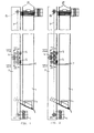
- the storage device shown in Figures 1 to 3 only includes a memory, which in turn consists of an interchangeable magazine 1 and a magazine carrier 2 and the associated facilities for storage and the transport of the card-shaped data carriers stored in the magazine 1 D and for the separation and removal of the individual Disk D exists.
- magazine 1 there are data carriers of the same thickness stored, for example EC cards, chip cards, transponder cards and Magnetic cards.
- card-shaped data carriers D of different types and Thickness must be saved for each card type and card thickness Magazine 1 can be arranged.
- the structure and mode of operation of these existing storage from magazine 1 and magazine carrier 2 is identical, so that based on that shown in Figures 1 to 3 Embodiment only such a memory is described.
- the magazine 1 shows a C-shaped cross section, as can be seen from FIGS. 8 and 9.
- the front 1a forming the web of this C-shaped cross section itself forming a right angle from the parallel to each other extending legs of the C-shaped cross section formed side walls 1b of magazine 1, which at the end turned at a right angle are and form opposing legs 1c.
- the side walls 1b according to FIG. 10 form cover strips 1d bent.
- the magazine 1 is provided with an output slot 1e.
- the lower end of the magazine 1 is chamfered.
- the magazine 1 which at Exemplary embodiment by two strip-shaped supports on the side walls 1b is formed, which has a through opening for the Form tray 3.
- the card-shaped data carriers D lie on when a filled magazine 1 is attached to the magazine carrier 2.
- the magazine carrier 2 which is in the embodiment is formed with a U-shaped cross section, in its lower Provide area with two inclined support arms 2a, one have an angular cross-section, the vertical leg of the lateral Management of the magazine 1 and its horizontal leg to support the Magazine 1 serves.
- a filled magazine 1 is from bottom to top of the Magazine carrier 2 attached, guided between the support arms 2a and then locked by a tab 2b arranged on the magazine carrier 2, with a locking bolt engaging in a locking opening of the magazine 1 2c is provided.
- a vertically movable support base 3 is on the magazine support 2 movably guided, an embodiment of which is best shown in the figures 8 and 9 can be seen.
- This support floor 3 is on a slide 4 arranged, which consists of two mutually parallel slide walls 4a and 4b. While the front carriage wall 4a integrally with the Support base 3 is formed by an angle plate, it is in the rear slide wall 4b around a separate sheet metal part, which according to FIG by means of two bolts 4c with the front slide wall 4a connected is.
- the support base 3 shown in a top view in FIG. 9 is forked with two bottom halves 3a running at a distance from one another.
- each Bottom half 3a is provided with a lateral recess 3b, in each a leg 1c of the magazine 1 protrudes, as can be seen in FIG. This ensures that the magazine 1 is not from Magazine carrier 2 can be removed as long as the base 3 in his work area.
- the carriage 4 is driven by a at the lower end of the Magazine carrier 2 arranged motor 6 via a flexible tension element, the is designed as a toothed belt 7 in the embodiment, but also as V-belt or chain can be executed.
- This toothed belt 7 is over two arranged outside the range of motion 4 of the magazine carrier 2 Deflection rollers 8a and 8b, of which the lower deflection roller 8a on the Drive shaft of the motor 6 sits and thus from this motor 6, namely in is drivable in both directions.
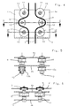
- each drive roller 9 is two laterally offset guide rollers 10 assigned, which are freely rotatable on a Axis 11 are mounted, on which the rollers 5 are freely rotatable ( Figure 6).
- the drive rollers 9 are non-rotatable Arranged on a shaft 12, which to the rear from the rear sled wall 4b of the carriage 4 protrudes, each on this protruding end Shaft 12 each have a differential roller 13a or 13b rotatably attached.
- the differential rollers 13a and 13b have a different one Diameter or a different number of teeth.
- the drive rollers 9 with 21 teeth
- the differential roller 13a also with Provide 21 teeth
- the differential roller 13b with 18 teeth.
- the Differential rollers 13a and 13b are endlessly flexible with each other Connection element connected, which in turn in the embodiment as endless toothed belt 14 is executed (Fig. 7). The better clarity because of Figures 4 to 6 and 8, both the toothed belt 7 and the toothed belt 14 has been omitted. 2, the toothed belt 7 only indicated by dash-dotted lines; the timing belt 14 was again omitted.
- the drive rollers 9 of the Slide 4 with the same direction of rotation and with the same angular velocity driven.
- these drive rollers 9 are non-rotatable via the shafts 12 are connected to the differential rollers 13a and 13b, respectively have different number of teeth, depending on the direction of rotation of the Timing belt 7 a relative movement of the carriage 4 in the longitudinal direction of the Magazine carrier 2, since that of the differential rollers 13a and 13b different angles of rotation imposed by a relative movement of the carriage 4 compared to the rotating toothed belt 7 Need to become.
- the differential gear formed in this way is for the circumferential toothed belt 7 self-locking and enables the rulers Processing large forces.
- the ratio of the number of teeth of the differential rollers 13a and 13b gives the path for the movement of the carriage 4 relative to the Magazine carrier 2 and thus for the movement of the carriage 4 arranged tray 3.
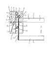
- a selection motor 15 is provided, the drive roller as Separating roller 15a is formed on the top of each top card-shaped data carrier D acts in magazine 1.
- the Motor housing of the selection motor 15 is parallel, however Eccentric pivot axis 15b pivotable mounted on the magazine carrier 2 and provided with a switching arm 15c, which with a switch 16 cooperates.
- the pair of rollers consisting of transport roller 17 and retaining roller 18 in the exemplary embodiment, a pair of puller rollers arranged from a driven by the intermediate gear 20 in the same direction with the transport roller 17 Roller 21 and a freely rotatable, against the driven roller 21st there is a counter roller 22 pressed by spring force.
- the transport roller 17 can of the transport motor 19 in both directions of rotation are driven not only from the output slot 1e of the associated magazine 1 coming data carrier D for further processing or the output, but also from an upstream To transport magazine coming data carriers.
- the gap formed by these rollers 17 and 23 is one Assigned guide plate 24 on which the magazine 1 above the Separation roller 15a passing data carrier D lie on.
- the roller 21 driven in the same direction with the transport roller 17 is at Embodiment assigned a pressure roller 25. To use this enable, has the retaining roller 18 when driving the transport roller in Clockwise a freewheel.
- the storage device comprises a plurality of memories, as shown in FIG. 11 is shown based on two memories, are each adjacent memories to each other in height by the distance between that through the Transport roller 17 and the retaining roller 18 formed by the gap the transport roller 18 and the pressure roller 23 formed gap.
- the magazine 1 of the left-hand memory deducted card-shaped data carrier D the leave the transport device formed by the transport motor 19, reliably on the top of the guide plate 24 of the right memory arrive and here between the transport roller 17 and the pressure roller 23 formed gap are fed.
- the transport device of the left memory card-shaped data carrier D are delivered, the if they already come from a further arranged storage, they occur from the gap formed between the roller 21 and the pressure roller 25.
- a baffle 26 is provided, one funnel-shaped supply of this data carrier D to the associated gap causes.
- Figures 10 and 11 finally show that in front of the magazine carrier 2 Support housing 27 is arranged on which the selection motor 15, the Transport motor 19 and all associated roles are arranged. It This also results in a structurally simple design for this assembly Unit.
Landscapes
- Physics & Mathematics (AREA)
- General Physics & Mathematics (AREA)
- Conveying Record Carriers (AREA)
- Credit Cards Or The Like (AREA)
- Sheets, Magazines, And Separation Thereof (AREA)
Abstract
Description
Die Erfindung betrifft eine Speichervorrichtung für kartenförmige Datenträger mit mindestens einem Speicher, in dem die kartenförmigen Datenträger auf einem höhenbeweglichen Tragboden aufeinanderliegend angeordnet sind und aus dem der jeweils oberste Datenträger durch eine Vereinzelungsrolle seitlich durch einen Ausgabeschlitz abziehbar und einer Antriebsrolle zur Weitergabe an eine nachgeschaltete Verarbeitung und/oder zur Ausgabe zuführbar ist.The invention relates to a storage device for card-shaped data carriers with at least one memory in which the card-shaped data carrier a vertically movable support base are arranged one on top of the other and from which the top data carrier by a separating roller laterally removable through an output slot and a drive roller for transfer can be fed to downstream processing and / or output.
Derartige Speichervorrichtungen für kartenförmige Datenträger sind in verschiedenen Ausführungsformen, beispielsweise zur Ausgabe von Benutzerberechtigungskarten für Parkhäuser bekannt. In der älteren europäischen Patentanmeldung 96 110 551.7 ist eine selbstauffüllende Speichervorrichtung für kartenförmige Datenträger beschrieben, die aus mehreren Speichern besteht und eine selbsttätige Auffüllung und/oder Entleerung aller Speicher ermöglicht. Eine Vorrichtung dieser Art ist in DE 19 605 106 auch offenbart.Such storage devices for card-shaped data carriers are in different Embodiments, for example for issuing user authorization cards known for parking garages. In the older European Patent application 96 110 551.7 is a self-replenishing storage device described for card-shaped data carriers that consist of several memories exists and an automatic filling and / or emptying of all storage allows. A device of this type is also disclosed in DE 19 605 106.
Der Erfindung liegt die Aufgabe zugrunde, eine Speichervorrichtung der als bekannt vorausgesetzten Art mit mindestens einem Speicher zu schaffen, die konstruktiv einfach und damit preisgünstig herstellbar ist und einen Grundaufbau besitzt, der in verschiedenen Ausbaustufen ausbaubar ist und eine hohe Funktionssicherheit besitzt, so daß die Speichervorrichtung an unterschiedliche Anforderungen angepaßt werden kann.The invention has for its object a storage device to provide as known known type with at least one memory, which is structurally simple and therefore inexpensive to manufacture and has a basic structure owns, which can be expanded in different expansion stages and one has high reliability, so that the storage device to different Requirements can be adjusted.
Die Lösung dieser Aufgabenstellung durch die Erfindung ist dadurch gekennzeichnet, daß der Tragboden an einem Schlitten angeordnet ist, der höhenbeweglich an einem Magazinträger geführt und von einem Motor durch ein endloses biegsames Zugelement antreibbar ist, das über zwei außerhalb des Bewegungsbereiches des Schlittens am Magazinträger angeordnete Umlenkrollen geführt ist und zwei am Schlitten frei drehbar gelagerte Antriebsrollen gleichen Durchmessers in gleichem Drehsinn antreibt, die miteinander durch ein Differenzgetriebe verbunden sind.The solution to this problem by the invention is thereby characterized in that the support base is arranged on a carriage which vertically movable on a magazine carrier and by a motor an endless flexible traction element can be driven, which has two outside of the range of movement of the slide arranged on the magazine carrier Deflection rollers is guided and two freely rotatably mounted on the carriage Drive rollers of the same diameter in the same direction that drives are interconnected by a differential gear.
Das endlose, über die Umlenkrollen geführte biegsame Zugelement, beispielsweise ein Zahnriemen oder eine Kette, wird durch den Motor in einer von zwei möglichen Drehrichtungen angetrieben und treibt hierbei seinerseits mit jedem Trum eine der beiden Antriebsrollen an, die frei drehbar am Schlitten gelagert sind. Da diese Antriebsrollen denselben Durchmesser haben und in gleichem Drehsinn angetrieben werden, ergäbe sich keine Bewegung des Schlittens. Diese wird erst dadurch erzielt, daß die beiden Antriebsrollen durch ein Differenzgetriebe miteinander verbunden sind. Dieses Differenzgetriebe bewirkt, daß der Verdrehwinkel der beiden Antriebsrollen trotz ihrer gleichen Durchmesser unterschiedlich ist. Da die beiden Trums des biegsamen Zugelements sich zwangsweise mit gleicher Geschwindigkeit bewegen, wird hierdurch eine Relativbewegung des Schlittens zum biegsamen Zugelement und damit zum Magazinträger erzwungen. Die Richtung und Größe dieser Relativbewegung ist von der Drehrichtung des Motors und der Differenz der Verdrehwinkel der Antriebsrollen abhängig, so daß sie durch die Ausbildung des jeweiligen Differenzgetriebes bestimmt werden kann.The endless flexible traction element guided over the deflection rollers, for example A timing belt, or chain, is driven by the engine in one of two possible directions of rotation driven and in turn drives with each Run on one of the two drive rollers, which are freely rotatable on the slide are. Since these drive rollers have the same diameter and the same If the direction of rotation were driven, there would be no movement of the slide. This is achieved only in that the two drive rollers by a Differential gears are interconnected. This differential gear causes the twist angle of the two drive rollers despite their being the same Diameter is different. Because the two strands of the flexible tension element is forced to move at the same speed this results in a relative movement of the slide to the flexible tension element and thus forced to the magazine carrier. The direction and size of this Relative movement is based on the direction of rotation of the motor and the difference in Angle of rotation of the drive rollers dependent, so that they by training of the respective differential gear can be determined.
Gemäß einem weiteren Merkmal der Erfindung wird das Differenzgetriebe durch zwei durch ein endloses biegsames Verbindungselement miteinander verbundene Differenzrollen gebildet, die gemeinsam mit jeweils einer Antriebsrolle verdrehfest auf einer Verbindungswelle angeordnet und mit unterschiedlichem Durchmesser ausgebildet sind. Durch die unterschiedlichen Durchmesser der Differenzrollen und ihre Verbindung mittels eines endlosen biegsamen Zugelements, insbesondere eines Zahnriemens oder einer Kette, wird den Antriebsrollen ein unterschiedlicher Verdrehwinkel aufgezwungen, der dazu führt, daß der die Antriebsrollen lagernde Schlitten eine Ausgleichsbewegung in Längsrichtung des umlaufenden biegsamen Zugelements, d.h. in Längsrichtung des Magazinträgers ausführt, auf dem die Umlenkrollen für das biegsame Zugelement gelagert sind. Diese Ausgleichsbewegung hängt vom Unterschied der Durchmesser der Differenzrollen ab und ergibt einen selbsthemmenden Antrieb für den Tragboden, der die lineare Verarbeitung großer Kräfte und eine sehr präzise Bewegung des Tragbodens über dessen gesamten Bewegungsbereich ermöglicht, wie dies für die gesteuerte Zufuhr der einzelnen kartenförmigen Datenträger zum Ausgabeschlitz des Magazins erforderlich ist.According to a further feature of the invention, the differential gear by two through an endless flexible connecting element connected differential roles formed, each with a drive role non-rotatably arranged on a connecting shaft and with different Diameter are formed. Due to the different diameters the differential rollers and their connection by means of an endless flexible Traction element, in particular a toothed belt or a chain, is a different angle of rotation is imposed on the drive rollers causes the carriage supporting the drive rollers to perform a compensatory movement in the longitudinal direction of the circumferential flexible tension element, i.e. in Longitudinal direction of the magazine carrier on which the guide rollers for the flexible tension element are stored. This compensatory movement depends on Difference in the diameter of the differential rollers and results in a self-locking Drive for the supporting floor, which is the linear processing large Forces and a very precise movement of the tray over its entire length Movement range allows, as is the case for the controlled feeding of the individual card-shaped data carriers are required for the magazine output slot is.
Bei einer bevorzugten Ausführungsform der Erfindung sind das biegsame Zugelement und das biegsame Verbindungselement als Zahnriemen und die Antriebsrollen sowie Differenzrollen als gezahnte Riemenrollen ausgebildet. Hierdurch wird mit geringem technischen Aufwand ein Schlupf zwischen dieses Antriebsteilen ausgeschlossen.In a preferred embodiment of the invention, these are flexible Tension element and the flexible connecting element as a toothed belt and the Drive rollers and differential rollers are designed as toothed belt rollers. As a result, there is a slip between with little technical effort this drive parts excluded.
Um einen ausreichend großen Umschlingungswinkel des biegsamen. Zugelements bezüglich der Antriebsrollen und damit eine schlupffreie Kraftübertragung sicherzustellen, ist gemäß einem weiteren Merkmal der Erfindung das biegsame Zugelement zu beiden Seiten jeder Antriebsrolle über seitlich versetzt angeordnete Führungsrollen geführt.To a sufficiently large wrap angle of the flexible. pulling element regarding the drive rollers and thus a slip-free Ensuring power transmission is according to another characteristic of Invention of the flexible traction element on both sides of each drive roller laterally offset guide rollers.
Weiterhin wird mit der Erfindung vorgeschlagen, den Schlitten mittels Laufrollen in Längsrichtung des Magazinträgers zu führen, so daß eine vereckungsfreie Bewegung des Schlittens erreicht wird.Furthermore, the invention proposes the carriage by means of rollers to run in the longitudinal direction of the magazine carrier, so that a cover-free Movement of the carriage is achieved.
Gemäß einem weiteren Merkmal der Erfindung besteht der Speicher aus dem Magazinträger und einem auswechselbaren Magazin, das zur Aufnahme der kartenförmigen Datenträger mit einem festen Magazinboden versehen und mittels zweier Tragarme am Magazinträger festlegbar ist. Hierdurch ergibt sich ein konstruktiv einfacher Aufbau und eine einfache Auswechslung jedes Speichers.According to a further feature of the invention, the memory consists of the Magazine carrier and an interchangeable magazine that holds the card-shaped data carriers with a fixed magazine bottom and can be fixed on the magazine carrier by means of two support arms. This results in a structurally simple structure and a simple replacement of each Memory.
Mit der Erfindung wird weiterhin vorgeschlagen, den Magazinboden mit mindestens einer Durchtrittsöffnung für den Tragboden zu versehen. Diese Ausbildung ermöglicht es, ein gefülltes Magazin, in dem die kartenförmigen Datenträger auf dem Magazinboden liegen, an den Magazinträger anzusetzen, wobei sich der Tragboden in seiner tiefsten Stellung befindet, die unterhalb des an den Magazinträger angesetzten Magazinbodens liegt. Durch anschließendes Hochfahren des Tragbodens tritt dieser durch die Durchtrittsöffnung im Magazinboden und übernimmt die kartenförmigen Datenträger, die somit vom Magazinboden abgehoben und nacheinander je nach Bedarf dem Ausgabeschlitz zu geführt werden.The invention also proposes using the magazine base to provide at least one passage opening for the supporting floor. This Training enables a filled magazine in which the card-shaped Data carriers lie on the magazine base, to be attached to the magazine carrier, the supporting floor is in its lowest position, the one below of the magazine base attached to the magazine carrier. By subsequent Raising the support floor passes through the passage opening in the magazine bottom and takes over the card-shaped data carriers that thus lifted off the magazine bottom and one after the other as required Output slot to be performed.
Um ein Abnehmen des auswechselbaren Magazins vom Magazinträger während des Betriebes der Speichervorrichtung zu verhindern, ist das Magazin gemäß einem weiteren Merkmal der Erfindung mit in seitliche Aussparungen des Tragbodens hineinragenden Wandteilen ausgebildet. Diese Wandteile verhindern ein Abnehmen des Magazins vom Magazinträger, wenn sich der Tragboden im Bereich des Magazins, d.h. in seinem Arbeitsbereich befindet.To remove the interchangeable magazine from the magazine carrier The magazine is to prevent during the operation of the storage device according to a further feature of the invention with in side recesses protruding wall parts. These wall parts prevent the magazine from being removed from the magazine carrier if the Tragboden in the area of the magazine, i.e. is in his work area.
Bei einer bevorzugten Ausführungsform der Erfindung ist das Magazin mit einem C-förmigen Querschnitt ausgebildet, dessen gegeneinanderweisende Schenkel in jeweils eine von zwei einander gegenüberliegende Aussparungen am Tragboden hineinragen. Hierdurch ergibt sich eine besonders einfache Gestaltung des Magazins, das nur in der tiefsten Endstellung des Tragbodens vom Magazinträger abnehmbar ist.In a preferred embodiment of the invention, the magazine is included a C-shaped cross-section, its opposing Each leg in one of two opposite recesses protrude from the supporting floor. This results in a particularly simple design of the magazine, which is only in the lowest end position of the tray is removable from the magazine carrier.
Gemäß einem weiteren Merkmal der Erfindung ist das Magazin an seiner Unterseite abgeschrägt und auf entsprechend schräg nach unten verlaufende Tragarme aufgesetzt, die am Magazinträger befestigt sind. Durch diese schräge Ausbildung des Magazins an seiner Unterseite kann dieses trotz der in die Aussparungen des Tragbodens hineinragenden Schenkel vom Magazinträger abgenommen werden, wenn sich der Tragboden in diesem schrägen Bereich des Magazins befindet, da die gegeneinanderweisenden Schenkel vor diesem schrägen Bereich des Magazins enden.According to a further feature of the invention, the magazine is on it Sloping underside and correspondingly sloping downwards Support arms attached, which are attached to the magazine carrier. Through this oblique formation of the magazine on its underside can this despite the in the recesses of the supporting leg protruding from Magazine carriers can be removed when the tray is in this oblique area of the magazine because the opposing Legs end in front of this slanted area of the magazine.
Mit der Erfindung wird weiterhin vorgeschlagen, das Magazin mittels einer am Magazinträger angeordneten Lasche festzulegen, die mit einem in eine Riegelöffnung eingreifenden Riegelbolzen versehen ist. With the invention it is further proposed that the magazine by means of a Magazine carrier arranged tab set with a in a bolt opening engaging locking bolt is provided.
Um die im Magazin befindlichen kartenförmigen Datenträger jeweils von oben aus dem seitlichen Ausgabeschlitz einzeln abzuziehen, ist die auf die Oberseite des jeweils obersten kartenförmigen Datenträgers einwirkende Vereinzelungsrolle als Abtriebsrolle eines Selektionsmotors ausgebildet, dessen Motorgehäuse um eine parallele, jedoch exzentrisch zur Motorachse verlaufende Schwenkachse verschwenkbar am Magazinträger gelagert ist. Mit diesem erfindungsgemäßen Vorschlag ergibt sich eine besonders einfache Vereinzelungsvorrichtung, die gezielt ansteuerbar ist.Around the card-shaped data carriers in the magazine from above to be removed individually from the side delivery slot is on the top of the uppermost card-shaped data carrier formed as an output roller of a selection engine, the Motor housing around a parallel, but eccentric to the motor axis Swivel axis is pivotally mounted on the magazine carrier. With This proposal according to the invention results in a particularly simple separating device, which can be specifically controlled.
Das Motorgehäuse des Selektionsmotors ist erfindungsgemäß über seine als Vereinzelungsrolle dienende Abtriebsrolle und über den jeweils obersten kartenförmigen Datenträger durch den Tragboden in seine Wirkstellung verschwenkbar, so daß immer dann ein kartenförmiger Datenträger aus dem seitlichen Ausgabeschlitz des Magazins ausgegeben werden kann, wenn der jeweils oberste kartenförmige Datenträger in seine Ausgabeposition vor dem Ausgabeschlitz durch den Tragboden überführt wird.The motor housing of the selection motor is according to the invention via its as Separating output pulley and above the top one card-shaped data carrier can be pivoted into its operative position through the supporting base, so that then always a card-shaped data carrier from the side Output slot of the magazine can be output if the respective top card-shaped data carrier in its output position in front of the Output slot is transferred through the tray.
Sofern die Wirkstellung der Vereinzelungsrolle gemäß einem weiteren Merkmal der Erfindung durch einen Schalter überwacht wird, der durch die- Verschwenkbewegung der Motorgehäuse betätigt ist, ist eine gezielte Ausgabe des jeweils obersten kartenförmigen Datenträgers möglich, sobald dieser durch eine Bewegung des Tragbodens in seine Ausgabeposition gebracht worden ist.If the operative position of the separation role according to another feature the invention is monitored by a switch that by the pivoting movement the motor housing is actuated, is a targeted output of the top card-shaped data carrier possible as soon as this brought into its dispensing position by moving the support base has been.
Um auch den Abtransport des seitlich aus dem Ausgabeschlitz des Magazins ausgegebenen Datenträgers zwecks Weitergabe an eine nachgestaltete Verarbeitung und/oder zwecks Ausgabe an einen Benutzer zu vereinfachen, ist die Transportrolle gemäß einem weiteren Merkmal der Erfindung seitlich oberhalb des Ausgabeschlitztes des Magazins angeordnet und durch einen Transportmotor antreibbar, der über ein Zwischenzahnrad zugleich eine unterhalb der Transportrolle angeordnete Rückhalterolle in derselben Drehrichtung wie die Transportrolle antreibt, wobei zwischen dieser Rückhalterolle und der Transportrolle ein Spalt gebildet ist, der größer als die Dicke und kleiner als die zweifache Dicke der kartenförmigen Datenträger ist. To also remove the magazine from the side of the output slot issued data medium for the purpose of forwarding to a reworked processing and / or to simplify it for output to a user the transport roller according to a further feature of the invention laterally above the output slot of the magazine and arranged by a Transport motor drivable, the one via an intermediate gear Retaining roller arranged below the transport roller in the same direction of rotation how the feed roller drives, being between this retention roller and the transport roller is formed a gap which is larger than the thickness and is less than twice the thickness of the card-shaped data carrier.
Diese erfindungsgemäße Ausbildung der der Vereinzelungsvorrichtung nachgeschalteten Transportvorrichtung stellt einerseits sicher, daß lediglich der oberste kartenförmige Datenträger aus dem Magazin abgezogen wird, da ein insbesondere durch Reibung zwischen den Datenträgern mitgenommener weiterer Datenträger durch die in entgegengesetzter Transportrichtung zur Transportrolle angetriebene Rückhalterolle in das Magazin zurückgeführt wird.This inventive design of the separation device downstream Transport device ensures on the one hand that only the top card-shaped data carrier is pulled out of the magazine as a especially entrained by friction between the data carriers additional data carriers through the in the opposite transport direction Transport roller driven retention roller is returned to the magazine.
Andererseits ermöglicht diese Grundkonzeption der Transportvorrichtung, daß gemäß einem weiteren Merkmal der Erfindung dem aus Transport- und Rückhalterolle bestehenden Rollenpaar ein Abzugsrollenpaar nachgeordnet wird, das aus einer vom Zwischenzahnrad gleichsinnig mit der Transportrolle angetriebenen Rolle und einer frei drehbar gelagerten, gegen die angetriebene Rolle durch Federkraft angedrückten Gegenrolle besteht. Der der Weiterverarbeitung zuzuführende bzw. auszugebende kartenförmige Datenträger wird somit von zwei Rollenpaaren erfaßt, wodurch sich eine sehr hohe Funktionssicherheit ergibt.On the other hand, this basic design of the transport device enables that according to a further feature of the invention that of transport and retention role a puller roller pair is subordinated to an existing roller pair, the one from the idler gear in the same direction as the transport roller driven roller and a freely rotatable, against the driven There is a counter roller pressed by spring force. The the Card-shaped to be fed or issued for further processing Data carrier is thus captured by two pairs of roles, which is a very high functional reliability results.
Wenn gemäß einem weiteren Merkmal der Erfindung die Transportrolle in beiden Drehrichtungen antreibbar ist und mit einer oberhalb angeordneten Andrückrolle zusammenwirkt, können dem durch diese Rollen gebildeten Spalt kartenförmige Datenträger aus einem benachbarten Speicher zur Weitergabe zugeführt werden, wobei dem durch diese Rollen gebildeten Spalt ein Führungsblech für aus einem benachbarten Speicher kommende kartenförmige Datenträger zugeordnet ist.If, according to a further feature of the invention, the transport roller in two directions of rotation can be driven and with one arranged above Pressure roller cooperates, the gap formed by these rollers card-shaped data carrier from a neighboring memory for distribution are supplied, the gap formed by these rollers Guide plate for card-shaped coming from a neighboring store Disk is assigned.
Um benachbarte Speicher dicht nebeneinander anordnen zu können, wird mit der Erfindung weiterhin vorgeschlagen, jeweils benachbarte Speicher zueinander in der Höhe um den Abstand zwischen dem durch die Transportrolle und die Rückhalterolle gebildeten Spalt und dem durch die Transportrolle und die Andrückrolle gebildeten Spalt zu versetzen. Hierdurch ergibt sich ein im wesentlichen gradliniger Verlauf für den Transport der aus den hinteren Speichern kommenden Datenträger.To be able to arrange adjacent storage tanks close to each other, use the invention further proposed each adjacent memory to each other in height by the distance between that through the Transport roller and the retaining roller and the gap formed by the Transport roller and the pressure roller formed gap. hereby there is an essentially straight course for the transport of the disk coming in the rear storage.
Damit in unterschiedlicher Höhe ankommende Datenträger, nämlich die aus dem unmittelbar benachbarten Speicher und die aus einem weiter entfernt liegenden Speicher ankommenden Datenträger sicher dem durch die Transportrolle und die oberhalb angeordnete Andrückrolle gebildeten Spalt zugeführt werden, wird gemäß einem weiteren Merkmal der Erfindung oberhalb des Führungsbleches ein Leitblech angeordnet, das kartenförmige Datenträger der benachbarten Speicher dem durch die Transportrolle und die Andrückrolle gebildeten Spalt zuführt.This means that data carriers arriving at different heights, namely those from the immediately adjacent store and the one further away the incoming storage media safely through the Transport roller and the gap formed above the pressure roller are supplied according to a further feature of the invention A guide plate is arranged above the guide plate, the card-shaped one Data carrier of the neighboring storage through the transport roller and Pressure roller feeds formed gap.
Mit der Erfindung wird schließlich vorgeschlagen, den Selektionsmotor, den Transportmotor und sämtliche zugehörigen Rollen an einem Traggehäuse anzuordnen, das oberhalb des auswechselbaren Magazins und vor dem zugehörigen Magazinträger am Magazinträger angeordnet ist. Hierdurch ergibt sich eine besonders einfache Konstruktion für die erfindungsgemäße Speichervorrichtung.Finally, the invention proposes the selection engine, the To arrange the transport motor and all associated rollers on a support housing, that above the interchangeable magazine and in front of the associated one Magazine carrier is arranged on the magazine carrier. This gives a particularly simple construction for the storage device according to the invention.
Auf der Zeichnung ist ein Ausführungsbeispiel der erfindungsgemäßen Speichervorrichtung dargestellt, und zwar zeigen:
- Fig. 1
- eine Seitenansicht eines Speichers,
- Fig. 2
- einen senkrechten Längsschnitt durch den Speicher gemäß der Abbildung Fig.1,
- Fig. 3
- eine rückwärtige Ansicht des Speichers gemäß der Fig. 1 und 2,
- Fig. 4
- eine vergrößerte Darstellung des Schlittens gemäß der Schnittlinie IV - IV in Fig. 2,
- Fig. 5
- einen Querschnitt durch den Schlitten gemäß der Schnittlinie V - V in Fig. 4,
- Fig. 6
- einen weiteren Querschnitt durch den Schlitten gemäß der Schnittlinie VI - VI in Fig. 4,
- Fig. 7
- eine vergrößerte Darstellung des Schlittens gemäß der Schnittlinie VII - VII in Fig. 2,
- Fig. 8
- eine Seitenansicht des in der unteren Endstellung befindlichen Schlittens und des unteren Endes des Magazins,
- Fig. 9
- einen waagerechten Schnitt durch das Magazin gemäß der Schnittlinie IX - IX in Fig. 8 und eine Draufsicht auf den Trag- und Magazinboden,
- Fig. 10
- eine schematische Frontansicht des oberen Endes eines Magazins sowie der Vereinzelungs- und Transportvorrichtung und
- Fig. 11
- eine der Fig. 10 entsprechende Frontansicht zweier nebeneinanderliegender Speicher.
- Fig. 1
- a side view of a memory,
- Fig. 2
- a vertical longitudinal section through the memory according to Figure Fig.1,
- Fig. 3
- 2 shows a rear view of the memory according to FIGS. 1 and 2,
- Fig. 4
- 3 shows an enlarged illustration of the slide according to the section line IV-IV in FIG. 2,
- Fig. 5
- 3 shows a cross section through the carriage along the section line V - V in FIG. 4,
- Fig. 6
- 4 shows a further cross section through the carriage according to the section line VI - VI in FIG. 4,
- Fig. 7
- 3 shows an enlarged illustration of the slide according to the section line VII-VII in FIG. 2,
- Fig. 8
- a side view of the carriage in the lower end position and the lower end of the magazine,
- Fig. 9
- 8 shows a horizontal section through the magazine according to section line IX - IX in FIG. 8 and a top view of the support and magazine bottom,
- Fig. 10
- is a schematic front view of the upper end of a magazine and the separating and transport device and
- Fig. 11
- one of the Fig. 10 corresponding front view of two adjacent storage.
Die in den Figuren 1 bis 3 dargestellte Speichervorrichtung umfaßt lediglich
einen Speicher, der seinerseits aus einem auswechselbaren Magazin 1 und
einem Magazinträger 2 sowie den zugehörigen Einrichtungen für die Lagerung
und den Transport der im Magazin 1 gespeicherten kartenförmigen Datenträger
D sowie für die Vereinzelung und den Abtransport der einzelnen
Datenträger D besteht. Im Magazin 1 sind jeweils Datenträger gleicher Dicke
gespeichert, beispielsweise EC-Karten, Chipkarten, Transponder-Karten und
Magnetkarten. Sollen kartenförmige Datenträger D unterschiedlicher Art und
Dicke gespeichert werden, müssen für jede Kartenart und Kartendicke eigene
Magazine 1 angeordnet werden. Der Aufbau und die Wirkungsweise dieser
aus Magazin 1 und Magazinträger 2 bestehenden Speicher ist jedoch
identisch, so daß anhand des in den Figuren 1 bis 3 dargestellten
Ausführungsbeispiels nur ein derartiger Speicher beschrieben wird.The storage device shown in Figures 1 to 3 only includes
a memory, which in turn consists of an
Bei dem auf der Zeichnung dargestellten Ausführungsbeispiel hat das Magazin
1 einen C-förmigen Querschnitt, wie aus den Figuren 8 und 9 hervorgeht. An
die den Steg dieses C-förmigen Querschnittes bildende Frontseite 1a schließen
sich unter Bildung eines rechten Winkels die aus den parallel zueinander
verlaufenden Schenkeln des C-förmigen Querschnittes gebildeten Seitenwände
1b des Magazins 1 an, die am Ende unter einem rechten Winkel abgebogen
sind und gegeneinanderweisende Schenkel 1c bilden. Zur Bildung eines oberen
Abschlusses sind die Seitenwände 1b gemäß Fig. 10 zu Deckelstreifen 1d
umgebogen. Im Bereich des rechts in Fig. 10 zu erkennenden Deckelstreifens
1d ist das Magazin 1 mit einem Ausgabeschlitz 1e versehen.In the embodiment shown in the drawing, the
Das untere Ende des Magazins 1 ist abgeschrägt. Im Bereich dieses abgeschrägten
Teils ist im Magazin 1 ein Magazinboden 1f angeordnet, der beim
Ausführungsbeispiel durch zwei leistenförmige Auflagen an den Seitenwänden
1b gebildet wird, die zwischen sich eine Durchgangsöffnung für den
Tragboden 3 bilden. Auf diesem fest im Magazin 1 angeordneten
Magazinboden 1f liegen die kartenförmigen Datenträger D auf, wenn ein
gefülltes Magazin 1 an den Magazinträger 2 angesetzt wird.The lower end of the
Zur Halterung des Magazins 1 ist der Magazinträger 2, der beim Ausführungsbeispiel
mit einem U-förmigen Querschnitt ausgebildet ist, in seinem unteren
Bereich mit zwei schräg verlaufenden Tragarmen 2a versehen, die einen
winkelförmigen Querschnitt haben, dessen senkrechter Schenkel zur seitlichen
Führung des Magazins 1 und dessen waagerechter Schenkel zur Auflage des
Magazins 1 dient. Ein gefülltes Magazin 1 wird von unten nach oben an den
Magazinträger 2 angesetzt, zwischen die Tragarme 2a geführt und anschließend
durch eine am Magazinträger 2 angeordnete Lasche 2b verriegelt,
die mit einem in eine Riegelöffnung des Magazins 1 eingreifenden Riegelbolzen
2c versehen ist.To hold the
Um die im auswechselbaren Magazin 1 gespeicherten kartenförmigen
Datenträger D einzeln aus dem Ausgabeschlitz 1 jedes Magazins 1
abzuziehen, ist am Magazinträger 2 ein höhenbeweglicher Tragboden 3
beweglich geführt, von dem ein Ausführungsbeispiel am besten in den Figuren
8 und 9 zu erkennen ist. Dieser Tragboden 3 ist an einem Schlitten 4
angeordnet, der aus zwei parallel zueinander verlaufenden Schlittenwänden 4a
und 4b besteht. Während die vordere Schlittenwand 4a einstückig mit dem
Tragboden 3 durch ein Winkelblech gebildet wird, handelt es sich bei der
hinteren Schlittenwand 4b um ein separates Blechteil, das gemäß Figur 7
mittels zweier Schraubenbolzen 4c mit der vorderen Schlittenwand 4a
verbunden ist. To the card-shaped stored in the
Der in Figur 9 in einer Draufsicht gezeichnete Tragboden 3 ist gabelförmig mit
zwei im Abstand zueinander verlaufenden Bodenhälften 3a ausgebildet. Jede
Bodenhälfte 3a ist mit einer seitlichen Aussparung 3b versehen, in die jeweils
ein Schenkel 1c des Magazins 1 hineinragt, wie in Figur 9 zu erkennen ist.
Hierdurch wird sichergestellt, daß das Magazin 1 solange nicht vom
Magazinträger 2 abgenommen werden kann, solange sich der Tragboden 3 in
seinem Arbeitsbereich befindet.The
Vor der vorderen Schlittenwand 4a des Schlittens 4 sind insgesamt vier
Laufrollen 5 frei drehbar angeordnet, die paarweise in Führungsnuten 2d des
Magazinträgers 2 eingreifen, so daß der Schlitten 4 in der Höhe längs des
Magazinträgers 2 bewegt werden kann.In front of the
Der Antrieb des Schlittens 4 erfolgt durch einen am unteren Ende des
Magazinträgers 2 angeordneten Motor 6 über ein biegsames Zugelement, das
beim Ausführungsbeispiel als Zahnriemen 7 ausgeführt ist, aber auch als
Keilriemen oder Kette ausgeführt sein kann. Dieser Zahnriemen 7 ist über zwei
außerhalb des Bewegungsbereiches 4 des Magazinträgers 2 angeordnete
Umlenkrollen 8a und 8b geführt, von denen die untere Umlenkrolle 8a auf der
Antriebswelle des Motors 6 sitzt und somit von diesem Motor 6, und zwar in
beiden Richtungen antreibbar ist.The
Wie aus den Figuren 4 bis 8 hervorgeht, sind zwischen den beiden
Schlittenwänden 4a und 4b des Schlittens 4 zwei Antriebsrollen 9 drehbar
gelagert, die jeweils mit einem Trum des Zahnriemens 7 zusammenwirken. Um
einen ausreichend großen Umschlingungswinkel für den Zahnriemen 7 um die
jeweilige Antriebsrolle 9 zu erzielen, sind gemäß 4 jeder Antriebsrolle 9 zwei
seitlich versetzte Führungsrollen 10 zugeordnet, die frei drehbar auf einer
Achse 11 gelagert sind, auf der auch die Laufrollen 5 frei drehbar sind (Figur
6).As can be seen from FIGS. 4 to 8, there are between the two
Wie insbesondere aus Figur 5 hervorgeht, sind die Antriebsrollen 9 drehfest
auf einer Welle 12 angeordnet, die nach hinten aus der hinteren Schlittenwand
4b des Schlittens 4 herausragt, wobei auf diesem herausragenden Ende jeder
Welle 12 jeweils eine Differenzrolle 13a bzw. 13b drehfest befestigt ist. As can be seen in particular from FIG. 5, the
Während die Antriebsrollen 9 denselben Durchmesser und dieselbe Zähnezahl
aufweisen, haben die Differenzrollen 13a und 13b einen unterschiedlichen
Durchmesser bzw. eine unterschiedliche Zähnezahl. Beim Ausführungsbeispiel
sind die Antriebsrollen 9 mit 21 Zähnen, die Differenzrolle 13a ebenfalls mit
21 Zähnen und die Differenzrolle 13b mit 18 Zähnen versehen. Die
Differenzrollen 13a und 13b sind miteinander durch ein endloses biegsames
Verbindungselement verbunden, das beim Ausführungsbeispiel wiederum als
endloser Zahnriemen 14 ausgeführt ist (Fig. 7). Der besseren Übersichtlichkeit
wegen sind in den Figuren 4 bis 6 und 8 sowohl der Zahnriemen 7 als auch
der Zahnriemen 14 weggelassen worden. In Fig. 2 wurde der Zahnriemen 7
lediglich strichpunktiert angedeutet; der Zahnriemen 14 wurde wiederum
weggelassen.While the
Wenn der Zahnriemen 7 durch die Umlenkrolle 8a vom Motor 6 in einer der
beiden Drehrichtungen angetrieben wird, werden die Antriebsrollen 9 des
Schlittens 4 mit gleichem Drehsinn und mit gleicher Winkelgeschwindigkeit
angetrieben. Da diese Antriebsrollen 9 jedoch über die Wellen 12 verdrehfest
mit den Differenzrollen 13a bzw. 13b verbunden sind, die eine
unterschiedliche Zähnezahl aufweisen, ergibt sich je nach Drehrichtung des
Zahnriemens 7 eine Relativbewegung des Schlittens 4 in Längsrichtung des
Magazinträgers 2, da die von den Differenzrollen 13a und 13b
aufgezwungenen unterschiedlichen Drehwinkel durch eine Relativbewegung
des Schlittens 4 gegenüber dem umlaufenden Zahnriemen 7 ausgeglichen
werden müssen. Das auf diese Weise gebildete Differenzgetriebe ist für den
umlaufenden Zahnriemen 7 selbsthemmend und ermöglicht die lineale
Verarbeitung großer Kräfte. Das Verhältnis der Zähnezahlen der Differnzrollen
13a und 13b ergibt den Weg für die Bewegung des Schlittens 4 relativ zum
Magazinträger 2 und damit für die Bewegung des am Schlitten 4
angeordneten Tragbodens 3. Durch Steuerung des Motors 6 ist es somit
möglich, in Magazin 1 befindliche kartenförmige Datenträger D gezielt dem
Ausgabeschlitz 1e zuzuführen.If the
Um den jeweils obersten kartenförmigen Datenträger D aus dem Magazin 1
abzuziehen, ist ein Selektionsmotor 15 vorgesehen, dessen Antriebsrolle als
Vereinzelungsrolle 15a ausgebildet ist, die auf die Oberseite des jeweils
obersten kartenförmigen Datenträgers D im Magazin 1 einwirkt. Das
Motorgehäuse des Selektionsmotors 15 ist um eine parallele, jedoch
exzentrisch zur Motorachse verlaufende Schwenkachse 15b verschwenkbar
am Magazinträger 2 gelagert und mit einem Schaltarm 15c versehen, der mit
einem Schalter 16 zusammenwirkt.Around the uppermost card-shaped data carrier D from
Durch das Gewicht des exzentrisch aufgehängten Selektionmotors 15 liegt die
Vereinzelungsrolle 15a mit der notwendigen Andrückkraft auf der Oberseite
des jeweils obersten kartenförmigen Datenträgers D im Magazin 1 -
gegebenenfalls verstärkt diese Federkraft - auf. Sobald dieser oberste
Datenträger D mit Hilfe des Tragbodens 3 derart weit im Magazin 1 nach oben
bewegt worden ist, daß der mit dem verschwenkenden Selektionsmotor 15
verbundene Schaltarm 15c den Schalter 16 betätigt, kann die Veinzelungsrolle
15a gemäß Fig. 10 im Gegenuhrzeigersinn angetrieben werden, um den
Datenträger D aus dem Ausgabeschlitz 1e des Magazins 1 herauszuführen.Due to the weight of the eccentrically suspended
Bei einer Austrittsbewegung des kartenförmigen Datenträgers D aus dem
Ausgabeschlitz 1e gelangt die vordere Kante des Datenträgers D zwischen ein
Rollenpaar, das durch eine Transportrolle 17 und eine Rückhalterolle 18
gebildet wird. Die Transportrolle 17 wird durch einen Transportmotor 19
angetrieben und treibt ihrerseits über ein Zwischenzahnrad 20 die
Rückhalterolle 18 in derselben Drehrichtung wie die Transportrolle 17 an.
Zwischen der Transportrolle 17 und der Rückhalterolle 18 ist ein Spalt
gebildet, der größer als die Dicke und kleiner als die zweifache Dicke der
kartenförmigen Datenträger D ist. Hierdurch wird bewirkt, daß die oberhalb
des Ausgabeschlitzes 1e angeordnete Transportrolle 17 den kartenförmigen
Datenträger D erfaßt und aus dem Magazin 1 vollständig abzieht, wogegen die
mit ihrer Oberseite in entgegengesetzter Richtung wie die Transportrolle 17
drehende Rückhalterolle 18 einen eventuell aufgrund von Reibung oder
Adhäsion zwischen den Datenträgern D mitgenommenen zweiten Datenträger
D in das Magazin 1 zurückbefördert. Der Spalt zwischen den Rollen 17 und 18
ist entsprechend den jeweils verwendenden Datenträgern D einstellbar.With an exit movement of the card-shaped data carrier D from the
Output slot 1e enters the front edge of the data carrier D between
Pair of rollers by a
Dem aus Transportrolle 17 und Rückhalterolle 18 bestehenden Rollenpaar ist
beim Ausführungsbeispiel ein Abzugsrollenpaar nachgeordnet, das aus einer
vom Zwischenzahnrad 20 gleichsinnig mit der Transportrolle 17 angetriebenen
Rolle 21 und einer frei drehbar gelagerten, gegen die angetriebene Rolle 21
durch Federkraft angedrückten Gegenrolle 22 besteht. Durch die Anordnung
zweier Rollenpaare wird die Sicherheit des Abtransportes der kartenförmigen
Datenträger D aus dem Magazin 1 erhöht.The pair of rollers consisting of
Die Transportrolle 17 kann vom Transportmotor 19 in beiden Drehrichtungen
angetrieben werden, um nicht nur aus dem Ausgabeschlitz 1e des
zugehörigen Magazins 1 kommende Datenträger D einer Weiterverarbeitung
bzw. der Ausgabe zuzuführen, sondern auch aus einem vorgeschalteten
Magazin kommende Datenträger zu transportieren. Zu diesem Zweck wirkt die
Transportrolle 17 mit einer oberhalb angeordneten Andrückrolle 23
zusammen. Dem durch diese Rollen 17 und 23 gebildeten Spalt ist ein
Führungsblech 24 zugeordnet, auf dem die das Magazin 1 oberhalb der
Vereinzelungsrolle 15a passierenden Datenträger D aufliegen. Auch der
gleichsinnig mit der Transportrolle 17 angetriebenen Rolle 21 ist beim
Ausführungsbeispiel eine Andrückrolle 25 zugeordnet. Um diesen Einsatz zu
ermöglichen, hat die Rückhalterolle 18 bei einem Antrieb der Transportrolle im
Uhrzeigersinn einen Freilauf.The
Sofern die Speichervorrichtung mehrere Speicher umfaßt, wie dies in Fig. 11
anhand zweier Speicher dargestellt ist, sind jeweils benachbarte Speicher
zueinander in der Höhe um den Abstand zwischen dem durch die
Transportrolle 17 und die Rückhalterolle 18 gebildeten Spalt und dem durch
die Transportrolle 18 und die Andrückrolle 23 gebildeten Spalt versetzt. Auf
diese Weise wird gemäß Fig. 11 sichergestellt, daß aus dem Magazin 1 des
links angeordneten Speichers abgezogene kartenförmige Datenträger D, die
die durch den Transportmotor 19 gebildete Transporteinrichtung verlassen,
zuverlässig auf die Oberseite des Führungsbleches 24 des rechten Speichers
gelangen und hier dem zwischen der Transportrolle 17 und der Andrückrolle
23 gebildeten Spalt zugeführt werden. Sofern aus der Transportvorrichtung
des linken Speichers kartenförmige Datenträger D abgegeben werden, die
bereits aus einem weiter vorher angeordneten Speicher stammen, treten diese
aus dem zwischen der Rolle 21 und der Andrückrolle 25 gebildeten Spalt aus.
Um auch diese kartenförmige Datenträger D zuverlässig dem durch die
Transportrolle 17 und die Andrückrolle 23 gebildeten Spalt des nachfolgenden
Speichers hinzuzuführen, ist schließlich ein Leitblech 26 vorgesehen, das eine
trichterförmige Zuführung dieser Datenträger D zum zugehörigen Spalt
bewirkt.If the storage device comprises a plurality of memories, as shown in FIG. 11
is shown based on two memories, are each adjacent memories
to each other in height by the distance between that through the
Die Figuren 10 und 11 zeigen schließlich, daß vor dem Magazinträger 2 ein
Traggehäuse 27 angeordnet ist, an dem der Selektionsmotor 15, der
Transportmotor 19 und sämtliche zugehörigen Rollen angeordnet sind. Es
ergibt sich somit auch für diese Baugruppe eine konstruktiv einfache
Baueinheit.Figures 10 and 11 finally show that in front of the
Nach dem Ansetzen eines mit kartenförmigen Datenträgern D gefüllten
Magazins 1 an den Magazinträger 2, das nur erfolgen kann, wenn sich der
Tragboden 3 unterhalb des Magazinbodens 1f befindet, wird der Tragboden 3
durch den Motor 6 mittels des Zahnriemens 7 und des zugehörigen
Differenzgetriebes angehoben, bis der Selektionsmotor 15 durch den obersten
kartenförmigen Datenträger D im Magazin 1 verschwenkt wird und den
Schalter 16 betätigt. Durch Einschalten des Selektionsmotors 15 kann der
jeweils oberste kartenförmige Datenträger D aus dem Magazin 1 abgezogen
und der nachgeschalteten, vom Transportmotor 19 angetriebenen
Transportvorrichtung zugeführt werden. Diese Transportvorrichtung ist auch
in der Lage, aus anderen Magazinen kommende Datenträger D einer
Weiterverarbeitung zuzuführen bzw. auszugeben, wie dies voranstehend
beschrieben worden ist. Zwischen den rollenpaaren 17, 18 und 21, 22 ist ein
Überwachungselement 28, z. B. ein Optoelement angeordnet, um einen
ordnungsgemäßen Abtransport des kartenförmigen Datenträgers D aus diesem
Bereich zu überwachen. After attaching a filled with card-shaped data
- DD
- kartenförmiger Datenträgercard-shaped data carrier
- 11
- Magazinmagazine
- 1 a1 a
- Frontseitefront
- 1b1b
- SeitenwandSide wall
- 1c1c
- Schenkelleg
- 1d1d
- Deckelstreifencap strips
- 1e1e
- Ausgabeschlitzoutput slot
- 1f1f
- Magazinbodenmagazine bottom
- 22
- Magazinträgermagazine support
- 2a2a
- TragarmBeam
- 2b2 B
- Lascheflap
- 2c2c
- Riegelbolzenlocking bolt
- 2d2d
- Führungsnutguide
- 33
- Tragbodensupport base
- 3a3a
- Bodenhälftebottom half
- 3b3b
- Aussparungrecess
- 44
- Schlittencarriage
- 4a4a
- vordere Schlittenwandfront sled wall
- 4b4b
- hintere Schlittenwandrear sled wall
- 4c4c
- Schraubenbolzenbolt
- 55
- Laufrollecaster
- 66
- Motorengine
- 77
- Zahnriemen (biegsames Zugelement)Toothed belt (flexible tension element)
- 8a8a
- Umlenkrolleidler pulley
- 8b8b
- Umlenkrolleidler pulley
- 99
- Antriebsrollecapstan
- 1010
- Führungsrolleleadership
- 1111
- Achseaxis
- 1212
- Wellewave
- 13a13a
- Differenzrolledifferential role
- 13b13b
- Differenzrolledifferential role
- 1414
-
Zahnriemen
(biegsames Verbindungselement)toothed belt
(flexible connecting element) - 1515
- Selektionsmotorselection engine
- 15a15a
- Vereinzelungsrolleseparating roller
- 15b15b
- Schwenkachseswivel axis
- 15c15c
- Schaltarmshifting
- 1616
- Schalterswitch
- 1717
- Transportrolletransport roller
- 1818
- RückhalterolleRetaining roll
- 1919
- Transportmotormotor transport
- 2020
- Zwischenzahnradintermediate gear
- 2121
- Rollerole
- 2222
- Gegenrollecounter-roller
- 2323
- Andrückrollecapstan
- 2424
- Führungsblechguide plate
- 2525
- Andrückrollecapstan
- 2626
- Leitblechbaffle
- 2727
- Traggehäusesupport housing
- 2828
- Überwachungselementmonitoring element
Claims (20)
- Storage arrangement for card-shaped data carriers with at least one storage arrangement in which the card-shaped data carriers (D) are disposed one on top of the other on a vertically mobile supporting base (3) and on which the uppermost data carrier (D) in each case can be removed sideways through an output slot (1e) by a sorting roller (15a) and fed to a transport roller (17) for forwarding to processing point downline and/or the output,
characterised in that the supporting base (3) is disposed on a slide (4), whose vertical movement is guided on a magazine support (2) and which can be driven by a motor (6) by a continuous flexible tension element (7), which is guided via two deflection rollers (8a, 8b) disposed on the magazine support (2) outside the range of movement of the slide (4) and drives two drive rollers (9) of the same diameter mounted on the slide (4) so that they can rotate freely in the same direction of rotation, which are connected to each other by a differential gear (13a, 13b, 14). - Storage arrangement according to claim 1, characterised in that the differential gear is formed by two differential rollers (13a, 13b) interconnected via a continuous flexible connecting element (14), which are disposed jointly with one drive roller (9) respectively on a shaft (12) so that they cannot twist and are made with a different diameter.
- Storage arrangement according to claim 1 and 2, characterised in that the flexible tension element (7) and the flexible connecting element (14) are made as a toothed belt and the driver rollers (9) and also the differential rollers (13a, 13b) are made as toothed belt rollers.
- Storage arrangement according to one of the claims 1 to 3, characterised in that the flexible tension element (7) is guided on both sides of each drive roller (9) via laterally offset guide rollers (10).
- Storage arrangement according to at least one of the claims 1 to 4, characterised in that the slide (4) is guided in the longitudinal direction of the magazine support (2) via rollers (5).
- Storage arrangement according to at least one of the claims 1 to 5, characterised in that the arrangement consists of the magazine support (2) and a changeable magazine (1), which is provided with a fixed magazine base (1f) to accommodate the card-shaped data carriers (D) and can be attached to the magazine support (2) by means of two supporting arms (2a).
- Storage arrangement according to claim 6, characterised in that the magazine base (1f) is provided with a through opening for the supporting base (3).
- Storage arrangement according to claim 6 or 7, characterised in that the magazine (1) is made with wall parts (1c) projecting into side recesses (3b) of the supporting base (3).
- Storage arrangement according to claim 8, characterised in that the magazine (1) is made with a C-shaped cross-section, whose flanges (1c) pointing towards each other project into one of the two recesses (3b) of the supporting base (3) lying opposite each other.
- Storage arrangement according to at least one of claims 6 to 9, characterised in that the underside of magazine (1) is bevelled and can be mounted on correspondingly downward sloping supporting arms (2a) that are attached to the magazine support (2).
- Storage arrangements according to at least one of the claims 6 to 10, characterised in that the magazine (1) can be attached by means of a strap (2b), disposed on the magazine support (2), which is provided with a bolt (2c) that engages in a bolt opening.
- Storage arrangement according to at least one of the claims 1 to 11, characterised in that the sorting roller (15a) acting on the top of the uppermost card-shaped data carrier (D) is made as a drive roller of a selection motor (15), whose motor housing is mounted on the magazine support (2) so that it can pivot around a swivel axis (15b) that is parallel but eccentric in relation to the motor axis.
- Storage arrangement according to claim 12, characterised in that the motor housing of the selection motor (15) can be swivelled into its working position by the supporting base (3) via its sorting roller (15a) acting as the output roller and via the uppermost card-shaped data carrier D.
- Storage arrangement according to claim 13, characterised in that the working position of the sorting roller (15a) is monitored by a switch (16), which is operated by the swivel movement of the motor housing.
- Storage arrangement according to at least one of the claims 1 to 14, characterised in that the transport roller (17) is disposed laterally above the output slot (1e) of each magazine (1) and can be driven by a transport motor (19), which, at the same time, drives a retaining roller (18) disposed under the transport roller (17) in the same direction of rotation as the transport roller (17) via an intermediate gear (20), a gap being formed between this retaining roller (18) and the transport roller (17), which is greater than the thickness and smaller than twice the thickness of the card-shaped data carriers (D).
- Storage arrangement according to claim 15, characterised in that a take-down roller pair is connected downline of the roller pair consisting of transport roller and retaining roller (17, 18), which consists of a roller (21), driven by the intermediate gear (20) in the same direction with the transport roller (17) and a counter roller (22), mounted so that it can rotate freely, pressed against the driven roller (21) by spring force.
- Storage arrangement according to claim 15 or 16, characterised in that the transport roller (17) can be driven in both directions of rotation and cooperates with a pressure roller (23) disposed above, a guide plate (24) for card-shaped data carriers (D) coming from a neighbouring storage arrangement being allocated to the gap formed by these rollers (17, 23).
- Storage arrangement according to claim 17, characterised in that neighbouring storage arrangements are offset vertically in relation to each other by the distance between the gap formed by the transport roller (17) and the retaining roller (18) and the gap formed by the transport roller (17) and the pressure roller (23).
- Storage arrangement according to claim 17 or 18, characterised in that a baffle plate (26) is disposed above the guide plate (24), which feeds card-shaped data carriers (D) from the neighbouring storage arrangement to the gap formed by the transport roller (17) and the pressure roller (23).
- Storage arrangement according to at least one of the claims 1 to 19, characterised in that the selection motor (15), the transport motor (19) and all corresponding rollers are disposed on a supporting housing (27), which is disposed on the magazine support (2) above the changeable magazine (1) and in front of the corresponding magazine support (2).
Priority Applications (4)
| Application Number | Priority Date | Filing Date | Title |
|---|---|---|---|
| DE59710867T DE59710867D1 (en) | 1997-09-02 | 1997-09-02 | Storage device for card-shaped data carriers |
| AT97115156T ATE252258T1 (en) | 1997-09-02 | 1997-09-02 | STORAGE DEVICE FOR CARD-SHAPED DATA CARRIERS |
| EP97115156A EP0902399B1 (en) | 1997-09-02 | 1997-09-02 | Storage arrangement for card-shaped data carriers |
| US09/146,916 US5904466A (en) | 1997-09-02 | 1998-09-02 | Storage device for card-shaped data carriers |
Applications Claiming Priority (1)
| Application Number | Priority Date | Filing Date | Title |
|---|---|---|---|
| EP97115156A EP0902399B1 (en) | 1997-09-02 | 1997-09-02 | Storage arrangement for card-shaped data carriers |
Publications (2)
| Publication Number | Publication Date |
|---|---|
| EP0902399A1 EP0902399A1 (en) | 1999-03-17 |
| EP0902399B1 true EP0902399B1 (en) | 2003-10-15 |
Family
ID=8227305
Family Applications (1)
| Application Number | Title | Priority Date | Filing Date |
|---|---|---|---|
| EP97115156A Expired - Lifetime EP0902399B1 (en) | 1997-09-02 | 1997-09-02 | Storage arrangement for card-shaped data carriers |
Country Status (4)
| Country | Link |
|---|---|
| US (1) | US5904466A (en) |
| EP (1) | EP0902399B1 (en) |
| AT (1) | ATE252258T1 (en) |
| DE (1) | DE59710867D1 (en) |
Families Citing this family (11)
| Publication number | Priority date | Publication date | Assignee | Title |
|---|---|---|---|---|
| US6199857B1 (en) | 1999-09-22 | 2001-03-13 | Fargo Electronics, Inc. | I. D. card output stacker |
| US6776263B2 (en) * | 2000-05-19 | 2004-08-17 | Esw-Extel Systems Wedel Gesellschaft Fuer Austruestung Mbh | Elevator system for the vertical transport of loads in an aircraft |
| EP1270488B1 (en) * | 2001-06-28 | 2008-04-02 | Inventio Ag | Elevator driving means |
| US7975807B2 (en) * | 2004-01-20 | 2011-07-12 | Franklin Samuel H | Elevator climbing system |
| FR2872611B1 (en) * | 2004-07-02 | 2006-09-29 | Thales Sa | NON-CONTACT CARD STACKING CONTAINER AND RECYCLING CARD MODULE HAVING SUCH CONTAINER |
| US8220354B2 (en) * | 2006-06-28 | 2012-07-17 | Genmark Automation, Inc. | Belt-driven robot having extended Z-axis motion |
| US8701519B2 (en) * | 2006-06-28 | 2014-04-22 | Genmark Automation, Inc. | Robot with belt-drive system |
| FI120091B (en) * | 2006-11-10 | 2009-06-30 | Kone Corp | Counterbalanced drive wheel lift |
| CN101315705B (en) * | 2007-05-29 | 2012-05-02 | 上海华铭智能终端设备股份有限公司 | Automatic ticket booking device |
| EP2119659B1 (en) * | 2008-05-16 | 2014-07-02 | ThyssenKrupp Elevator AG | Elongated element for an elevator shaft |
| CN101635064B (en) * | 2008-12-03 | 2012-08-15 | 高新现代智能系统股份有限公司 | Automatic card dispatching device |
Family Cites Families (7)
| Publication number | Priority date | Publication date | Assignee | Title |
|---|---|---|---|---|
| US651236A (en) * | 1900-01-02 | 1900-06-05 | Daniel Corcoran | Elevator. |
| US3416705A (en) * | 1965-03-02 | 1968-12-17 | Taller & Cooper Inc | Ticket dispenser with automatic feed and signal |
| FR2596552B1 (en) * | 1986-03-25 | 1989-07-28 | Dassault Electronique | AUTOMATIC MICRO-CIRCUIT CARD DISTRIBUTOR-PROGRAMMER |
| US4921388A (en) * | 1986-07-07 | 1990-05-01 | Systems Mailing Research, Inc. | Envelope opener and load separator |
| US5240370A (en) * | 1990-06-01 | 1993-08-31 | Komori Corporation | Pile board inserting method and a pile board inserting machine for carrying out the same |
| JP2929806B2 (en) * | 1991-11-12 | 1999-08-03 | 株式会社日立製作所 | Paper sheet separating and feeding device, and automatic cash transaction device using the same |
| JP2659344B2 (en) * | 1995-02-10 | 1997-09-30 | 日本電気ロボットエンジニアリング株式会社 | Friction feeding mechanism for paper sheets |
-
1997
- 1997-09-02 AT AT97115156T patent/ATE252258T1/en active
- 1997-09-02 DE DE59710867T patent/DE59710867D1/en not_active Expired - Lifetime
- 1997-09-02 EP EP97115156A patent/EP0902399B1/en not_active Expired - Lifetime
-
1998
- 1998-09-02 US US09/146,916 patent/US5904466A/en not_active Expired - Lifetime
Also Published As
| Publication number | Publication date |
|---|---|
| EP0902399A1 (en) | 1999-03-17 |
| US5904466A (en) | 1999-05-18 |
| DE59710867D1 (en) | 2003-11-20 |
| ATE252258T1 (en) | 2003-11-15 |
Similar Documents
| Publication | Publication Date | Title |
|---|---|---|
| EP0930248B1 (en) | Device for sorting articles | |
| DE4100769C2 (en) | Device for conveying products in a packaging machine | |
| DE3013315A1 (en) | DEVICE FOR PROMOTING AND SORTING ITEMS | |
| EP0902399B1 (en) | Storage arrangement for card-shaped data carriers | |
| DE2803223A1 (en) | DISTRIBUTION SYSTEM FOR FOOD PRODUCTS, IN PARTICULAR FOR SWEET GOODS | |
| DE3445249A1 (en) | DEVICE FOR TRANSPORTING OBJECTS | |
| EP0564901B1 (en) | Feeding device for panels | |
| DE1957002B2 (en) | Conveyor device for conveying cigarettes | |
| DE2618439C2 (en) | Transport device for the evaluation of identification cards | |
| DE19510649A1 (en) | Transport device | |
| DE3315495C2 (en) | Device for storing paper sheets or the like. | |
| EP0017014B1 (en) | Wire printer with cutting device | |
| DE69325069T2 (en) | System with a separate loading unit for strip-shaped packaging material | |
| CH676253A5 (en) | ||
| DE3616252C2 (en) | ||
| CH673035A5 (en) | ||
| CH691475A5 (en) | An apparatus for filling a jug with an oblong cross-section on a spinning machine. | |
| DE69500823T2 (en) | Ladder guide mechanism for blind assembly | |
| DE2245193A1 (en) | INDEPENDENT MACHINE FOR TRANSPORTING CONVEYOR MATERIAL FROM ONE CONVEYOR DEVICE TO ANOTHER CONVEYOR DEVICE | |
| DE3713431C2 (en) | ||
| DE3722284A1 (en) | FEEDING DEVICE, IN PARTICULAR FOR CAN CASES | |
| WO1991000232A1 (en) | Trolley for transferring load-carriers with goods in and out of storage | |
| DE69906637T2 (en) | tape storage | |
| DE60309133T2 (en) | DEVICE FOR ADJUSTING THE SPACING BETWEEN CONVEYOR FINGERS TO THE LENGTH OF THE PRODUCT | |
| DE10101563A1 (en) | Device for delivering or receiving single sheets |
Legal Events
| Date | Code | Title | Description |
|---|---|---|---|
| PUAI | Public reference made under article 153(3) epc to a published international application that has entered the european phase |
Free format text: ORIGINAL CODE: 0009012 |
|
| 17P | Request for examination filed |
Effective date: 19980505 |
|
| AK | Designated contracting states |
Kind code of ref document: A1 Designated state(s): AT CH DE FR LI NL |
|
| AKX | Designation fees paid |
Free format text: AT CH DE FR LI NL |
|
| GRAH | Despatch of communication of intention to grant a patent |
Free format text: ORIGINAL CODE: EPIDOS IGRA |
|
| GRAS | Grant fee paid |
Free format text: ORIGINAL CODE: EPIDOSNIGR3 |
|
| GRAA | (expected) grant |
Free format text: ORIGINAL CODE: 0009210 |
|
| AK | Designated contracting states |
Kind code of ref document: B1 Designated state(s): AT CH DE FR LI NL |
|
| REG | Reference to a national code |
Ref country code: CH Ref legal event code: NV Representative=s name: DR. LUSUARDI AG Ref country code: CH Ref legal event code: EP |
|
| REF | Corresponds to: |
Ref document number: 59710867 Country of ref document: DE Date of ref document: 20031120 Kind code of ref document: P |
|
| ET | Fr: translation filed | ||
| PLBE | No opposition filed within time limit |
Free format text: ORIGINAL CODE: 0009261 |
|
| STAA | Information on the status of an ep patent application or granted ep patent |
Free format text: STATUS: NO OPPOSITION FILED WITHIN TIME LIMIT |
|
| 26N | No opposition filed |
Effective date: 20040716 |
|
| REG | Reference to a national code |
Ref country code: CH Ref legal event code: PFA Owner name: SCHEIDT & BACHMANN GMBH Free format text: SCHEIDT & BACHMANN GMBH#BREITE STRASSE 132#D-41238 MOENCHENGLADBACH (DE) -TRANSFER TO- SCHEIDT & BACHMANN GMBH#BREITE STRASSE 132#D-41238 MOENCHENGLADBACH (DE) |
|
| PGFP | Annual fee paid to national office [announced via postgrant information from national office to epo] |
Ref country code: CH Payment date: 20110923 Year of fee payment: 15 |
|
| PGFP | Annual fee paid to national office [announced via postgrant information from national office to epo] |
Ref country code: AT Payment date: 20110914 Year of fee payment: 15 Ref country code: FR Payment date: 20110928 Year of fee payment: 15 |
|
| PGFP | Annual fee paid to national office [announced via postgrant information from national office to epo] |
Ref country code: NL Payment date: 20110929 Year of fee payment: 15 |
|
| REG | Reference to a national code |
Ref country code: NL Ref legal event code: V1 Effective date: 20130401 |
|
| REG | Reference to a national code |
Ref country code: CH Ref legal event code: PL |
|
| REG | Reference to a national code |
Ref country code: AT Ref legal event code: MM01 Ref document number: 252258 Country of ref document: AT Kind code of ref document: T Effective date: 20120902 |
|
| REG | Reference to a national code |
Ref country code: FR Ref legal event code: ST Effective date: 20130531 |
|
| PG25 | Lapsed in a contracting state [announced via postgrant information from national office to epo] |
Ref country code: LI Free format text: LAPSE BECAUSE OF NON-PAYMENT OF DUE FEES Effective date: 20120930 Ref country code: AT Free format text: LAPSE BECAUSE OF NON-PAYMENT OF DUE FEES Effective date: 20120902 Ref country code: CH Free format text: LAPSE BECAUSE OF NON-PAYMENT OF DUE FEES Effective date: 20120930 |
|
| PG25 | Lapsed in a contracting state [announced via postgrant information from national office to epo] |
Ref country code: FR Free format text: LAPSE BECAUSE OF NON-PAYMENT OF DUE FEES Effective date: 20121001 Ref country code: NL Free format text: LAPSE BECAUSE OF NON-PAYMENT OF DUE FEES Effective date: 20130401 |
|
| PGFP | Annual fee paid to national office [announced via postgrant information from national office to epo] |
Ref country code: DE Payment date: 20141007 Year of fee payment: 18 |
|
| REG | Reference to a national code |
Ref country code: DE Ref legal event code: R119 Ref document number: 59710867 Country of ref document: DE |
|
| PG25 | Lapsed in a contracting state [announced via postgrant information from national office to epo] |
Ref country code: DE Free format text: LAPSE BECAUSE OF NON-PAYMENT OF DUE FEES Effective date: 20160401 |