EP0902336B1 - Entwicklungsvorrichtung - Google Patents
Entwicklungsvorrichtung Download PDFInfo
- Publication number
- EP0902336B1 EP0902336B1 EP98117171A EP98117171A EP0902336B1 EP 0902336 B1 EP0902336 B1 EP 0902336B1 EP 98117171 A EP98117171 A EP 98117171A EP 98117171 A EP98117171 A EP 98117171A EP 0902336 B1 EP0902336 B1 EP 0902336B1
- Authority
- EP
- European Patent Office
- Prior art keywords
- magnetic
- magnet
- developing sleeve
- developer
- developing
- Prior art date
- Legal status (The legal status is an assumption and is not a legal conclusion. Google has not performed a legal analysis and makes no representation as to the accuracy of the status listed.)
- Expired - Lifetime
Links
- 238000007789 sealing Methods 0.000 claims description 19
- 238000000034 method Methods 0.000 description 29
- 238000012546 transfer Methods 0.000 description 13
- 230000002093 peripheral effect Effects 0.000 description 11
- 238000010276 construction Methods 0.000 description 8
- 230000001105 regulatory effect Effects 0.000 description 7
- 238000009792 diffusion process Methods 0.000 description 6
- 239000000463 material Substances 0.000 description 5
- 239000000523 sample Substances 0.000 description 5
- 230000015572 biosynthetic process Effects 0.000 description 4
- 229910052761 rare earth metal Inorganic materials 0.000 description 4
- 150000002910 rare earth metals Chemical class 0.000 description 4
- 230000035939 shock Effects 0.000 description 4
- 238000004140 cleaning Methods 0.000 description 3
- 239000012141 concentrate Substances 0.000 description 3
- 238000013461 design Methods 0.000 description 3
- 238000005259 measurement Methods 0.000 description 3
- 229910000859 α-Fe Inorganic materials 0.000 description 3
- 229910052796 boron Inorganic materials 0.000 description 2
- 230000000694 effects Effects 0.000 description 2
- 230000005415 magnetization Effects 0.000 description 2
- ZOXJGFHDIHLPTG-UHFFFAOYSA-N Boron Chemical compound [B] ZOXJGFHDIHLPTG-UHFFFAOYSA-N 0.000 description 1
- 229910052779 Neodymium Inorganic materials 0.000 description 1
- 239000004677 Nylon Substances 0.000 description 1
- QVYYOKWPCQYKEY-UHFFFAOYSA-N [Fe].[Co] Chemical compound [Fe].[Co] QVYYOKWPCQYKEY-UHFFFAOYSA-N 0.000 description 1
- 230000002411 adverse Effects 0.000 description 1
- 229910000828 alnico Inorganic materials 0.000 description 1
- XAGFODPZIPBFFR-UHFFFAOYSA-N aluminium Chemical compound [Al] XAGFODPZIPBFFR-UHFFFAOYSA-N 0.000 description 1
- 229910052782 aluminium Inorganic materials 0.000 description 1
- 239000011230 binding agent Substances 0.000 description 1
- 230000000903 blocking effect Effects 0.000 description 1
- 239000000356 contaminant Substances 0.000 description 1
- 230000001419 dependent effect Effects 0.000 description 1
- 238000011161 development Methods 0.000 description 1
- 230000018109 developmental process Effects 0.000 description 1
- 239000013013 elastic material Substances 0.000 description 1
- 238000003780 insertion Methods 0.000 description 1
- 230000037431 insertion Effects 0.000 description 1
- 239000006249 magnetic particle Substances 0.000 description 1
- 239000006247 magnetic powder Substances 0.000 description 1
- 238000012423 maintenance Methods 0.000 description 1
- 238000012986 modification Methods 0.000 description 1
- 230000004048 modification Effects 0.000 description 1
- QEFYFXOXNSNQGX-UHFFFAOYSA-N neodymium atom Chemical compound [Nd] QEFYFXOXNSNQGX-UHFFFAOYSA-N 0.000 description 1
- 229920001778 nylon Polymers 0.000 description 1
- 239000011347 resin Substances 0.000 description 1
- 229920005989 resin Polymers 0.000 description 1
- 229910001220 stainless steel Inorganic materials 0.000 description 1
- 239000010935 stainless steel Substances 0.000 description 1
Images


Classifications
-
- G—PHYSICS
- G03—PHOTOGRAPHY; CINEMATOGRAPHY; ANALOGOUS TECHNIQUES USING WAVES OTHER THAN OPTICAL WAVES; ELECTROGRAPHY; HOLOGRAPHY
- G03G—ELECTROGRAPHY; ELECTROPHOTOGRAPHY; MAGNETOGRAPHY
- G03G15/00—Apparatus for electrographic processes using a charge pattern
- G03G15/06—Apparatus for electrographic processes using a charge pattern for developing
- G03G15/08—Apparatus for electrographic processes using a charge pattern for developing using a solid developer, e.g. powder developer
- G03G15/09—Apparatus for electrographic processes using a charge pattern for developing using a solid developer, e.g. powder developer using magnetic brush
- G03G15/0942—Apparatus for electrographic processes using a charge pattern for developing using a solid developer, e.g. powder developer using magnetic brush with means for preventing toner scattering from the magnetic brush, e.g. magnetic seals
Definitions
- This invention relates to a developing device used in an image forming apparatus of the electrophotographic type or the electrostatic recording type to develop an electrostatic image on an image bearing member by the use of a magnetic developer.
- an image forming apparatus for forming an image by an electrophotographic recording method or the like
- a process cartridge system is adopted in which an electrophotographic photosensitive member which is an image bearing member and process means acting on the electrophotographic photosensitive member are integrally made into a cartridge, and this cartridge is designed to be removably mountable on an image forming apparatus body.
- this process cartridge system by the process cartridge being interchanged, the maintenance of the main members of the apparatus can be done by a user himself without resorting to a serviceman and therefore, the operability of the apparatus can be markedly improved. Therefore, this process cartridge system is widely used in image forming apparatuses such as printers.
- seal members for preventing a developer from flowing out of a developing area are provided on the opposite end portions of a developing sleeve which is a developer image bearing member which is rotated while carrying the developer thereon and can convey the developer to the developing area for developing an electrostatic latent image.
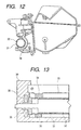
- Figs. 12 and 13 of the accompanying drawings there is shown a case of an example in which a seal member is used.
- Fig. 12 is a front view showing the essential portions of a developing device contained in a process cartridge according to the prior art
- Fig. 13 is a side view showing the essential portions of the developing device.
- a developing sleeve 31 carrying a developer thereon has a magnet roller 32 disposed therein.
- the developing sleeve 31 is rotatably supported by a developing container 30 through a sleeve bearing 35 provided at a predetermined location on the developing container 30 containing a developer therein, and the developer supplied from the developing container 30 may adhere to the surface of the developing sleeve 31 by the magnetic force of the magnet roller 32, and the thickness of the developer layer may be regulated to a predetermined thickness by a developing blade 33 bearing against the developing sleeve 31.
- the developer may be conveyed to a developing area which is a position opposed to a latent image on a photosensitive drum disposed at a location opposed to the developing sleeve 31 with the rotation of the developing sleeve 31, and the developer conveyed to the developing are may adhere to the latent image, whereby developing may be effected.
- an elastic seal member 36 is mounted on the developing container 30 side of the developing sleeve 31 mounted on the developing container 30 at the lengthwisely opposite ends outside the developing area of the developing sleeve 31.
- This elastic seal member 36 is formed into a substantially arcuate cross-sectional shape along the outer peripheral surface of the developing sleeve 31, for example, by felt, formed rubber or the like, and the elastic seal member 36 is brought into pressure contact with the outer peripheral surface of the developing sleeve 31 to thereby prevent the developer from flowing from the surface of the developing sleeve 31 to the lengthwise end portion thereof.
- the elastic seal member 36 is in pressure contact with substantially a half of the outer peripheral surface of the opposite end portions of the developing sleeve 31. So, this has led to a problem that the load of the developing sleeve 31 rotated during the developing operation and the elastic seal member 36 is deteriorated by its contact with the developing sleeve 31, and there is another problem that the toner, though slightly, enters from the gap between the developing sleeve 31 and the elastic seal member 36. These problems have caused torque to become high and the fluctuation of the torque has become great to cause the irregularity of rotation, and this has adversely affected image formation.
- FIG. 14 of the accompanying drawings shows a front view of a developing device using magnet seal members which is known from JP-A-08 030 094 or US-A-5 187 326.
- Each of the magnet seal members 37 provided at the opposite ends of a developing sleeve 31 is a magnet formed into a substantially arcuate cross-sectional shape along the outer periphery of the developing sleeve 31, and has many N and S poles magnetized on the inner peripheral surface thereof.
- the magnet seal members 37 are disposed with a predetermined gap g relative to the outer peripheral surface of the developing container side at the opposite end portions of the developing sleeve 31 having a magnet roller 32 therein, and is mounted on the developing container with the developing sleeve 31 while keeping the gap g.
- the magnet seal members 37 have magnetic poles provided on the inner peripheral surfaces thereof at locations opposed to the magnetic poles of the magnet roller.
- magnet seal members 37 restrain a developer between the end portions of the developing sleeve and the magnet seal member by a magnetic field formed by the magnet roller 32 in the developing sleeve 31 and the magnet seal members 37 to form a seal portion. And the developer which has moved to the lengthwise end portion of the developing sleeve can be blocked by the seal portion to thereby prevent the outflow of the developer from the end portions of the developing sleeve.
- the developing sleeve and the magnet seal members are kept in non-contact with each other and the rotational torque of the developing sleeve becomes remarkably small and therefore, a driving motor may be a compact and inexpensive one. Also, the fluctuation of the rotational torque is small and it becomes difficult for the irregularity of the rotation of the developing sleeve and the photosensitive drum to occur and there is not the wear or the like of the magnet seal members and therefore, the use thereof is semipermanent and the recycle thereof can also coped with.
- the developer carried on the developing sleeve moves in a great deal to the lengthwise end portions of the developing sleeve with the rotation of the developing sleeve, and this has led to the arising of the problem that the developer which has thus moved slips through the seal portions formed between the end portions of the developing sleeve and the magnet seal members.
- this object is achieved by a developing device having the feature of claim 1.
- a developer is prevented from slipping through a magnetic seal.
- Fig. 1 is a schematic view showing the essential portions of an image forming apparatus utilizing a transfer type electrophotographic process of the process cartridge mounting and dismounting type having a developing device to which the present invention is applied.
- a process cartridge 10 removably installed in an image forming apparatus such as a laser printer is comprised of a photosensitive drum 1 which is an electrophotographic photosensitive member of a rotatable photosensitive drum type as an image bearing member on the surface of which an electrostatic latent image is formed disposed so as to be capable of being rotatively driven in a clockwise direction.
- three process instruments i.e., a charging device 2, a developing device 3 and a cleaning device 6, are collectively disposed around the photosensitive drum 1 at predetermined locations in a cartridge housing 9.
- the above-described process cartridge 10 when mounted in a predetermined manner with respect to the body of the image forming apparatus, becomes such that the process cartridge 10 side and the image forming apparatus body side becomes mechanically and electrically coupled to each other and the underside of the photosensitive drum 1 of the process cartridge 10 comes to bear against a transfer roller 4 disposed in the image forming apparatus body, and the apparatus becomes capable of executing image formation. Also, design is made such that when the process cartridge 10 is installed in the image forming apparatus, a process cartridge insertion guiding and holding portion 8 on the image forming apparatus body side bears against a predetermined location on the cartridge housing 9.
- the above-described process cartridge is such that charging means, developing means or cleaning means and a photosensitive drum are integrally made into a cartridge which is removably mountable with respect to the image forming apparatus body.
- this is not restrictive, and at least one of the charging means, the developing means and the cleaning means and the photosensitive drum can be integrally made into a cartridge which is removably mountable in the image forming apparatus body.
- at least the developing means and the photosensitive drum may be integrally made into a cartridge which is removably mountable in the image forming apparatus body.
- the photosensitive drum 1 is uniformly charged by the charging device 2, whereafter correspondingly to an image information signal, the surface of the photosensitive drum 1 is exposed to a laser beam from image exposure means E provided outside the process cartridge 10 and image exposure is effected, whereby an electrostatic latent image is formed on the photosensitive drum 1.
- the electrostatic latent image formed on the photosensitive drum 1 is developed by the developing device 3.
- This visualized image is transferred onto a transfer material at a transfer portion which is the opposed portion of the photosensitive drum 1 and a transfer roller 4 as transfer means disposed at a location opposed to the photosensitive drum 1 which is outside the process cartridge, by the transfer roller 4 and by an electrostatic force and pushing pressure.
- the transfer material onto which the image has been transferred is conveyed to a fixating device 5 of a heat fixation type or the like, whereby the visualized image on the transfer material is fixated, and the transfer material is discharged as an image-formed article (a print or a copy) out of the apparatus.
- the surface of the photosensitive drum may be cleaned with an adhering contaminant such as residual toner on the photosensitive drum 1 removed and may be repetitively used for image formation.
- the peripheral velocity of the photosensitive drum 1 was 94 mm/sec., the outer diameter thereof was 30 mm, the peripheral velocity of a developing sleeve 31 was 111 mm/sec., and the outer diameter of the developing sleeve 31 was 16 mm.
- the direction of rotation of the sleeve 31 was a forward direction relative to the photosensitive drum 1.
- the spacing between the photosensitive drum 1 and the developing sleeve 31 was 0.3 mm.
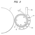
- FIG. 2 is an illustration, partly in cross-section, showing the essential portions of the developing device
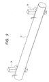
- Fig. 3 is a perspective view of the developing sleeve and magnet seal members
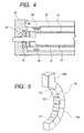
- Fig. 4 is a lengthwise illustration, partly in cross-section, of the essential portions of the developing device
- Fig. 5 is a perspective view showing the magnetization pattern of the magnet seal member.
- the developing sleeve 31 which is a developer carrying member which can carry and convey a magnetic toner which is a magnetic developer on the surface thereof is disposed in an opening portion provided at a location on a developing container 30 containing the magnetic toner therein which is opposed to the photosensitive drum 1, and a regulating blade 33 as developer layer thickness regulating means bears against the surface of the developing sleeve 31.
- magnet seal members 34 for regulating the movement of the toner carried on the developing sleeve 31 in the lengthwise direction of the developing sleeve 31 are disposed in non-contact with the developing sleeve 31, and an agitating device or the like for agitating the toner is provided in the developing container 30, whereby the developing device 3 is constituted.
- the developing sleeve 31 use is made of a non-magnetic cylindrical sleeve formed of aluminum, stainless steel or the like.
- the developing sleeve 31 disposed in the opening portion of the developing container 30 is rotatably held through a sleeve bearing 35 provided at a predetermined location in the developing container 30.
- a magnet roller 32 which is a roller-like magnet is fixedly disposed in the developing sleeve 31.
- the developing sleeve 31 is rotatable in a counter-clockwise direction.
- the magnet roller 32 disposed in the developing sleeve 31 has a plurality of magnetic poles, i.e., two N poles N1 and N2 and two S poles S1 and S2, on the surface thereof, and design is made. Accordingly, the developing sleeve 31 can be rotated in the counter-clockwise direction to cause the magnetic toner supplied in the developing container 30 to adhere to the surface of the developing sleeve by the magnetic force of the magnet roller 32 and convey the magnetic toner toward the photosensitive drum.
- the surface of the developing sleeve 31 is pressed in the opening portion of the developing container 30 by the regulating blade 33 bearing against the surface of the developing sleeve 31 to thereby regulate the amount of the developer on the developing sleeve 31 and regulate the thickness of the developer layer carried and conveyed to a developing area in which the developing sleeve and the photosensitive drum are opposed to each other.
- the magnetic toner having had its layer thickness regulated by the regulating blade 33 and carried on and conveyed by the developing sleeve 31 can visualize and develop the electrostatic latent image formed on the photosensitive drum 1 rotated in a clockwise direction.
- a vibration bias voltage comprising a DC voltage superposed on an AC voltage is applied to the developing sleeve 31.
- a rectangular wave, a sine wave or the like can be used as the waveform of the vibration bias voltage.
- each of magnet seal member 34 disposed on the opposite ends of the developing sleeve 31 has N and S poles magnetized into multiple magnetic poles and formed on the inner surface thereof. Specifically, it has four S poles S11, S12, S13 and S14 and three N poles N11, N12 and N13 on the inner surface thereof, and the S and N poles are alternately disposed.
- the pole S2 of the magnet roller 32 and the pole N12 of the magnet seal member 34 are disposed in opposed relationship with each other, and the magnetic poles of the magnet roller 32 and the magnetic poles of the magnet seal members 34 together can form an N-S forward magnetic field.
- the peak value of the magnetic-flux density of each magnetic pole of the magnet roller 32 fixed in the developing sleeve 31 on the surface of the sleeve in the direction of a normal to the surface of the sleeve was 400 ⁇ 10 -4 to 900 ⁇ 10 -4 T(tesla).
- the magnet seal members 34 were injection-molded articles of a width 4mm provided with a nylon binder containing magnetic powder of Nd(neodymium)-Fe-B(boron), and the spacing g between the magnet seal members 34 and the developing sleeve 31 were 0.1 to 0.7 mm.
- the peak value of the magnetic-flux density of each magnetic pole of the magnet seal members 34 on the surface of the sleeve in the direction of a normal to the surface of the sleeve was 1000 ⁇ 10 -4 to 2200 ⁇ 10 -4 T(tesla).
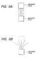
- Figs. 6A and 6B are typical views representing the distribution of the lines of magnetic force by an opposed magnetic pole.
- Fig. 6A shows a case where the opposed magnetic pole is present
- Fig. 6B shows a case where the opposed magnetic pole is absent.
- Fig. 6A generally, when there is an opposed magnetic pole to a certain magnetic pole, lines of magnetic force concentrate in a direction perpendicular to the magnetic pole and therefore, if there is a toner near the lines of magnetic force, the magnetic toner will be arranged along these lines of magnetic force.
- Fig. 6B there is no opposed magnetic pole, lines of magnetic force are diffused in oblique directions and becomes sparse. The magnetic toner is arranged along these lines of magnetic force.
- magnet seal members are disposed on the end portions of the developing sleeve. And when opposed magnetic poles are constructed by the magnet in the sleeve and the magnet seal members to thereby concentrate lines of magnetic force and seal, if the developing sleeve is rotated with the developer carried on the surface thereof, the magnetic toner on the developing sleeve will move toward the end portions by the diffusing action and be checked at the locations of the magnet seal members. Certainly, by concentrating the lines of magnetic force as shown in Fig. 6A, the leakage of the developer by a shock or the like can be suppressed and prevented, but in some cases, the sealing property to the diffusing action of the magnetic toner by the rotation of the developing sleeve is not always sufficient.
- the leakage of the developer can also be suppressed and prevented by adjusting the values of the magnitude Fr1 of the magnetic force by the magnet roller 32 in the direction of the normal to the surface of the developing sleeve and the magnitude Fr2 of the magnetic force by the magnet seal member at the same position in the direction of the normal to the surface of the developing sleeve.
- the sealing property can be made good.
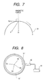
- Fig. 7 is an illustration of the essential portions for illustrating the magnetic force Fr on the developing sleeve.
- F indicates the magnetic force on the developing sleeve 31
- Fr indicates the magnetic force on the developing sleeve 31 in the direction of the normal to the surface of the sleeve
- F ⁇ indicates the magnetic force on the developing sleeve 31 in the tangential direction of the surface of the sleeve.
- Br(r) is the magnetic-flux density [gauss] on the developing sleeve in the direction of the normal
- Br(r+ ⁇ r) is the magnetic-flux density [gauss] at a height of 0.2 mm over the developing sleeve in the direction of the normal
- B ⁇ (r) is the magnetic-flux density [gauss] on the developing sleeve in the tangential direction
- B ⁇ (r+ ⁇ r) is the magnetic-flux density [gauss] at a height of 0.2 mm over the developing sleeve in the tangentia direction.
- the relative magnitude of the magnetic force Fr can be known, and the form of distribution of the magnetic force Fr, the peak position of the magnetic force Fr, etc. can be known.
- r was the radius of the developing sleeve
- ⁇ r was 0.2 mm
- the magnetic-flux densities Br(r), Br(r+ ⁇ r), B ⁇ (r) and B ⁇ (r+ ⁇ r) were measured by the use of the gauss meter of Bell, Inc. which will be described later, and from the result of the measurement, ⁇ B2(r)-B2(r+ ⁇ r) ⁇ was found by calculation and the relative value of the magnetic force Fr was found.
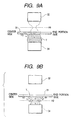
- FIG. 8 is a schematic view showing a method of measuring the magnetic-flux density on the developing sleeve or at a position of 2 mm over the sleeve in the direction of the normal and the magnetic-flux density in the tangential direction with the magnet roller being single (the magnet seal members being not opposed thereto).
- the gauss meter model 9903 of Bell, Inc. was used for the measurement. Also, design was made such that the developing sleeve 31' and the gauss meter were horizontally fixed and the magnet roller 32' in the sleeve was rotatably disposed.
- the measuring surface of the two-axis type probe 42 (YOA99-1802 produced by Bell, Inc.) is disposed with some spacing kept with respect to the surface of the developing sleeve 31', and is fixed so that the center of the developing sleeve 31' and the center of the probe 42 may be on substantially the same horizontal plane, and the probe 42 is connected to the gauss meter 41. So, the magnetic-flux densities on the developing sleeve 31' or at a position of 0.2 mm over the sleeve in the direction of the normal and the tangential direction can be measured.
- the developing sleeve 31' and the magnet roller 32' are disposed substantially concentrically with each other, and the spacing between the developing sleeve 31' and the magnet roller 32' may be considered to be equal at any point. Accordingly, by the magnet roller 32' being rotated, the magnetic-flux densities on the developing sleeve 31' or at a position of 0.2 mm over the sleeve in the direction of the normal and the tangential direction can be measured relative to all of the peripheral directions of the sleeve. Also, the magnet roller 32' has magnetic poles N1, S2, N2 and S1 disposed at a predetermined angle and is rotated in the direction of arrow of Fig.
- the angle of the magnetic pole S2 assumes a greater value than the angle of the magnetic pole N1. That is, the measurement was effected in a direction in which the downstream side increases in angle relative to the counter-clockwise direction which is the direction of movement of the sleeve in Fig. 1.
- the magnetic force of the magnet seal members when the magnet seal members 34 were single (the magnet roller is absent) was found by fixing the magnet seal members onto a rotatable table, fixing the above-described probe with a predetermined spacing kept with respect to the magnet seal members, and rotating the rotatable table to thereby likewise measure the magnetic-flux densities on the developing sleeve 31 or at a position of 0.2 mm over the sleeve in the direction of the normal and the tangential direction.
- the magnetic force Fr on the developing sleeve was variously changed and observed, and as the result, it has been found that the sealing property when the developing device is durably used is related to the magnetic force on the developing sleeve 31.
- the magnetic-flux density on the surface of the developing sleeve was measured with the magnet seal members disposed on the developing sleeve
- the magnetic-flux density at the surface position of the developing sleeve for the magnet seal members singly and the magnet roller 32 singly was measured and each magnetic force was calculated from this magnetic-flux density and the magnitudes of these magnetic forces were compared with each other, it has been found that the magnitude of the magnetic force is related to the sealing property when the developing device is durably used.
- the sealing property can be made good by forming the magnet roller and the magnet seal members so that the magnitude Fr2 of the magnetic force for the magnet seal members singly in the direction of the normal to the surface position of the developing sleeve may become sufficiently greater than the magnitude Fr1 of the magnetic force in the direction of the normal to the surface position of the developing sleeve in an area opposed to the magnet seal members for the magnet roller 32 singly in the developing sleeve.
- the diffusion and movement of the magnetic toner on the lengthwisely central side of the sleeve toward the end portion can be prevented during the time until the magnetic toner supplied from the developing container to the opening portion returns into the developing container.
- the magnetic toner diffused and moved in the lengthwise direction by the rotation of the sleeve collides with the stagnant and held magnetic toner and is checked thereby and is attracted to the magnet seal member 34 side and therefore, is attracted back in a direction indicated by arrow in Fig. 9A, i.e., toward the lengthwisely central side of the developing sleeve, thereby deterring the movement toward the end portion.
- the magnetic toner is attracted to the magnet seal member 34 side and therefore the diffusion and movement thereof can be prevented. And even if it is once moved to the end portion side, it is attracted to the magnet seal member 34 side and collects there and therefore, by the collecting toner, a blocking force works and further diffusion can be prevented.
- the magnetic force Fr on the developing sleeve 31 is attracted to and acts on the magnet roller 32 side
- the magnetic force Fr in the direction of the normal between the magnet seal member 34 and the magnet roller 32 has a balancing point between the developing sleeve 31 and the magnet seal member 34.
- this balancing position is H2
- a force attracted to the developing sleeve 31 side works on the side more adjacent to the developing sleeve 31 than to the balancing position H2 of the magnetic force Fr
- a force attracted to the magnet seal member 34 side works on the side more adjacent to the magnet seal member 34 than to the balancing position H2.
- the magnetic toner held in the area wherein the magnet seal member and the magnet roll are opposed to each other is attracted neither to the magnet seal member 34 nor to the magnet roller 32 at the balancing position H2 (located between the surface of the developing sleeve and the magnet seal member) of the magnetic force Fr, and the amount of restrained toner is small and the seal is in a thin state.
- the magnetic toner diffused and moved in the lengthwise direction of the sleeve by the rotation of the sleeve collides with the stagnant and held magnetic toner and rides onto the stagnant magnetic toner, and slips through the thin portion of the seal at the balancing position H2 of the magnetic force Fr and moves toward the end portion, whereby the slipping-through of the developer occurs.
- the toner on the end portion side of the lump of the magnetic toner stagnant and held on the developing sleeve 31 may sometimes be moved toward the end portion by the diffusing action.
- the magnetic pole construction of the magnet roller in the lengthwisely intermediate developing area of the developing sleeve is set by a developing characteristic, a developer conveying property, etc.. Accordingly, only the portion opposed to the magnet seal members is made into a special magnetic pole construction, the cost of the magnet roller will become higher and therefore, it is advantageous to make this portion also into the same construction as that of the central portion.
- the magnet seal member 34 is disposed near the poles N1, S2 and N2 of the magnet roller 32, and a lump of magnetic toner is held in this area so as to form a nip portion and seal it. Also, generally, the intervals among the magnetic poles of the magnet roller 32 are wide.
- the magnetic poles of the magnet seal member 34 are disposed in opposed relationship with the magnetic poles of the magnet roller 32 to thereby form an N-S forward magnetic field, and the magnetic force of the magnet seal member 34 is made greater than the magnetic force of the magnet roller 32, whereby the slipping-through of the developer by the diffusion and movement of the toner and the leakage of the toner by a strong shock can be suppressed and prevented, and the magnetic poles of the magnet seal member 34 are disposed among the magnetic poles of the magnet roller 32 and the magnetic toner is restrained by the magnet seal member 34, whereby the sealing property is made good to among the magnetic poles as well.
- the magnet seal member 34 has poles S11, N12 and S14 disposed at locations opposed to the three magnetic poles N1, S2 and N2, respectively, of the magnet roller 32 in the developing sleeve 31, and cooperates with the magnet roller 32 to form an N-S magnetic field. Further, poles N11, S12 and poles S13, N13 are disposed at locations opposed to between the magnetic poles N1-S2 of the magnet roller 32 and to between the magnet poles S2-N2 of the magnet roller 32, respectively.
- N and S poles are magnetized to multiple magnetic poles on the inner peripheral surface of the magnet seal member 34, and also on the magnetic poles N11, S12, S13 and N13 of the magnet seal member 34, the magnetic toner is restrained so that the sealing property can be made good.
- a magnetic field comprising a magnetic field in the direction of the normal between adjacent magnetic poles of the magnet seal member 34 and a magnetic field in the tangential direction combined together is made great and by the action of this magnetic field, the magnetic toner is restrained, whereby the sealing property between adjacent magnetic poles can be made good.
- the magnet seal member 34 is formed so that the value of the magnetic-flux density B at the position between the magnetic poles on the surface of the developing sleeve 31 singly by the magnet seal member 34 (a state in which it is not disposed on the developing sleeve) may be 80% or greater and 120% or less, and more preferably 90% or greater and 100% or less, of the value of the magnetic-flux density B of the magnetic pole position on the surface of the developer carrying member singly by the magnet seal member.
- Br is the magnetic-flux density [gauss] on the developing sleeve in the direction of the normal
- B ⁇ is the magnetic-flux density [gauss] on the developing sleeve in the tangential direction.
- the magnetic-flux density Br and the magnetic-flux density B ⁇ were measured by the use of the gauss meter and two-axis probe of the above-mentioned Bell Inc.
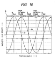
- Fig. 10 represents the magnetic pole positions and the form of distribution of magnetic-flux density at the surface position of the developing sleeve by the magnet seal member singly, in case where the magnet seal member of the present embodiment is provided with magnetic poles at the locations opposed to the magnetic poles of the magnet roller and among the magnetic poles.
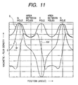
- Fig. 11 represents the magnetic poles positions and the form of distribution of magnetic-flux density at the surface position of the developing sleeve by a magnet seal member singly, in case where the magnet seal member of the prior art is provided with magnetic poles only at locations opposed to the magnetic poles of the magnet roll.
- the axis of abscissas of each graph indicates the positions in the circumferential direction of the developing sleeve 31 by angles, and the axis of ordinates indicates the magnitudes of the magnetic-flux densities B, Br and B ⁇ on the sleeve.
- the magnetic-flux density B thereof is considerably lower than the magnetic-flux density B of the magnetic pole portion and the sealing property of that portion cannot be expected.
- the magnetic-flux density B between magnetic poles and the magnetic-flux density B of the magnetic pole portion are of substantially the same degree of magnitude. From this, it will be seen that as in the present embodiment, the magnetic-flux density B between magnetic poles is made great, whereby the sealing property can be made good to between magnetic poles as well.
- the magnitude of the magnetic force Fr singly by the magnet seal member in the direction of the normal to the surface position of the developing sleeve is made greater than the magnitude of the magnetic force Fr singly by the magnet roller in the direction of the normal to the surface position of the developing sleeve in an area opposed to the magnet seal member.
- the magnet roller 32 used in the present embodiment can be a conventional magnet such as a ferrite magnet, an alnico magnet, an iron cobalt magnet or a rare earth magnet, and from the viewpoints of cost and weight, it is preferable that minute ferrite magnets dispersed in resin or rubber be formed as a magnet.
- the magnet seal member 34 use can be made of the above-mentioned conventional magnet used as the magnet roll, but it may preferably be formed by a rare earth magnet in that a hight magnetic field is obtained.
- the magnet roller 32 and the magnet seal member 34 may be formed by different kinds of magnets, and a ferrite magnet may be used as the magnet roller 32 and a rare earth magnet may be used as the magnet seal member 34, whereby by a simple construction, the magnetic force of the magnet seal member can be made greater than that of the magnet roller 32, and it becomes possible to suppress and prevent the slipping-through of the developer better, or suppress and prevent the leakage of the developer by a shock or the like better.
- the magnetic force of the magnet seal member can be made very great, and the slipping-through of the developer can be suppressed and prevented or the leakage of the developer by a shock or the like can be suppressed and prevented.
- the above embodiment has been described with respect to a case where a magnetic toner is used as the magnetic developer in the developing device, but the use of a two-component magnetic developer comprising a non-magnetic toner and magnetic particles (carrier) as the developer also leads to the obtainment of a similar effect.
- the developing device of each construction according to the present embodiment is provided in a process cartridge, whereas this is not restrictive, but the developing device of each described construction can also be disposed in an image forming apparatus.
Landscapes
- Physics & Mathematics (AREA)
- General Physics & Mathematics (AREA)
- Dry Development In Electrophotography (AREA)
- Magnetic Brush Developing In Electrophotography (AREA)
- Electrophotography Configuration And Component (AREA)
Claims (6)
- Entwicklungsvorrichtung mit:wobei an Abschnitten gegenüberliegend jedes Magnetpols des Entwickler-Tragemagneten (32) in einem Dichtungsbereich des magnetischen Dichtungsteils auf einer Oberfläche des Entwickler-Trageteils (31) eine Größe Fr1 einer durch den Entwickler-Tragemagneten (32) erzeugten Magnetkraft in einer lotrechten Richtung kleiner als eine Größe Fr2 einer durch das magnetische Dichtungsteil (34) erzeugten Magnetkraft in einer lotrechten Richtung ist.einem Entwickler-Behälter (30), welcher darin einen magnetischen Entwickler enthält;einem Entwickler-Trageteil (31), welches in einem Öffnungsabschnitt des Entwickler-Behälters zum Tragen und Befördern des Entwicklers darauf bereitgestellt ist;einem Entwickler-Tragemagneten (32), welcher unbewegbar im Entwickler-Trageteil bereitgestellt ist, um das Entwickler-Trageteil zu bewirken durch seine eigene magnetische Kraft den Entwickler darauf zu tragen; undeinem magnetischen Dichtungsteil (34), welches angrenzend zu Endabschnitten des Entwickler-Trageteils (31) bereitgestellt ist, um eine Abdichtung des Entwicklers durch seine eigene magnetische Kraft zu bewirken,
- Entwicklungsvorrichtung nach Anspruch 1, bei welcher das magnetische Dichtungsteil (34) an Abschnitten, welche im wesentlichen den Magnetpolen des Entwickler-Tragemagneten (32) gegenüberliegen, Magnetpole von unterschiedlichen Polaritäten hat.
- Entwicklungsvorrichtung nach Anspruch 1, bei welcher das magnetische Dichtungsteil (34) entlang der Umfangsrichtung des Entwickler-Trageteils (31) mit einem vorbestimmten Spalt dazwischen bereitgestellt ist.
- Entwicklungsvorrichtung nach Anspruch 1, bei welcher der magnetische Entwickler ein magnetischer Ein-Komponenten Toner ist.
- Entwicklungsvorrichtung nach Anspruch 1, bei welcher die Entwicklungsvorrichtung zusammen mit einem bildtragenden Teil bereitgestellt ist, welches einen Entwicklungsbetrieb auf einer Bilderzeugungseinrichtung bewirkt.
- Entwicklungsvorrichtung nach Anspruch 1, wobei die Größe Fr1 über den gesamten Dichtungsbereich des magnetischen Dichtungsteils (34) kleiner ist als die Größe Fr2.
Applications Claiming Priority (3)
| Application Number | Priority Date | Filing Date | Title |
|---|---|---|---|
| JP265121/97 | 1997-09-12 | ||
| JP26512197A JP3927661B2 (ja) | 1997-09-12 | 1997-09-12 | 現像装置、プロセスカートリッジおよび画像形成装置 |
| JP26512197 | 1997-09-12 |
Publications (3)
| Publication Number | Publication Date |
|---|---|
| EP0902336A2 EP0902336A2 (de) | 1999-03-17 |
| EP0902336A3 EP0902336A3 (de) | 2000-06-14 |
| EP0902336B1 true EP0902336B1 (de) | 2004-12-01 |
Family
ID=17412916
Family Applications (1)
| Application Number | Title | Priority Date | Filing Date |
|---|---|---|---|
| EP98117171A Expired - Lifetime EP0902336B1 (de) | 1997-09-12 | 1998-09-10 | Entwicklungsvorrichtung |
Country Status (6)
| Country | Link |
|---|---|
| US (1) | US6032007A (de) |
| EP (1) | EP0902336B1 (de) |
| JP (1) | JP3927661B2 (de) |
| CN (1) | CN1105336C (de) |
| AU (1) | AU734773B2 (de) |
| DE (1) | DE69827889T2 (de) |
Families Citing this family (15)
| Publication number | Priority date | Publication date | Assignee | Title |
|---|---|---|---|---|
| JP3363873B2 (ja) | 1999-07-13 | 2003-01-08 | キヤノン株式会社 | 現像剤量逐次表示方法及び電子写真画像形成装置 |
| JP3943772B2 (ja) | 1999-08-06 | 2007-07-11 | キヤノン株式会社 | 現像装置、プロセスカートリッジ及び電子写真画像形成装置 |
| JP2001051490A (ja) | 1999-08-06 | 2001-02-23 | Canon Inc | 現像装置、プロセスカートリッジ及び電子写真画像形成装置 |
| JP2001255786A (ja) | 2000-01-07 | 2001-09-21 | Canon Inc | 電子写真画像形成装置 |
| JP2001290355A (ja) | 2000-04-06 | 2001-10-19 | Canon Inc | 現像装置、プロセスカートリッジ及び電子写真画像形成装置 |
| US6697578B2 (en) | 2000-08-25 | 2004-02-24 | Canon Kabushiki Kaisha | Memory member, unit, process cartridge and electrophotographic image forming apparatus |
| JP2002196647A (ja) | 2000-12-22 | 2002-07-12 | Canon Inc | プロセスカートリッジ及び画像形成装置 |
| JP2002258720A (ja) | 2001-03-05 | 2002-09-11 | Canon Inc | 電子写真画像形成装置及びプロセスカートリッジ |
| JP2003241606A (ja) | 2002-02-20 | 2003-08-29 | Canon Inc | プロセスカートリッジ及びクリーニング装置 |
| JP3854897B2 (ja) * | 2002-05-21 | 2006-12-06 | キヤノン株式会社 | 現像装置及びプロセスカートリッジ及び画像形成装置 |
| JP4217474B2 (ja) * | 2002-12-20 | 2009-02-04 | キヤノン株式会社 | 磁性体シール部材、これを用いた現像装置、プロセスカートリッジ及び電子写真画像形成装置 |
| JP2004205950A (ja) * | 2002-12-26 | 2004-07-22 | Canon Inc | クリーニング装置、プロセスカートリッジおよび画像形成装置 |
| JP5430162B2 (ja) * | 2009-01-30 | 2014-02-26 | キヤノン株式会社 | 現像装置 |
| JP6855284B2 (ja) | 2017-03-03 | 2021-04-07 | キヤノン株式会社 | カートリッジ及び画像形成装置 |
| CN112433185A (zh) * | 2020-12-08 | 2021-03-02 | 西南大学 | 一种基于强磁显影的果树育种及苗木追溯方法及装置 |
Family Cites Families (11)
| Publication number | Priority date | Publication date | Assignee | Title |
|---|---|---|---|---|
| DE2816621C3 (de) * | 1978-04-17 | 1980-10-09 | Lumoprint Zindler Kg (Gmbh & Co), 2000 Hamburg | Dichtungsanordnung in einer Entwicklungsvorrichtung eines Kopiergeräte |
| JPH0313977A (ja) * | 1989-06-13 | 1991-01-22 | Canon Inc | 現像装置 |
| JP2899079B2 (ja) * | 1990-07-10 | 1999-06-02 | キヤノン株式会社 | 現像装置 |
| JPH04136965A (ja) * | 1990-09-28 | 1992-05-11 | Canon Inc | 現像装置 |
| JPH07281528A (ja) * | 1994-04-04 | 1995-10-27 | Canon Inc | 画像形成装置の現像装置 |
| JP3074114B2 (ja) * | 1994-07-12 | 2000-08-07 | キヤノン株式会社 | 現像装置及びプロセスカートリッジ |
| JP3013977B2 (ja) | 1994-11-10 | 2000-02-28 | ソニー株式会社 | 移動体管理システム |
| JPH08137275A (ja) * | 1994-11-10 | 1996-05-31 | Canon Inc | 画像形成装置及びプロセスカートリッジ |
| JPH08202153A (ja) * | 1995-01-31 | 1996-08-09 | Canon Inc | 現像装置 |
| JP3372747B2 (ja) * | 1996-02-09 | 2003-02-04 | キヤノン株式会社 | 現像装置 |
| JP3323749B2 (ja) * | 1996-08-01 | 2002-09-09 | キヤノン株式会社 | 磁気シール装置及び現像装置並びに画像形成装置 |
-
1997
- 1997-09-12 JP JP26512197A patent/JP3927661B2/ja not_active Expired - Fee Related
-
1998
- 1998-09-03 US US09/146,357 patent/US6032007A/en not_active Expired - Lifetime
- 1998-09-10 EP EP98117171A patent/EP0902336B1/de not_active Expired - Lifetime
- 1998-09-10 DE DE69827889T patent/DE69827889T2/de not_active Expired - Lifetime
- 1998-09-11 AU AU84209/98A patent/AU734773B2/en not_active Ceased
- 1998-09-14 CN CN98119248A patent/CN1105336C/zh not_active Expired - Fee Related
Also Published As
| Publication number | Publication date |
|---|---|
| EP0902336A3 (de) | 2000-06-14 |
| AU8420998A (en) | 1999-03-25 |
| DE69827889T2 (de) | 2005-11-24 |
| US6032007A (en) | 2000-02-29 |
| AU734773B2 (en) | 2001-06-21 |
| EP0902336A2 (de) | 1999-03-17 |
| JP3927661B2 (ja) | 2007-06-13 |
| CN1105336C (zh) | 2003-04-09 |
| DE69827889D1 (de) | 2005-01-05 |
| JPH1184871A (ja) | 1999-03-30 |
| CN1214472A (zh) | 1999-04-21 |
Similar Documents
| Publication | Publication Date | Title |
|---|---|---|
| EP0902336B1 (de) | Entwicklungsvorrichtung | |
| US5812909A (en) | Developing device | |
| US5177536A (en) | Developing apparatus having a magnetic seal | |
| US7725061B2 (en) | Developing apparatus | |
| JPH0384573A (ja) | 現像装置 | |
| US20060067730A1 (en) | Developing device, process cartridge, and image forming apparatus | |
| US7231168B2 (en) | Image forming apparatus | |
| US5359397A (en) | Developing apparatus | |
| US8422909B2 (en) | Developing apparatus | |
| US6785498B2 (en) | Development system for developing an image on an image bearing member | |
| US5523533A (en) | Developing device which restricts carrier using developing agent regulating rotary member | |
| US5754929A (en) | Development apparatus | |
| JP3902848B2 (ja) | 現像装置、プロセスカートリッジおよび画像形成装置 | |
| JP3544062B2 (ja) | 磁気ブラシ帯電装置及び画像形成装置 | |
| JPH01120581A (ja) | 現像装置 | |
| US6771923B2 (en) | Magnetic core for use in a development system | |
| JP2000330384A (ja) | 現像装置、プロセスカートリッジおよび画像形成装置 | |
| JPH1184869A (ja) | 現像装置、プロセスカートリッジおよび画像形成装置 | |
| JP2000019842A (ja) | 現像装置及びこれを備えたプロセスカートリッジ及び画像形成装置 | |
| JPH11338246A (ja) | 現像装置、プロセスカートリッジ及び画像形成装置 | |
| JPH0384572A (ja) | 電子写真装置 | |
| JPH10339999A (ja) | 現像装置、プロセスカートリッジおよび画像形成装置 | |
| JP2727095B2 (ja) | 現像装置 | |
| JP2000162869A (ja) | 現像装置及びこの現像装置を備えるプロセスカートリッジ並びに画像形成装置 | |
| JP2000172071A (ja) | 現像装置及びプロセスカートリッジ |
Legal Events
| Date | Code | Title | Description |
|---|---|---|---|
| PUAI | Public reference made under article 153(3) epc to a published international application that has entered the european phase |
Free format text: ORIGINAL CODE: 0009012 |
|
| AK | Designated contracting states |
Kind code of ref document: A2 Designated state(s): CH DE FR GB IT LI |
|
| AX | Request for extension of the european patent |
Free format text: AL;LT;LV;MK;RO;SI |
|
| PUAL | Search report despatched |
Free format text: ORIGINAL CODE: 0009013 |
|
| AK | Designated contracting states |
Kind code of ref document: A3 Designated state(s): AT BE CH CY DE DK ES FI FR GB GR IE IT LI LU MC NL PT SE |
|
| AX | Request for extension of the european patent |
Free format text: AL;LT;LV;MK;RO;SI |
|
| 17P | Request for examination filed |
Effective date: 20001026 |
|
| AKX | Designation fees paid |
Free format text: CH DE FR GB IT LI |
|
| 17Q | First examination report despatched |
Effective date: 20030319 |
|
| GRAP | Despatch of communication of intention to grant a patent |
Free format text: ORIGINAL CODE: EPIDOSNIGR1 |
|
| GRAS | Grant fee paid |
Free format text: ORIGINAL CODE: EPIDOSNIGR3 |
|
| GRAA | (expected) grant |
Free format text: ORIGINAL CODE: 0009210 |
|
| AK | Designated contracting states |
Kind code of ref document: B1 Designated state(s): CH DE FR GB IT LI |
|
| PG25 | Lapsed in a contracting state [announced via postgrant information from national office to epo] |
Ref country code: LI Free format text: LAPSE BECAUSE OF FAILURE TO SUBMIT A TRANSLATION OF THE DESCRIPTION OR TO PAY THE FEE WITHIN THE PRESCRIBED TIME-LIMIT Effective date: 20041201 Ref country code: IT Free format text: LAPSE BECAUSE OF FAILURE TO SUBMIT A TRANSLATION OF THE DESCRIPTION OR TO PAY THE FEE WITHIN THE PRESCRIBED TIME-LIMIT;WARNING: LAPSES OF ITALIAN PATENTS WITH EFFECTIVE DATE BEFORE 2007 MAY HAVE OCCURRED AT ANY TIME BEFORE 2007. THE CORRECT EFFECTIVE DATE MAY BE DIFFERENT FROM THE ONE RECORDED. Effective date: 20041201 Ref country code: CH Free format text: LAPSE BECAUSE OF FAILURE TO SUBMIT A TRANSLATION OF THE DESCRIPTION OR TO PAY THE FEE WITHIN THE PRESCRIBED TIME-LIMIT Effective date: 20041201 |
|
| REG | Reference to a national code |
Ref country code: GB Ref legal event code: FG4D |
|
| REG | Reference to a national code |
Ref country code: CH Ref legal event code: EP |
|
| REF | Corresponds to: |
Ref document number: 69827889 Country of ref document: DE Date of ref document: 20050105 Kind code of ref document: P |
|
| REG | Reference to a national code |
Ref country code: CH Ref legal event code: PL |
|
| PLBE | No opposition filed within time limit |
Free format text: ORIGINAL CODE: 0009261 |
|
| STAA | Information on the status of an ep patent application or granted ep patent |
Free format text: STATUS: NO OPPOSITION FILED WITHIN TIME LIMIT |
|
| ET | Fr: translation filed | ||
| 26N | No opposition filed |
Effective date: 20050902 |
|
| REG | Reference to a national code |
Ref country code: FR Ref legal event code: PLFP Year of fee payment: 19 |
|
| PGFP | Annual fee paid to national office [announced via postgrant information from national office to epo] |
Ref country code: DE Payment date: 20160930 Year of fee payment: 19 Ref country code: GB Payment date: 20160914 Year of fee payment: 19 |
|
| PGFP | Annual fee paid to national office [announced via postgrant information from national office to epo] |
Ref country code: FR Payment date: 20160926 Year of fee payment: 19 |
|
| REG | Reference to a national code |
Ref country code: DE Ref legal event code: R119 Ref document number: 69827889 Country of ref document: DE |
|
| GBPC | Gb: european patent ceased through non-payment of renewal fee |
Effective date: 20170910 |
|
| REG | Reference to a national code |
Ref country code: FR Ref legal event code: ST Effective date: 20180531 |
|
| PG25 | Lapsed in a contracting state [announced via postgrant information from national office to epo] |
Ref country code: GB Free format text: LAPSE BECAUSE OF NON-PAYMENT OF DUE FEES Effective date: 20170910 Ref country code: DE Free format text: LAPSE BECAUSE OF NON-PAYMENT OF DUE FEES Effective date: 20180404 |
|
| PG25 | Lapsed in a contracting state [announced via postgrant information from national office to epo] |
Ref country code: FR Free format text: LAPSE BECAUSE OF NON-PAYMENT OF DUE FEES Effective date: 20171002 |