EP0902129A2 - Verfahren und Vorrichtung für den Rohreinbau - Google Patents
Verfahren und Vorrichtung für den Rohreinbau Download PDFInfo
- Publication number
- EP0902129A2 EP0902129A2 EP98116582A EP98116582A EP0902129A2 EP 0902129 A2 EP0902129 A2 EP 0902129A2 EP 98116582 A EP98116582 A EP 98116582A EP 98116582 A EP98116582 A EP 98116582A EP 0902129 A2 EP0902129 A2 EP 0902129A2
- Authority
- EP
- European Patent Office
- Prior art keywords
- shoring
- trench
- plate
- channel
- closure plate
- Prior art date
- Legal status (The legal status is an assumption and is not a legal conclusion. Google has not performed a legal analysis and makes no representation as to the accuracy of the status listed.)
- Granted
Links
- 238000000034 method Methods 0.000 title claims description 17
- 239000000463 material Substances 0.000 claims abstract description 31
- 230000009969 flowable effect Effects 0.000 claims abstract description 4
- 239000002689 soil Substances 0.000 claims description 9
- 239000004567 concrete Substances 0.000 claims description 6
- 239000000945 filler Substances 0.000 claims description 4
- 239000004570 mortar (masonry) Substances 0.000 claims description 4
- 230000008878 coupling Effects 0.000 claims description 3
- 238000010168 coupling process Methods 0.000 claims description 3
- 238000005859 coupling reaction Methods 0.000 claims description 3
- XLYOFNOQVPJJNP-UHFFFAOYSA-N water Substances O XLYOFNOQVPJJNP-UHFFFAOYSA-N 0.000 claims description 3
- 235000008733 Citrus aurantifolia Nutrition 0.000 claims description 2
- 235000011941 Tilia x europaea Nutrition 0.000 claims description 2
- 239000000654 additive Substances 0.000 claims description 2
- 229910000278 bentonite Inorganic materials 0.000 claims description 2
- 239000000440 bentonite Substances 0.000 claims description 2
- SVPXDRXYRYOSEX-UHFFFAOYSA-N bentoquatam Chemical compound O.O=[Si]=O.O=[Al]O[Al]=O SVPXDRXYRYOSEX-UHFFFAOYSA-N 0.000 claims description 2
- 239000004568 cement Substances 0.000 claims description 2
- 239000004571 lime Substances 0.000 claims description 2
- 238000009415 formwork Methods 0.000 description 3
- 238000009434 installation Methods 0.000 description 3
- 238000009412 basement excavation Methods 0.000 description 2
- 238000007789 sealing Methods 0.000 description 2
- 230000015572 biosynthetic process Effects 0.000 description 1
- 238000010276 construction Methods 0.000 description 1
- 238000005516 engineering process Methods 0.000 description 1
- 238000011065 in-situ storage Methods 0.000 description 1
- 239000002184 metal Substances 0.000 description 1
- 239000011178 precast concrete Substances 0.000 description 1
- 239000004576 sand Substances 0.000 description 1
Images
Classifications
-
- E—FIXED CONSTRUCTIONS
- E02—HYDRAULIC ENGINEERING; FOUNDATIONS; SOIL SHIFTING
- E02F—DREDGING; SOIL-SHIFTING
- E02F5/00—Dredgers or soil-shifting machines for special purposes
- E02F5/02—Dredgers or soil-shifting machines for special purposes for digging trenches or ditches
- E02F5/12—Dredgers or soil-shifting machines for special purposes for digging trenches or ditches with equipment for back-filling trenches or ditches
-
- E—FIXED CONSTRUCTIONS
- E02—HYDRAULIC ENGINEERING; FOUNDATIONS; SOIL SHIFTING
- E02D—FOUNDATIONS; EXCAVATIONS; EMBANKMENTS; UNDERGROUND OR UNDERWATER STRUCTURES
- E02D17/00—Excavations; Bordering of excavations; Making embankments
- E02D17/06—Foundation trenches ditches or narrow shafts
- E02D17/08—Bordering or stiffening the sides of ditches trenches or narrow shafts for foundations
-
- F—MECHANICAL ENGINEERING; LIGHTING; HEATING; WEAPONS; BLASTING
- F16—ENGINEERING ELEMENTS AND UNITS; GENERAL MEASURES FOR PRODUCING AND MAINTAINING EFFECTIVE FUNCTIONING OF MACHINES OR INSTALLATIONS; THERMAL INSULATION IN GENERAL
- F16L—PIPES; JOINTS OR FITTINGS FOR PIPES; SUPPORTS FOR PIPES, CABLES OR PROTECTIVE TUBING; MEANS FOR THERMAL INSULATION IN GENERAL
- F16L1/00—Laying or reclaiming pipes; Repairing or joining pipes on or under water
- F16L1/024—Laying or reclaiming pipes on land, e.g. above the ground
- F16L1/06—Accessories therefor, e.g. anchors
Definitions
- the invention relates to a method for installing a sewer pipe and one for the implementation of this method suitable shoring device.
- the object of the invention is to provide a method which the lifting a wide working space as well as manual filling by pulling out the free space created by the shoring panels. Furthermore it is Object of the invention to provide a shoring device suitable for this method create.
- the backfill material By filling the space by filling a flowable Backfill material in channels that run from top to bottom within the shoring panels run, the backfill material is reliably in difficult to access or brought inaccessible areas below the fighter of the pipe section.
- the free spaces created by pulling out the shoring plate filled in directly while undressing A slipping of natural things Floor in the free space created when the shoring plate is pulled out or even Soil settling after closing the trench and sealing the surface are reliably excluded by the filling technology.
- the sheeting plate can be used as backfill material Be poured in concrete.
- the pipe section as Concrete formwork can be placed in the lower trench area and through the Filling of concrete through the channels of the shoring panels with simultaneous extension the shoring plates are poured directly into the trench.
- the outer pouring formwork is formed by the naturally grown soil. This working process enables pipe installation with as little excavation as possible.
- the inner wall of the shoring panel can be used as the outer in a conventional manner
- Formwork cover can be used for a pipe section cast from in-situ concrete. The filling materials filled in through the channels then only seal the free space created by pulling out the shoring panels.
- a pre-cast concrete pipe section on the trench bottom to lay and when pulling out the panels the space to the side of the Backfill pipe section.
- a backfill material Suitable for floor mortar which consists of soil slurried with water can contain sand, and there are additives such as lime, cement or bentonite. This After the water has run off, floor mortar is given a structure that natural soil is similar. Preferably, when lifting the Trench removed natural soil to form the soil mortar used.
- the vertical channels in the shoring plate must have a lower closing plate be provided so that the channel mouths when driving the shoring plate into the ground do not clog.
- This closure plate is before filling the Filling material and preferably before inserting the pipe section in a To move to the open position.
- connection piece for a hose coupling of a supply hose for backfill material at the upper mouth of the channel in the shoring panel intended.
- the backfill material can be poured directly from a concrete mixer the hose can be filled into the channel.
- the upper channel mouth should also be connected to the hose be closed during the trench construction work.
- a cover plate which can be fastened to the upper edge of the shoring plate.
- a trench shoring device suitable for carrying out the method according to the invention consists of at intervals along both sides of the trench supports to be arranged vertically, the supports of a pair of supports at a distance holding struts and vertically displaceable in the side guides of the supports guided shoring panels, each shoring panel at least one from the top Has edge leading to the lower edge of the lining plate channel. It is through it characterized in that a closure plate closing the lower mouth of the channel is easily detachably held on the shoring plate.
- Shoring panels with vertical channels are known.
- the proposal is new form the lower mouth of the channel so that it can penetrate Soil and thus the formation of a plug in the area of the lower channel mouth reliably avoided when lowering the shoring panels into the ground becomes.
- the closure plate can be in a sliding guide on the lower wedge-shaped edge the shoring plate are held and has a projection for attaching a Tool on.
- the projection can be a simple welded metal block be against the hammer blows can be carried out to the closure plate to drive from the closed position into the open position.
- the closure plate can but can also be inserted into the lower mouth of the channel by means of a collar.
- the locking plate is opened when the shoring plate is in the lowest position has reached and the respective pipe section has not yet been laid.
- the closure plate can be brought into the closed position when the shoring panels are out of the Trenches are pulled out.
- the closure plate can also about an upper or lower horizontal axis hinged to be attached to the shoring panel.
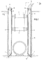
- FIG. 1 and 2 show views of a shoring device which is composed from supports 1, which are kept at a distance from spreaders 2 and in supports 1 vertically guided shoring plates 3, in which open channels 4 above and below are provided by the backfill material in the space below the shoring panels 3 can be filled.
- the lower mouths 6 of the channels 4 are through Sealing plates 7 closed so that no soil when driving in the shoring plates can penetrate into the channel 6.
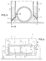
- FIG. 3 shows - this backfill under already installed pipe section and can be brought under the shoring plate.
- the backfill material can either be filled directly through channel 4 or - as the right shoring plate in Fig. 1 shows - through a filler pipe 13, which is arranged within the channel 4.
- a connecting piece 12 At the top opening 5 of the channel 4 or on the filler pipe 13 there is a connecting piece 12 with a coupling device, to which a filling hose 14 can be quickly coupled.
- a closure eye 7 is designed as an eyelet Projection 10 provided.
- the Closure plate 7 Before laying the pipe section, the Closure plate 7 by means of hammer blows or by means of one on the eyelet attaching pull rope the closure plate 7 from the closed position in a Open position shifted.
- Fig. 4 shows a guided in a sliding guide 8 closure plate 7, which in Open position is shifted.
- a stop 9 prevents the batten 7 can be pushed out of this sliding guide 8.
- Locking plate 7 With the help of the locking plate 7 attached to the projection 10 Locking plate 7 by hammer blows in the closed position or in the open position to be driven.
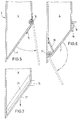
- closure plate 7 ' can also be opened on the Shoring plate 3 to be attached. 5 pivots Closure plate 7 'about a horizontal axis 15, which is at the top of the Closure plate 7 'is from the closed position to the open position. A formed as leg spring return spring 16 presses the closure plate 7 'in the closed position. Here, the closure plate 7 'lies on the walls of the shoring plate 3 on. By lifting the shoring plate 3 and filling in backfill material the closure plate 7 'opens automatically against the action of the return spring 16.
- Fig. 6 the closure plate 7 'is at its lower edge around a horizontal Axis 17 pivoted to the mounting plate 3.
- the closure plate 7 ' held in the closed position by a bolt 18.
- To open the in the Guide 19 led bolt 18 pulled up so that the locking plate 7 'around Axis 17 folds down, so that the filling material filled into channel 4 can emerge from the lower mouth of channel 4.
- the one in the canal room protruding part of the axis 17 and the non-pivoting part of the closure plate 7 ' are located under a deflector 20, which ensures that none Backfill material gets stuck on these parts.
- the closure plate 7 '' has a collar 21, the outer periphery of which Inner circumference of the channel mouth is adjusted. With this collar 21, the for Free end is tapered, the closure plate 7 '' in the Mouth of channel 4 can be inserted. By striking the projection 10 can this closure plate 7 '' can be removed from the channel mouth.
Landscapes
- Engineering & Computer Science (AREA)
- General Engineering & Computer Science (AREA)
- Mining & Mineral Resources (AREA)
- Mechanical Engineering (AREA)
- Civil Engineering (AREA)
- Structural Engineering (AREA)
- Life Sciences & Earth Sciences (AREA)
- General Life Sciences & Earth Sciences (AREA)
- Paleontology (AREA)
- Sewage (AREA)
- Excavating Of Shafts Or Tunnels (AREA)
- Revetment (AREA)
Abstract
Description
- Fig. 1
- eine Schnittansicht durch ein Verbauplattenpaar gemäß Schnittlinie I-I in Fig. 2,
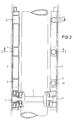
- Fig. 2
- eine Draufsicht und teilweise eine Schnittansicht nach der Schnittlinie II-II in Fig. 1,
- Fig. 3
- eine Schnittansicht entsprechend Fig. 1 beim Hochziehen der Verbauplatten und Verfüllen der Rohrbettung,
- Fig. 4
- eine Draufsicht auf eine in einer Schiebeführung geführten Verschlußplatte,
- Fig. 5
- eine Schnittansicht des unteren keilförmigen Endes einer Verbauplatte mit einer um eine obere Achse aufklappbaren Verschlußplatte,
- Fig. 6
- eine Schnittansicht des unteren keilförmigen Endes einer Verbauplatte mit einer um eine untere Achse aufklappbaren Verschlußplatte,
- Fig. 7
- eine Schnittansicht des unteren keilförmigen Endes einer Verbauplatte mit einer aufsteckbaren Verschlußplatte.
- 1
- Stütze
- 2
- Spreize
- 3
- Verbauplatte
- 4
- Kanal
- 5
- obere Öffnung
- 6
- untere Mündung
- 7
- verschiebbare Verschlußplatte
- 7'
- aufklappbare Verschlußplatte
- 7''
- aufsteckbare Verschlußplatte
- 8
- Schiebeführung
- 9
- Anschlag
- 10
- Vorsprung
- 11
- Abdeckplatte
- 12
- Anschlußstutzen
- 13
- Einfüllrohr
- 14
- Schlauch
- 15
- Schwenkachse
- 16
- Rückstellfeder
- 17
- Schwenkachse
- 18
- Riegel
- 19
- Riegelführung
- 20
- Abweiser
- 21
- Kragen
- 22
- untere Kante
Claims (19)
- Verfahren zum Einbau eines Kanalrohres, welches folgende Schritte umfaßt:a). Ausheben eines Grabens,b) Abstützen des Grabens mit einer Verbauvorrichtung, bestehend aus entlang den Längswandungen des Grabens verlaufenden Verbauplatten, die über Spreizmittel auf Abstand zueinander gehalten sind,c) Aufbringen eines Rohrabschnittes auf den Grabengrund undd) Rückbau der Verbauvorrichtung und Ausziehen der Verbauplatten, wobei gleichzeitig Verfüllmaterial zwischen die Längswandungen des Grabens und den Rohrabschnitt eingefüllt wird,
gekennzeichnet durch folgende Schritte:e) Auffüllen des Zwischenraumes zwischen der Längswandung des Grabens und der Außenwand des Rohrabschnittes während des Ausziehens der Verbauplatten durch Einfüllen von fließfähigem Verfüllmaterial in eine obere Mündung mindestens eines in den Verbauplatten von oben nach unten verlaufenden Kanals, der an der unten liegenden Längskante der Verbauplatten mündet. - Verfahren nach Anspruch 1, dadurch gekennzeichnet, daß der Graben mit solcher Breite ausgehoben wird, daß im wesentlichen kein Arbeitsraum zwischen der seitlichen Außenwand des in den Graben eingebrachten Rohrabschnittes und der Innenfläche der Verbauplatten frei bleibt.
- Verfahren nach Anspruch 1 oder 2, dadurch gekennzeichnet, daß als Verfüllmaterial in Schritt e) Beton verwendet wird.
- Verfahren nach einem der Ansprüche 1 oder 2, dadurch gekennzeichnet, daß als Verfüllmaterial in Schritt e) ein Bodenmörtel aus mit Wasser aufgeschlämmtem Erdreich und Zusätzen wie Kalk, Zement oder Bentonit verwendet wird.
- Verfahren nach einem der vorangehenden Ansprüche, dadurch gekennzeichnet, daß vor dem Einfüllen des Verfüllmaterials in den vertikalen Kanal der Verbauplatten eine Verschlußplatte von der unteren und gegebenenfalls oberen Mündung des Kanals entfernt wird.
- Verfahren nach einem der vorangehenden Ansprüche, dadurch gekennzeichnet, daß vor dem Einfüllen ein Schlauch für die Zuführung des Verfüllmaterials an einen Schlauchanschluß im Bereich der oberen Mündung des vertikalen Kanals angeschlossen wird.
- Grabenverbauvorrichtung, bestehend aus in Abständen längs und zu beiden Seiten eines Grabens senkrecht anzuordnenden Stützen (1), die Stützen (1) eines Stützenpaares auf Abstand haltenden Spreizen (2) und in seitlichen Führungen der Stützen (1) vertikal verschiebbar geführten Verbauplatten (3), wobei jede Verbauplatte (3) mindestens einen vom oberen Rand zum unteren Rand der Verbauplatte (3) führenden Kanal (4) aufweist, dadurch gekennzeichnet, daß die untere Mündung (6) des Kanals (4) durch eine leicht zu öffnende Verschlußplatte (7) verschließbar ist.
- Grabenverbauvorrichtung nach Anspruch 7, dadurch gekennzeichnet, daß am unteren Rand der Verbauplatte (3) eine Schiebeführung (8) angeordnet ist, welche zwei einander gegenüberliegende Ränder einer rechteckigen Verschlußplatte (7) umgreift.
- Grabenverbauvorrichtung nach Anspruch 8, dadurch gekennzeichnet, daß an den Enden der Schiebeführung (8) den Schiebeweg begrenzende Anschläge (9) angeordnet sind.
- Grabenverbauvorrichtung nach Anspruch 7, dadurch gekennzeichnet, daß die Verschlußplatte (7') um eine horizontale Achse (15,17) verschwenkbar an der Verbauplatte (3) befestigt ist.
- Grabenverbauvorrichtung nach Anspruch 10, dadurch gekennzeichnet, daß die Achse (15) am oberen Rand der Verschlußplatte (7') und in Nähe des oberen Randes der geneigten Fläche der keilförmigen Schneide der Verbauplatte (3) angeordnet ist.
- Grabenverbauvorrichtung nach Anspruch 11, gekennzeichnet durch eine die Verschlußplatte (7') in Schließstellung drückende Rückstellfeder (16).
- Grabenverbauvorrichtung nach Anspruch 10, dadurch gekennzeichnet, daß die Achse (17) am unteren Rand der Verschlußplatte (7') und in Nähe der unteren schneidenförmigen Kante der Verbauplatte (3) angeordnet ist.
- Grabenverbauvorrichtung nach Anspruch 13, gekennzeichnet durch einen die Verschlußplatte (7') in Schließstellung haltenden Riegel (17), der zum Öffnen der Verschlußplatte (7') verschiebbar ist.
- Grabenverbauvorrichtung nach Anspruch 7, dadurch gekennzeichnet, daß die Verschlußplatte (7'') einen Kragen (21) aufweist, dessen Form und Umfang dem Innenumfang der unteren Mündung des Kanals (4) angepaßt und in diese Mündung einsteckbar ist.
- Grabenverbauvorrichtung nach Anspruch 8 oder 15, dadurch gekennzeichnet, daß auf der Verschlußplatte (7) ein Vorsprung (10) zum Ansetzen eines Werkzeuges angeordnet ist.
- Grabenverbauvorrichtung nach Anspruch 16, dadurch gekennzeichnet, daß der auf der Verschlußplatte (7) befestigte Vorsprung eine Öse zum Befestigen eines Hakens oder eines Zugseils ist.
- Grabenverbauvorrichtung nach einem der Ansprüche 7 bis 17, dadurch gekennzeichnet, daß eine die obere Mündung (5) des Kanals (4) verschließende Abdeckplatte (11) leicht lösbar an der Verbauplatte (3) gehalten ist.
- Grabenverbauvorrichtung nach einem der Ansprüche 7 bis 18, dadurch gekennzeichnet, daß in der oberen Mündung (5) des Kanals (4) ein Anschlußstutzen (12) für die Schlauchkupplung eines Schlauchs (14) für die Zuführ von Verfüllmaterial angeordnet ist.
Applications Claiming Priority (2)
| Application Number | Priority Date | Filing Date | Title |
|---|---|---|---|
| DE19739920 | 1997-09-11 | ||
| DE19739920A DE19739920A1 (de) | 1997-09-11 | 1997-09-11 | Verfahren und Verbauvorrichtung für den Rohreinbau |
Publications (3)
| Publication Number | Publication Date |
|---|---|
| EP0902129A2 true EP0902129A2 (de) | 1999-03-17 |
| EP0902129A3 EP0902129A3 (de) | 1999-11-17 |
| EP0902129B1 EP0902129B1 (de) | 2002-11-27 |
Family
ID=7842003
Family Applications (1)
| Application Number | Title | Priority Date | Filing Date |
|---|---|---|---|
| EP98116582A Expired - Lifetime EP0902129B1 (de) | 1997-09-11 | 1998-09-02 | Verfahren und Vorrichtung für den Rohreinbau |
Country Status (3)
| Country | Link |
|---|---|
| EP (1) | EP0902129B1 (de) |
| DE (2) | DE19739920A1 (de) |
| ES (1) | ES2186957T3 (de) |
Cited By (4)
| Publication number | Priority date | Publication date | Assignee | Title |
|---|---|---|---|---|
| WO2013056306A1 (en) * | 2011-10-19 | 2013-04-25 | Quickway Constructions Pty Ltd | Shoring box system and method |
| CN113802579A (zh) * | 2021-11-03 | 2021-12-17 | 中建八局(厦门)建设有限公司 | 一种市政管网沟槽开挖用支撑防护装置 |
| CN116378063A (zh) * | 2023-05-31 | 2023-07-04 | 浏阳市山田建筑工程有限公司 | 一种市政管道工程用沟槽施工方法 |
| CN121654112A (zh) * | 2026-02-09 | 2026-03-13 | 陕西理工大学 | 一种具有支撑功能的土木工程施工辅助设备 |
Families Citing this family (4)
| Publication number | Priority date | Publication date | Assignee | Title |
|---|---|---|---|---|
| DE10124069C1 (de) * | 2001-05-16 | 2002-10-24 | Logic Logistic Consult Ingenie | Grabenverbau für Rohr- und Medienleitungen |
| DE102006013410B4 (de) * | 2005-03-18 | 2007-08-16 | Logic-Logistic Consult Ingenieurgesellschaft Mbh | Vorrichtung zur Verlegung von Rohrleitungen in Gräben |
| DE102006018581B3 (de) * | 2006-04-21 | 2007-07-26 | Prof. Dr.-Ing. Stein & Partner Gmbh | Verfahren und Vorrichtung zur hängenden Verlegung von Leitungen |
| DE202017101470U1 (de) | 2017-03-14 | 2017-04-27 | Sbh Tiefbautechnik Gmbh | Grabenverbau zum Verbau von Rohrleitungsgräben |
Family Cites Families (6)
| Publication number | Priority date | Publication date | Assignee | Title |
|---|---|---|---|---|
| JPS4946968B1 (de) * | 1971-05-25 | 1974-12-13 | ||
| DE2344855A1 (de) * | 1973-09-06 | 1975-03-27 | Tiefbauunternehmung Gebr Echte | Einrichtung zum abfangen des wandseitigen erdreiches in graeben, baugruben od. dgl. |
| IT1246082B (it) * | 1990-01-16 | 1994-11-14 | Roberto Visconti | Cassaforma tubolare per la realizzazione di pali di fondazione in calcestruzzo |
| DE4028832A1 (de) * | 1990-09-11 | 1992-03-12 | Wilhelm Hess | Verfahren und vorrichtung zum verbau tiefer graeben |
| DE4137541C2 (de) * | 1991-11-14 | 1999-09-16 | Keller Grundbau Gmbh | Arbeitsgerät zur Herstellung von Ortbetonpfählen |
| DE4322336C2 (de) * | 1993-07-05 | 1996-12-19 | Emunds & Staudinger Gmbh & Co | Verbauvorrichtung |
-
1997
- 1997-09-11 DE DE19739920A patent/DE19739920A1/de not_active Withdrawn
-
1998
- 1998-09-02 DE DE59806419T patent/DE59806419D1/de not_active Expired - Lifetime
- 1998-09-02 ES ES98116582T patent/ES2186957T3/es not_active Expired - Lifetime
- 1998-09-02 EP EP98116582A patent/EP0902129B1/de not_active Expired - Lifetime
Non-Patent Citations (1)
| Title |
|---|
| None |
Cited By (6)
| Publication number | Priority date | Publication date | Assignee | Title |
|---|---|---|---|---|
| WO2013056306A1 (en) * | 2011-10-19 | 2013-04-25 | Quickway Constructions Pty Ltd | Shoring box system and method |
| GB2511229A (en) * | 2011-10-19 | 2014-08-27 | Paul Breen | Shoring box system and method |
| GB2511229B (en) * | 2011-10-19 | 2017-10-11 | Breen Paul | Shoring box system and method of using the same |
| CN113802579A (zh) * | 2021-11-03 | 2021-12-17 | 中建八局(厦门)建设有限公司 | 一种市政管网沟槽开挖用支撑防护装置 |
| CN116378063A (zh) * | 2023-05-31 | 2023-07-04 | 浏阳市山田建筑工程有限公司 | 一种市政管道工程用沟槽施工方法 |
| CN121654112A (zh) * | 2026-02-09 | 2026-03-13 | 陕西理工大学 | 一种具有支撑功能的土木工程施工辅助设备 |
Also Published As
| Publication number | Publication date |
|---|---|
| DE19739920A1 (de) | 1999-03-18 |
| EP0902129B1 (de) | 2002-11-27 |
| ES2186957T3 (es) | 2003-05-16 |
| EP0902129A3 (de) | 1999-11-17 |
| DE59806419D1 (de) | 2003-01-09 |
Similar Documents
| Publication | Publication Date | Title |
|---|---|---|
| DE112012004108T5 (de) | Verbaukasten-system und -verfahren | |
| DE10158524A1 (de) | Pfahlvorrichtung und Verfahren zur Konstruktion von Betonpfählen in weichem Erdboden | |
| DE69000562T2 (de) | Verfahren und vorrichtung zum abloesen einer am beton haftenden dichtung eines im boden gegossenen wandabschnittes. | |
| CH623374A5 (de) | ||
| DE2944385A1 (de) | Verfahren zum herstellen von schlitzwaenden | |
| EP3662116A1 (de) | Verfahren zum herstellen eines deckenelements und deckenschalung | |
| EP0902129B1 (de) | Verfahren und Vorrichtung für den Rohreinbau | |
| EP2921599A1 (de) | Vorrichtung zum verbinden von elementen, element zum aufbau eines kanals und verfahren zur verlegung von elementen | |
| EP1020568A1 (de) | Vorrichtung zum provisorischen Abdecken eines Kontrollschachtes | |
| DE102012101366B3 (de) | Unterflur-Schacht, Bausatz zum Herstellen und Verfahren zum Einbau dafür | |
| DE202019100752U1 (de) | Verbauvorrichtung | |
| DE7816839U1 (de) | Gelenkige vorrichtung zum aussteifen der waende von baugraeben, rohrgraeben u.dgl. | |
| CH666502A5 (de) | Verfahren zum herstellen einer betonwand in der schlitzbauweise, anordnung zur durchfuehrung des verfahrens und nach dem verfahren hergestellte betonwand. | |
| DE2057263A1 (de) | Vorrichtung zum Abstuetzen von Grabenwaenden | |
| DE19901556A1 (de) | Vorrichtung und Verfahren zum Entfernen von Überbeton im Bereich einer Schlitzwandfuge | |
| DE10124069C1 (de) | Grabenverbau für Rohr- und Medienleitungen | |
| DE29724414U1 (de) | Grabenverbauvorrichtung | |
| DE1784739A1 (de) | Verfahren und Vorrichtung zur Herstellung von Schaechten,Revisionskammern und Roehrenverbindungen | |
| DE102016118132B4 (de) | Vorrichtung und Verfahren zum Einbauen eines Rohrs in den Untergrund eines Gewässers | |
| EP0811723B1 (de) | Stütze für Grabenverbauvorrichtungen | |
| DE19803074A1 (de) | Schacht und Verfahren zum Erstellen eines solchen | |
| DE69107696T2 (de) | yinrichtung zum Erleichtern des Herausziehens einer Schalung, und Verwendung zum Herstellen einer Bodenschlitzwand. | |
| DE3626462C2 (de) | ||
| DE4236489C2 (de) | Verfahren zum Einbau von Dichtwandfolien in eine Dichtungsschlitzwand und Einrichtung zur Durchführung des Verfahrens | |
| DE3432706A1 (de) | Verfahren zum nachtraeglichen einbringen einer zusaetzlichen abdichtung in schlitzwaenden und vorrichtung zur durchfuehrung des verfahrens |
Legal Events
| Date | Code | Title | Description |
|---|---|---|---|
| PUAI | Public reference made under article 153(3) epc to a published international application that has entered the european phase |
Free format text: ORIGINAL CODE: 0009012 |
|
| AK | Designated contracting states |
Kind code of ref document: A2 Designated state(s): DE ES FR GB |
|
| AX | Request for extension of the european patent |
Free format text: AL;LT;LV;MK;RO;SI |
|
| PUAL | Search report despatched |
Free format text: ORIGINAL CODE: 0009013 |
|
| AK | Designated contracting states |
Kind code of ref document: A3 Designated state(s): AT BE CH CY DE DK ES FI FR GB GR IE IT LI LU MC NL PT SE |
|
| AX | Request for extension of the european patent |
Free format text: AL;LT;LV;MK;RO;SI |
|
| 17P | Request for examination filed |
Effective date: 20000317 |
|
| AKX | Designation fees paid |
Free format text: DE ES FR GB |
|
| 17Q | First examination report despatched |
Effective date: 20010308 |
|
| GRAG | Despatch of communication of intention to grant |
Free format text: ORIGINAL CODE: EPIDOS AGRA |
|
| GRAG | Despatch of communication of intention to grant |
Free format text: ORIGINAL CODE: EPIDOS AGRA |
|
| GRAH | Despatch of communication of intention to grant a patent |
Free format text: ORIGINAL CODE: EPIDOS IGRA |
|
| GRAH | Despatch of communication of intention to grant a patent |
Free format text: ORIGINAL CODE: EPIDOS IGRA |
|
| GRAA | (expected) grant |
Free format text: ORIGINAL CODE: 0009210 |
|
| AK | Designated contracting states |
Kind code of ref document: B1 Designated state(s): DE ES FR GB |
|
| REG | Reference to a national code |
Ref country code: GB Ref legal event code: FG4D Free format text: NOT ENGLISH |
|
| REF | Corresponds to: |
Ref document number: 59806419 Country of ref document: DE Date of ref document: 20030109 |
|
| ET | Fr: translation filed | ||
| GBT | Gb: translation of ep patent filed (gb section 77(6)(a)/1977) |
Effective date: 20030331 |
|
| REG | Reference to a national code |
Ref country code: ES Ref legal event code: FG2A Ref document number: 2186957 Country of ref document: ES Kind code of ref document: T3 |
|
| PLBE | No opposition filed within time limit |
Free format text: ORIGINAL CODE: 0009261 |
|
| STAA | Information on the status of an ep patent application or granted ep patent |
Free format text: STATUS: NO OPPOSITION FILED WITHIN TIME LIMIT |
|
| 26N | No opposition filed |
Effective date: 20030828 |
|
| PGFP | Annual fee paid to national office [announced via postgrant information from national office to epo] |
Ref country code: DE Payment date: 20101129 Year of fee payment: 13 |
|
| PGFP | Annual fee paid to national office [announced via postgrant information from national office to epo] |
Ref country code: GB Payment date: 20110923 Year of fee payment: 14 Ref country code: ES Payment date: 20110923 Year of fee payment: 14 Ref country code: FR Payment date: 20111005 Year of fee payment: 14 |
|
| GBPC | Gb: european patent ceased through non-payment of renewal fee |
Effective date: 20120902 |
|
| REG | Reference to a national code |
Ref country code: FR Ref legal event code: ST Effective date: 20130531 |
|
| PG25 | Lapsed in a contracting state [announced via postgrant information from national office to epo] |
Ref country code: DE Free format text: LAPSE BECAUSE OF NON-PAYMENT OF DUE FEES Effective date: 20130403 Ref country code: GB Free format text: LAPSE BECAUSE OF NON-PAYMENT OF DUE FEES Effective date: 20120902 |
|
| REG | Reference to a national code |
Ref country code: DE Ref legal event code: R119 Ref document number: 59806419 Country of ref document: DE Effective date: 20130403 |
|
| PG25 | Lapsed in a contracting state [announced via postgrant information from national office to epo] |
Ref country code: FR Free format text: LAPSE BECAUSE OF NON-PAYMENT OF DUE FEES Effective date: 20121001 |
|
| REG | Reference to a national code |
Ref country code: ES Ref legal event code: FD2A Effective date: 20131022 |
|
| PG25 | Lapsed in a contracting state [announced via postgrant information from national office to epo] |
Ref country code: ES Free format text: LAPSE BECAUSE OF NON-PAYMENT OF DUE FEES Effective date: 20120903 |