EP0901038A2 - Tragbarer Projektonsschirm - Google Patents
Tragbarer Projektonsschirm Download PDFInfo
- Publication number
- EP0901038A2 EP0901038A2 EP98116277A EP98116277A EP0901038A2 EP 0901038 A2 EP0901038 A2 EP 0901038A2 EP 98116277 A EP98116277 A EP 98116277A EP 98116277 A EP98116277 A EP 98116277A EP 0901038 A2 EP0901038 A2 EP 0901038A2
- Authority
- EP
- European Patent Office
- Prior art keywords
- frames
- screen assembly
- portable screen
- walls
- extender
- Prior art date
- Legal status (The legal status is an assumption and is not a legal conclusion. Google has not performed a legal analysis and makes no representation as to the accuracy of the status listed.)
- Granted
Links
Images


Classifications
-
- G—PHYSICS
- G03—PHOTOGRAPHY; CINEMATOGRAPHY; ANALOGOUS TECHNIQUES USING WAVES OTHER THAN OPTICAL WAVES; ELECTROGRAPHY; HOLOGRAPHY
- G03B—APPARATUS OR ARRANGEMENTS FOR TAKING PHOTOGRAPHS OR FOR PROJECTING OR VIEWING THEM; APPARATUS OR ARRANGEMENTS EMPLOYING ANALOGOUS TECHNIQUES USING WAVES OTHER THAN OPTICAL WAVES; ACCESSORIES THEREFOR
- G03B21/00—Projectors or projection-type viewers; Accessories therefor
- G03B21/54—Accessories
- G03B21/56—Projection screens
-
- G—PHYSICS
- G09—EDUCATION; CRYPTOGRAPHY; DISPLAY; ADVERTISING; SEALS
- G09F—DISPLAYING; ADVERTISING; SIGNS; LABELS OR NAME-PLATES; SEALS
- G09F19/00—Advertising or display means not otherwise provided for
- G09F19/12—Advertising or display means not otherwise provided for using special optical effects
- G09F19/18—Advertising or display means not otherwise provided for using special optical effects involving the use of optical projection means, e.g. projection of images on clouds
-
- G—PHYSICS
- G03—PHOTOGRAPHY; CINEMATOGRAPHY; ANALOGOUS TECHNIQUES USING WAVES OTHER THAN OPTICAL WAVES; ELECTROGRAPHY; HOLOGRAPHY
- G03B—APPARATUS OR ARRANGEMENTS FOR TAKING PHOTOGRAPHS OR FOR PROJECTING OR VIEWING THEM; APPARATUS OR ARRANGEMENTS EMPLOYING ANALOGOUS TECHNIQUES USING WAVES OTHER THAN OPTICAL WAVES; ACCESSORIES THEREFOR
- G03B21/00—Projectors or projection-type viewers; Accessories therefor
- G03B21/54—Accessories
- G03B21/56—Projection screens
- G03B21/58—Projection screens collapsible, e.g. foldable; of variable area
Definitions
- the present invention relates generally to a screen for displaying, on an enlarged scale, an image projected by a projector or a projection TV set and in particular but not exclusively to a portable screen assembly that is easy to carry and can be installed at an optional location such as, for example, on a floor, a table or the like.
- An image projected by a projector or, in some cases, a projection TV set is generally displayed, on an enlarged scale, on a reflection type screen or a transmission type screen.
- Portable screen assemblies are today available in which a screen is wound around a roll housed in a housing.
- the housing is initially installed at a desired place, and the screen is subsequently extended by, for example, an extension means somewhat similar to a pantograph by the action of the biasing force of a spring mounted therein.
- the present invention has been developed in view of such a demand.
- the portable screen assembly includes first and second frames extending parallel to each other, a spring-biased roll rotatably mounted in the first frame, a screen bonded at one end thereof to the second frame and wound around the spring-biased roll, an extender for biasing the first and second frames away from each other to impart a predetermined tension to the screen, and a plurality of support legs for supporting the first and second frames generally vertically during use.
- This construction is simple, facilitates carrying and handling of the portable screen assembly, and reduces the manufacturing cost thereof.
- the extender includes an elastic member having an elastic force, which is determined appropriately relative to an elastic force of a spring mounted in the spring-biased roll so that the first and second frames can be retained at a desired interval.
- the width of the screen can be adjusted according to the distance between the screen and a projector.
- the extender includes a first pair of rails extending parallel to each other and a second pair of rails extending parallel to each other, with the first pair of rails hingedly connected to the second pair of rails.
- the extender includes a pair of rails hingedly connected to each other at first ends thereof and also hingedly connected to the first and second frames, respectively, at second ends thereof.
- the first and second frames are used as casings for accommodating and protecting the spring-biased roll, the screen, and the extender when the portable screen assembly is not in use.
- the two frames service both as the supporting members for supporting the screen and the casings for protecting internal component parts and, hence, the portable screen assembly can be made compact and inexpensive.
- each of the plurality of support legs includes a plurality of first walls formed thereon and having respective projections formed therewith, while each of the first and second frames includes a plurality of second walls formed thereon.
- the support legs are retained as extended by causing the first walls to abut against the second walls, respectively, while the support legs are folded by releasing abutment of the first walls against the second walls. Because a force applied to each support leg can be dispersed by virtue of engagement between the plurality of first walls and the plurality of second walls, even a soft and fragile material such as, for example, a resin can withstand a relatively large force, reducing the manufacturing cost of the support legs.
- each of the projections has a first inclined surface formed on one side thereof, wherein a lead-in force of each support leg onto an associated one of the first and second frames is generated during folding of the support leg by causing the first inclined surface to abut against an edge of an associated one of the second walls.
- This construction requires no additional leg locking means to lock the support legs at their rest positions, making it possible to simplify the construction of the support legs and to manufacture the support legs at a low cost.
- each of the projections has a second inclined surface formed on the other side thereof, wherein the second inclined surface is in abutment with the edge of the associated one of the second walls when each support leg has been extended, preventing an external force from damaging the support leg.
- the first and second inclined surfaces extend so as to cross each other.
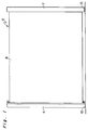
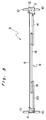
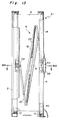
- Figs. 1 to 3 depict a portable screen assembly S according to a first embodiment of the present invention, shown as extended during use thereof.
- the portable screen assembly S includes two frames 2, 4 made of, for example, aluminum and extending parallel to each other, a screen 6 extended between the two frames 2, 4, an extender or extension means 8 for biasing the frames 2, 4 away from each other so as to maintain them at a desired interval, and a plurality of support legs 10 hingedly connected to lower ends of the frames 2, 4 to hold the frames 2, 4 generally vertically.
- the frame 2 accommodates a spring-biased roll 12 rotatably mounted therein around which the screen 6 is wound.
- the screen 6 has one side edge bonded to the spring-biased roll 12 and the other side edge bonded to an angled member (described later) secured to an inner surface of the frame 4.
- the screen 6 is a known one that has a base fabric made of, for example, glass or PET, a reflective layer bonded to the base fabric, a bead layer or a polarization layer formed on the reflective layer, and a resin layer covered on the bead or polarization layer.
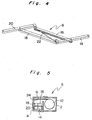
- the extender 8 includes a pair of rails 14, 20 extending parallel to each other and another pair of rails 16, 18 extending parallel to each other.
- Each of the rails 14, 16, 18, 20 has a generally U-shaped cross section.
- These rails 14, 16, 18, 20 are hereinafter referred to as first, second, third and fourth rails, respectively.
- the first rail 14 has one end hingedly connected to an intermediate portion 2a of the frame 2, an intermediate portion hingedly connected to one end of the second rail 16, and the other end hingedly connected to one end of the third rail 18.
- the other end of the second rail 16 and that of the third rail 18 are hingedly connected to one end and an intermediate portion of the fourth rail 20, respectively, while the other end of the fourth rail 20 is hingedly connected to an intermediate portion 4a of the frame 4.
- the two frames 2, 4 are biased away from each other by an elastic member 22 such as, for example, a coil spring that has one end connected to a hinged portion between the first and third rails 14, 18 and the other end connected to a hinged portion between the second and fourth rails 16, 20.
- Figs. 5 to 7 depict the portable screen assembly S when the two frames 2, 4 are mated to each other after the use of the portable screen assembly S.
- the two frames 2, 4 act as casings for protecting the internal component parts such as the spring-biased roll 12, the screen 6 completely wound therearound and the like.
- the plurality of support legs 10 are hingedly connected to four corners of the bottom surfaces of the frames 2, 4, rotation of the support legs 10 results in storage thereof on the bottom surfaces of the frames 2, 4, preventing the support legs 10 from protruding laterally from the frames 2, 4 (Fig. 7).
- reference numeral 24 denotes an angled member which is secured to an inner surface of the frame 4 and to which one end of the screen 6 is bonded.
- the portable screen assembly S of the above-described construction operates as follows.
- the two frames 2, 4 are mated to each other so that opposing surfaces thereof are held in contact with each other.
- the whole portable screen assembly S takes the form of a generally rectangular parallelopiped and, hence, it is very easy to carry and store.
- the screen 6 is completely wound around the spring-biased roll 12 by the biasing force of a spring (not shown) mounted in the spring-biased roll 12, while the extender 8 comprised of the four rails 14, 16, 18, 20 is completely folded so as to extend parallel to the spring-biased roll 12, as shown in Figs. 5 and 6.
- the plurality of support legs 10, which support the frames 2, 4 during use of the portable screen assembly S, are held on the bottom surfaces of the frames 2, 4 so as not to protrude from the side surfaces of the frames 2, 4, as shown in Fig. 7. Accordingly, storage and carrying of the screen body is not hindered.
- the support legs 10 are first rotated so as to protrude from the side surfaces of the frames 2, 4 until the support legs 10 become generally perpendicular to the screen surface.
- the frames 2, 4 are positively supported by the support legs 10 and extend generally perpendicular to the surface on which the portable screen assembly S is installed (Fig. 3).
- the screen 6 is drawn out of the spring-biased roll 12 against the biasing force of the spring mounted in the spring-biased roll 12, and a predetermined tension is imparted to the screen 6 by the extender 8, as shown in Figs. 1 to 3.
- the biasing force of the elastic member 22 of the extender 8 is determined in consideration of the spring force of the spring-biased roll 12 and, hence, the interval between the frames 2, 4 can be appropriately set according to the distance between the screen 6 and a projector.
- the extender 8 comprised of the four rails 14, 16, 18, 20 is folded and the screen 6 is wound around the spring-biased roll 12 simply by pushing one of the frames 2, 4 relative to the other. Closure of the portable screen assembly S is completed by rotating all the support legs 10 to respective positions as shown in Fig. 7.
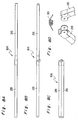
- Figs. 8A to 8D depict a modification 8A of the extender.
- Figs. 8A and 8B depict the condition in which the extender 8A has been completely extended, while Fig. 8C depicts the condition in which the extender 8 has been completely folded.
- the extender 8A includes a pair of rails 26, 28 having a generally U-shaped cross section.
- the first rail 26 has one end hingedly connected to the intermediate portion 2a of the frame 2 and the other end hingedly connected to one end of the second rail 28 via a pin (not shown).
- the other end of the second rail 28 is hingedly connected to the intermediate portion 4a of the frame 4.
- an elastic member 30 such as, for example, a coil spring is mounted on a hinged portion between the first and second rails 26, 28 so as to bias the first and second rails 26, 28 in a direction in which they extend generally straight, as shown in Figs. 8A and 8B.
- the extender 8 shown in Fig. 4 and the extender 8A shown in Figs. 8A to 8D differ only in the number of the rails and in the shape of the elastic member and are substantially identical in operation, explanation of the operation of the extender 8A is omitted.
- the portable screen assembly S may have a locking means for locking the two frames 2, 4 so that they may not be separated from each other during storage or carrying of the portable screen assembly S.
- one of the frames 2, 4 has a handle secured thereto with which the portable screen assembly S can be readily carried.
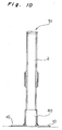
- Figs. 9 to 12 depict a portable screen assembly S1 according to a second embodiment of the present invention.
- Figs. 9 and 10 depict the portable screen assembly S1 when it is in use
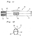
- Figs. 11 and 12 depict the portable screen assembly S1 when it is stored or not in use.
- This portable screen assembly S1 has locking means 32 for locking the two frames 2, 4 that function as casings when they are closed.
- the portable screen assembly S1 also has a handle 34 secured to one of the frames 2, 4 for use in carrying the portable screen assembly S1.
- the portable screen assembly S1 differs from the portable screen assembly S according to the first embodiment of the present invention discussed above in that the plurality of support legs 10 for holding the frames 2, 4 generally vertically during use of the portable screen assembly S1 are stored on the side surfaces of the frames 2, 4.
- the component parts such as the screen 6 to be extended between the frames 2, 4, the extender 8 for biasing the frames 2, 4 away from each other, the spring-biased roll 12 around which the screen 6 is wound and the like are generally identical to those mounted in the portable screen assembly S according to the first embodiment of the present invention. Accordingly, explanation of such component parts is omitted and only the differences are discussed hereinafter.
- each of the frames or casings 2, 4 has two grips 36 or 38 mounted on side surfaces thereof at intermediate portions in a direction longitudinally thereof.
- the grips 36 mounted on the frame 2 have respective locking means 32 mounted thereon.
- Each of the locking means 32 has a hook 32a formed therewith at a distal end thereof, while each of the grips 38 mounted on the frame 4 has a projection 38a formed therewith at a distal end thereof. Locking or release of the locking is achieved by the operation of the locking means 32, i.e, by engaging the hook 32a with the corresponding projection 38a of the grip 38 or by disengaging the former from the latter.
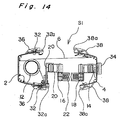
- the frames 2, 4 have respective leg mounts 40 screwed down to lower portions thereof, and a plurality of, for example two, support legs 10 are hingedly connected to each of the leg mounts 40.
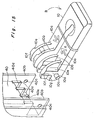
- Each support leg 10 is generally in the form of "U” and is molded from, for example, a resinous material.
- Each support leg 10 has two support branches 10a that are connected to each other at a distal end thereof but separated at a proximal end thereof.
- Each support branch 10a has a plurality of (two in the figure) walls 10b integrally formed therewith so as to extend upwardly therefrom in parallel to one another, and also has a pin 10c integrally formed therewith so as to protrude laterally therefrom (in a direction perpendicular thereto).
- Each of the walls 10b has a projection 10d integrally formed therewith so as to extend outwardly therefrom.
- the projection 10d has an inclined front surface 10e facing to the distal end of the support leg 10 and a non-inclined rear surface 10f facing to the proximal end of the support leg 10.
- Another inclined surface 10g is formed on each wall 10b so as to cross the non-inclined rear surface 10f of the projection 10d.
- the inclined surface 10g extends in a direction generally perpendicular to the inclined front surface 10e of the projection 10d.
- each of the leg mounts 40 has a plurality of, for example four, downwardly extending walls 40a integrally formed therewith at a location corresponding to each support leg 10.
- Each of the leg mounts 40 also has two ribs 40b integrally formed therewith on respective sides of the plurality of downwardly extending walls 40a.
- the plurality of downwardly extending walls 40a and the two ribs 40b extend parallel to one another.
- the two ribs 40b have respective pin insertion holes 40c defined therein to receive the pins 10c formed on the support leg 10.
- outer two walls 10b of the support leg 10 are first inserted into outer spaces of a plurality of spaces defined between the downwardly extending walls 40a of the leg mount 40, while inner two walls 10b of the support leg 10 are simultaneously inserted into a central space defined between inner two downwardly extending walls 40a of the leg mount 40. Subsequently pressing the two support branches 10a inwardly as shown by arrows A allows the pins 10c to be inserted into the corresponding pin insertion holes 40c formed in the ribs 40b of the leg mount 40.
- each support leg 10 is folded down and stored between the two ribs 40b so as to be held in contact with the side surface of the leg mount 40.
- the inclined front surfaces 10e of the projections 10d abut against associated side edges 40d of bottom surfaces of the downwardly extending walls 40a, generating a lead-in force of the support leg 10. This lead-in force acts to retain the support leg 10 as folded.
- each support leg 10 When the portable screen assembly S1 is used, each support leg 10 is first rotated or unfolded In a direction shown by an arrow B against the lead-in force, thereby pressing the inclined front surfaces 10e of the projections 10d against the side edges 40d of the downwardly extending walls 40a and moving the inclined front surfaces 10e relative to the side edges 40d.
- the support branches 10a receive a compressive force in the directions shown by the arrows A, which compressive force in turn makes the support branches 10a approach each other.
- the non-inclined rear surfaces 10f of the projections 10d are in abutment with associated front surfaces 40e of the downwardly extending walls 40a, while the inclined surfaces 10g crossing the non-inclined rear surfaces 10f at right angles are in abutment with the side edges 40d of the downwardly extending walls 40a, thus locking the support leg 10 in the 90°-extended condition to positively hold the frame 2, 4.
- the support legs 10 are of a failure-proof construction. That is, when the portable screen assembly S1 is being carried without folding some or all of the support legs 10, the support legs 10 are not subject to damage even if an external force is suddenly applied thereto.
- each of the frames 2, 4 is provided with two support legs 10, two rotational axes (the pins 10c) of the latter do not lie on the same straight line but cross each other at a certain angle so that the distal ends of the two support legs 10 open outwardly. Because of this, if the 90°-extended support leg 10 is caused to accidentally impinge against an object or the surface on which the portable screen assembly S1 is installed during movement or installation thereof, there is a possibility that a relatively large force may be obliquely applied to the support leg 10. Such a force, however, presses the support branches 10a inwardly and, hence, the support leg 10 is folded, avoiding damage thereof.
- the support leg 10 has the following advantages.
- Fig. 16 depicts a modified form of the support leg 10 and the leg mount 40 shown in Fig. 15.
- inner two walls 40a have respective front surfaces 40e inclined or tapered outwardly, while inner two walls 10b of the support leg 10 have respective Inclined or tapered rear surfaces 10f complementary to the associated front surfaces 40e of the downwardly extending walls 40a.
Applications Claiming Priority (6)
| Application Number | Priority Date | Filing Date | Title |
|---|---|---|---|
| JP24089397 | 1997-09-05 | ||
| JP24089397 | 1997-09-05 | ||
| JP240893/97 | 1997-09-05 | ||
| JP4563098 | 1998-02-26 | ||
| JP04563098A JP3385207B2 (ja) | 1997-09-05 | 1998-02-26 | 可搬式スクリーン |
| JP45630/98 | 1998-02-26 |
Publications (3)
| Publication Number | Publication Date |
|---|---|
| EP0901038A2 true EP0901038A2 (de) | 1999-03-10 |
| EP0901038A3 EP0901038A3 (de) | 2002-05-22 |
| EP0901038B1 EP0901038B1 (de) | 2003-12-10 |
Family
ID=26385657
Family Applications (1)
| Application Number | Title | Priority Date | Filing Date |
|---|---|---|---|
| EP98116277A Expired - Lifetime EP0901038B1 (de) | 1997-09-05 | 1998-08-28 | Tragbarer Projektonsschirm |
Country Status (7)
| Country | Link |
|---|---|
| US (1) | US6249377B1 (de) |
| EP (1) | EP0901038B1 (de) |
| JP (1) | JP3385207B2 (de) |
| KR (1) | KR100366319B1 (de) |
| CA (1) | CA2245983C (de) |
| DE (1) | DE69820365T2 (de) |
| TW (1) | TW446850B (de) |
Cited By (9)
| Publication number | Priority date | Publication date | Assignee | Title |
|---|---|---|---|---|
| WO2004055590A3 (en) * | 2002-12-18 | 2004-09-10 | Vizoo Invest Aps | A method and an arrangement for projecting images and a projection screen arrangement |
| WO2005013244A2 (en) * | 2003-08-04 | 2005-02-10 | Allen Meyer | Retractable display apparatus |
| DE102004002620A1 (de) * | 2004-01-16 | 2005-08-18 | Felix Schram | Anordnung mit wenigstens einem aufrollbaren Trenn- bzw. Wandelement |
| WO2006019813A2 (en) * | 2004-07-28 | 2006-02-23 | Hewlett-Packard Development Company, L.P. | Projection screen with means for selectively supporting or locking the screen |
| WO2006074698A1 (de) | 2005-01-17 | 2006-07-20 | Felix Schram | Anordnung mit wenigstens einem auftrollbaren trenn- bzw. wandelement |
| EP1789844A1 (de) * | 2004-09-17 | 2007-05-30 | Paul Clubbe | Schirm-baugruppe |
| EP1990681A2 (de) * | 2007-05-09 | 2008-11-12 | Bright Supply Corporation | Einziehbarer Rahmen eines Projektionsschirms |
| EP2273313A1 (de) * | 2008-05-02 | 2011-01-12 | Izumi-Cosmo Company, Limited | Tragbare bildschirmvorrichtung |
| WO2011054694A1 (de) | 2009-10-26 | 2011-05-12 | Basf Se | Verfahren zum recycling von mit biologisch abbaubaren polymeren geleimten und/oder beschichteten papierprodukten |
Families Citing this family (48)
| Publication number | Priority date | Publication date | Assignee | Title |
|---|---|---|---|---|
| US6873460B1 (en) * | 1999-07-09 | 2005-03-29 | Sarnoff Corporation | Retractable rear projection display |
| JP4141864B2 (ja) * | 2002-05-23 | 2008-08-27 | 株式会社オーエス | 自立式手動昇降スクリーン |
| KR200298928Y1 (ko) | 2002-09-18 | 2002-12-31 | 최해용 | 벽걸이용 스크린 |
| US6785047B1 (en) | 2002-12-20 | 2004-08-31 | Draper, Inc. | Tensioned projection screen apparatus |
| US7369310B1 (en) | 2004-08-31 | 2008-05-06 | Draper, Inc. | Tensioned projection screen |
| US7316257B2 (en) | 2003-03-25 | 2008-01-08 | Cameron Ronald A | Portable screen assembly |
| EP1642253B1 (de) * | 2003-06-23 | 2012-10-03 | Simon Richard Daniel | Anzeigevorrichtung mit ausziehbahrem schirm |
| US7314079B2 (en) * | 2003-09-09 | 2008-01-01 | Asmo Co., Ltd. | Sunshade system having blind sheet |
| TWI318328B (en) | 2003-10-31 | 2009-12-11 | Izumi Cosmo Co Ltd | A removable screen device |
| KR200348134Y1 (ko) * | 2004-02-05 | 2004-05-03 | 노주석 | 휴대용 스크린 장치 |
| JP2005249828A (ja) * | 2004-03-01 | 2005-09-15 | Matsushita Electric Ind Co Ltd | 表示装置 |
| US7080420B2 (en) * | 2004-09-16 | 2006-07-25 | Scott Damron | Adjustable head-support for therapy tables |
| JP2006317796A (ja) * | 2005-05-13 | 2006-11-24 | Sony Corp | スクリーン装置および画像表示システム |
| US7619814B2 (en) * | 2006-02-14 | 2009-11-17 | Seiko Epson Corporation | Portable projection screen assembly |
| US7612938B2 (en) * | 2006-02-14 | 2009-11-03 | Seiko Epson Corporation | Portable projection screen assembly |
| US7623290B2 (en) * | 2006-02-14 | 2009-11-24 | Seiko Epson Corporation | Portable screen assemblies for projectors |
| US7936505B2 (en) * | 2006-08-28 | 2011-05-03 | Draper, Inc. | Tensioned projection screen |
| US20080158669A1 (en) * | 2006-12-29 | 2008-07-03 | 3M Innovative Properties Company | Projection screen apparatus for use with portable digital projectors |
| JP2009069288A (ja) | 2007-09-11 | 2009-04-02 | Seiko Epson Corp | スクリーン |
| TW200919075A (en) * | 2007-10-19 | 2009-05-01 | Bright View Technologies Inc | Portable front projection screen assemblies with flexible screens |
| US8365798B2 (en) * | 2008-05-27 | 2013-02-05 | Steelcase Inc. | Privacy screen assembly |
| JP2010019953A (ja) * | 2008-07-09 | 2010-01-28 | Seiko Epson Corp | スクリーン |
| EP2440973A4 (de) | 2009-06-12 | 2013-07-31 | Draper Inc | Gespannte projektionsbildschirmanordnung |
| JP2012053378A (ja) * | 2010-09-03 | 2012-03-15 | Seiko Epson Corp | スクリーン装置 |
| US8695755B2 (en) * | 2011-01-11 | 2014-04-15 | Production Resource Group, L.L.C. | Pop up curtain assembly |
| JP5678696B2 (ja) * | 2011-01-31 | 2015-03-04 | 株式会社リコー | カバー開閉検知装置及び画像形成装置 |
| CN102243429A (zh) * | 2011-06-16 | 2011-11-16 | 中国科学院福建物质结构研究所 | 一种微型投影仪便携式屏幕 |
| US9111470B2 (en) * | 2011-07-13 | 2015-08-18 | Lori Anderson | Retractable electroluminescent display system |
| KR101110161B1 (ko) | 2011-09-07 | 2012-01-31 | 임길수 | 휴대용 영사 스크린장치 |
| CN102608857A (zh) * | 2012-03-10 | 2012-07-25 | 伍炳辉 | 一种新型地拉幕 |
| KR101297233B1 (ko) * | 2012-04-16 | 2013-08-16 | 이천웅 | 4방향으로 전개되도록 절첩부재가 구비된 휴대용 스크린장치 |
| US8526109B1 (en) | 2012-06-29 | 2013-09-03 | Elite Screens Taiwan Co., Ltd. | Portable projection screen device |
| US9389497B2 (en) | 2013-07-18 | 2016-07-12 | Tencent Technology (Shenzhen) Company Limited | Micro-projection-display devices and adjustable display screens |
| TWI608328B (zh) * | 2013-10-24 | 2017-12-11 | 緯創資通股份有限公司 | 電子裝置 |
| CN103838070A (zh) * | 2014-02-13 | 2014-06-04 | 江苏红叶视听器材股份有限公司 | 投影幕板 |
| CN104360576B (zh) * | 2014-12-08 | 2017-01-04 | 窦志刚 | 纵横变幅框架投影幕 |
| KR102339290B1 (ko) * | 2014-12-16 | 2021-12-15 | 삼성디스플레이 주식회사 | 표시 장치 |
| KR102301500B1 (ko) | 2015-01-22 | 2021-09-13 | 삼성디스플레이 주식회사 | 표시 장치 |
| USD806664S1 (en) * | 2015-11-18 | 2018-01-02 | Samsung Electronics Co., Ltd. | Television |
| USD807311S1 (en) * | 2015-11-18 | 2018-01-09 | Samsung Electronics Co., Ltd. | Television |
| USD807312S1 (en) * | 2015-11-18 | 2018-01-09 | Samsung Electronics Co., Ltd. | Television |
| EP3627279B1 (de) * | 2015-11-27 | 2023-05-10 | LG Electronics Inc. | Anzeigevorrichtung |
| US10403184B2 (en) | 2016-12-22 | 2019-09-03 | Waldemar Veazie, IV | Freestanding exhibit display |
| USD909090S1 (en) | 2018-09-07 | 2021-02-02 | Fourds Limited | Extendable blind |
| CN109501511B (zh) * | 2019-01-09 | 2024-03-08 | 刘柏越 | 一种便携式绘画板 |
| CN115604376A (zh) * | 2021-07-07 | 2023-01-13 | 北京小米移动软件有限公司(Cn) | 折叠机构、卷曲屏结构及电子设备 |
| KR102411929B1 (ko) * | 2021-10-18 | 2022-06-22 | 대한민국 | 가변형 안전 블라인드 |
| CN114842767A (zh) * | 2022-03-29 | 2022-08-02 | 麻城阳光创客科技有限公司 | 一种可安装方便的广告牌 |
Citations (5)
| Publication number | Priority date | Publication date | Assignee | Title |
|---|---|---|---|---|
| US354450A (en) * | 1886-12-14 | Folding screen | ||
| US1915944A (en) * | 1931-04-16 | 1933-06-27 | Robert Forgie Hunter | Projection screen |
| US1981444A (en) * | 1931-05-21 | 1934-11-20 | Eastman Kodak Co | Supporting structure for a roll projection screen |
| GB779722A (en) * | 1955-06-20 | 1957-07-24 | John Michael Denton | Improvements in projection screens |
| US5438780A (en) * | 1990-07-17 | 1995-08-08 | Ata Bygg-Och Markprodukter Ab | Road sign and information display apparatus |
Family Cites Families (5)
| Publication number | Priority date | Publication date | Assignee | Title |
|---|---|---|---|---|
| JPH04331943A (ja) | 1991-05-07 | 1992-11-19 | Sony Corp | スクリーン |
| JP3002103B2 (ja) * | 1994-06-20 | 2000-01-24 | カシオ計算機株式会社 | 可搬式スクリーン |
| FR2734387B1 (fr) * | 1995-05-17 | 1997-07-18 | Doat Guy | Dispositif de presentation d'informations notamment au moyen d'une nappe de materiau enroulee sur un tambour |
| US5706130A (en) * | 1995-10-30 | 1998-01-06 | Rosen; John B. | Support assembly for a retractable device |
| US5839706A (en) * | 1997-07-16 | 1998-11-24 | Liu; Kun-Hei | Folding collapsible stand mounting structure for a baby walker |
-
1998
- 1998-02-26 JP JP04563098A patent/JP3385207B2/ja not_active Expired - Fee Related
- 1998-08-26 TW TW087114100A patent/TW446850B/zh not_active IP Right Cessation
- 1998-08-26 CA CA002245983A patent/CA2245983C/en not_active Expired - Fee Related
- 1998-08-28 US US09/143,440 patent/US6249377B1/en not_active Expired - Lifetime
- 1998-08-28 DE DE69820365T patent/DE69820365T2/de not_active Expired - Lifetime
- 1998-08-28 EP EP98116277A patent/EP0901038B1/de not_active Expired - Lifetime
- 1998-09-05 KR KR10-1998-0036634A patent/KR100366319B1/ko not_active IP Right Cessation
Patent Citations (5)
| Publication number | Priority date | Publication date | Assignee | Title |
|---|---|---|---|---|
| US354450A (en) * | 1886-12-14 | Folding screen | ||
| US1915944A (en) * | 1931-04-16 | 1933-06-27 | Robert Forgie Hunter | Projection screen |
| US1981444A (en) * | 1931-05-21 | 1934-11-20 | Eastman Kodak Co | Supporting structure for a roll projection screen |
| GB779722A (en) * | 1955-06-20 | 1957-07-24 | John Michael Denton | Improvements in projection screens |
| US5438780A (en) * | 1990-07-17 | 1995-08-08 | Ata Bygg-Och Markprodukter Ab | Road sign and information display apparatus |
Cited By (19)
| Publication number | Priority date | Publication date | Assignee | Title |
|---|---|---|---|---|
| WO2004055590A3 (en) * | 2002-12-18 | 2004-09-10 | Vizoo Invest Aps | A method and an arrangement for projecting images and a projection screen arrangement |
| US7184209B2 (en) | 2002-12-18 | 2007-02-27 | Vizoo Invest Aps | Method and arrangement for projecting images |
| WO2005013244A2 (en) * | 2003-08-04 | 2005-02-10 | Allen Meyer | Retractable display apparatus |
| WO2005013244A3 (en) * | 2003-08-04 | 2005-04-14 | Allen Meyer | Retractable display apparatus |
| DE102004002620A1 (de) * | 2004-01-16 | 2005-08-18 | Felix Schram | Anordnung mit wenigstens einem aufrollbaren Trenn- bzw. Wandelement |
| DE102004002620B4 (de) * | 2004-01-16 | 2010-06-02 | Felix Schram | Anordnung mit wenigstens einem aufrollbaren Trenn- bzw. Wandelement |
| WO2006019813A2 (en) * | 2004-07-28 | 2006-02-23 | Hewlett-Packard Development Company, L.P. | Projection screen with means for selectively supporting or locking the screen |
| WO2006019813A3 (en) * | 2004-07-28 | 2006-04-20 | Hewlett Packard Development Co | Projection screen with means for selectively supporting or locking the screen |
| EP1789844A1 (de) * | 2004-09-17 | 2007-05-30 | Paul Clubbe | Schirm-baugruppe |
| EP1789844A4 (de) * | 2004-09-17 | 2009-01-21 | Paul Clubbe | Schirm-baugruppe |
| WO2006074698A1 (de) | 2005-01-17 | 2006-07-20 | Felix Schram | Anordnung mit wenigstens einem auftrollbaren trenn- bzw. wandelement |
| EP1990681A2 (de) * | 2007-05-09 | 2008-11-12 | Bright Supply Corporation | Einziehbarer Rahmen eines Projektionsschirms |
| EP1990681A3 (de) * | 2007-05-09 | 2009-06-24 | Bright Supply Corporation | Einziehbarer Rahmen eines Projektionsschirms |
| EP2163948A2 (de) * | 2007-05-09 | 2010-03-17 | Bright Supply Corporation | Einziehbarer Rahmen eines Projektionsschirms |
| EP2163948A3 (de) * | 2007-05-09 | 2011-11-23 | Bright Supply Corporation | Einziehbarer Rahmen eines Projektionsschirms |
| EP2273313A1 (de) * | 2008-05-02 | 2011-01-12 | Izumi-Cosmo Company, Limited | Tragbare bildschirmvorrichtung |
| EP2273313A4 (de) * | 2008-05-02 | 2011-05-11 | Izumi Cosmo Co Ltd | Tragbare bildschirmvorrichtung |
| US8199402B2 (en) | 2008-05-02 | 2012-06-12 | Izumi-Cosmo Company, Limited | Portable screen assembly |
| WO2011054694A1 (de) | 2009-10-26 | 2011-05-12 | Basf Se | Verfahren zum recycling von mit biologisch abbaubaren polymeren geleimten und/oder beschichteten papierprodukten |
Also Published As
| Publication number | Publication date |
|---|---|
| JP3385207B2 (ja) | 2003-03-10 |
| KR19990029568A (ko) | 1999-04-26 |
| EP0901038A3 (de) | 2002-05-22 |
| EP0901038B1 (de) | 2003-12-10 |
| KR100366319B1 (ko) | 2003-04-21 |
| CA2245983A1 (en) | 1999-03-05 |
| CA2245983C (en) | 2006-05-30 |
| TW446850B (en) | 2001-07-21 |
| JPH11142974A (ja) | 1999-05-28 |
| DE69820365D1 (de) | 2004-01-22 |
| DE69820365T2 (de) | 2004-10-14 |
| US6249377B1 (en) | 2001-06-19 |
Similar Documents
| Publication | Publication Date | Title |
|---|---|---|
| EP0901038B1 (de) | Tragbarer Projektonsschirm | |
| US7448581B2 (en) | Display apparatus | |
| KR100792526B1 (ko) | 스크린 조립체 | |
| JP3002103B2 (ja) | 可搬式スクリーン | |
| US20100050489A1 (en) | Retractable banner display stand | |
| US20080158669A1 (en) | Projection screen apparatus for use with portable digital projectors | |
| US4917401A (en) | Parcel cart | |
| JP4988270B2 (ja) | 携帯型スクリーン及び携帯型スクリーン装置 | |
| WO2020009641A1 (en) | Foldable frame for holding an image | |
| US3120865A (en) | Support structure | |
| JP3319212B2 (ja) | 収納ケース付き及びスタンド付き反射型映写スクリーン | |
| US5382991A (en) | Pivoting projection head for overhead projector | |
| JPH07333730A (ja) | プロジェクタ用スクリーン | |
| CN112438530A (zh) | 展览装置 | |
| CN214409539U (zh) | 一种侧发光式柔光装置 | |
| KR200184737Y1 (ko) | 서류 받침대 | |
| CN217085503U (zh) | 投影屏幕及投影设备 | |
| JPH112869A (ja) | 卓上スクリーン | |
| JPH05281594A (ja) | レンズキャップ | |
| US20060124805A1 (en) | Display support | |
| JP2592922Y2 (ja) | ルーペ | |
| JP3041952U (ja) | 台 座 | |
| JPH04161940A (ja) | カメラ | |
| JP2002306248A (ja) | 簡易折畳式机 | |
| JP2002308370A (ja) | 磁気テープカセット用収納ケース |
Legal Events
| Date | Code | Title | Description |
|---|---|---|---|
| PUAI | Public reference made under article 153(3) epc to a published international application that has entered the european phase |
Free format text: ORIGINAL CODE: 0009012 |
|
| AK | Designated contracting states |
Kind code of ref document: A2 Designated state(s): AT BE CH CY DE DK ES FI FR GB GR IE IT LI LU MC NL PT SE |
|
| AX | Request for extension of the european patent |
Free format text: AL;LT;LV;MK;RO;SI |
|
| PUAL | Search report despatched |
Free format text: ORIGINAL CODE: 0009013 |
|
| RIC1 | Information provided on ipc code assigned before grant |
Free format text: 7G 03B 21/58 A, 7G 09F 19/18 B |
|
| AX | Request for extension of the european patent |
Free format text: AL;LT;LV;MK;RO;SI |
|
| AKX | Designation fees paid |
Designated state(s): DE FR GB |
|
| 17P | Request for examination filed |
Effective date: 20021121 |
|
| GRAH | Despatch of communication of intention to grant a patent |
Free format text: ORIGINAL CODE: EPIDOS IGRA |
|
| GRAS | Grant fee paid |
Free format text: ORIGINAL CODE: EPIDOSNIGR3 |
|
| GRAA | (expected) grant |
Free format text: ORIGINAL CODE: 0009210 |
|
| AK | Designated contracting states |
Kind code of ref document: B1 Designated state(s): DE FR GB |
|
| REG | Reference to a national code |
Ref country code: GB Ref legal event code: FG4D |
|
| REG | Reference to a national code |
Ref country code: IE Ref legal event code: FG4D |
|
| REF | Corresponds to: |
Ref document number: 69820365 Country of ref document: DE Date of ref document: 20040122 Kind code of ref document: P |
|
| PLBE | No opposition filed within time limit |
Free format text: ORIGINAL CODE: 0009261 |
|
| STAA | Information on the status of an ep patent application or granted ep patent |
Free format text: STATUS: NO OPPOSITION FILED WITHIN TIME LIMIT |
|
| ET | Fr: translation filed | ||
| 26N | No opposition filed |
Effective date: 20040913 |
|
| PGFP | Annual fee paid to national office [announced via postgrant information from national office to epo] |
Ref country code: FR Payment date: 20050208 Year of fee payment: 16 |
|
| REG | Reference to a national code |
Ref country code: IE Ref legal event code: MM4A |
|
| PGFP | Annual fee paid to national office [announced via postgrant information from national office to epo] |
Ref country code: DE Payment date: 20100809 Year of fee payment: 13 |
|
| PGFP | Annual fee paid to national office [announced via postgrant information from national office to epo] |
Ref country code: GB Payment date: 20100819 Year of fee payment: 13 |
|
| GBPC | Gb: european patent ceased through non-payment of renewal fee |
Effective date: 20110828 |
|
| REG | Reference to a national code |
Ref country code: FR Ref legal event code: ST Effective date: 20120430 |
|
| REG | Reference to a national code |
Ref country code: DE Ref legal event code: R119 Ref document number: 69820365 Country of ref document: DE Effective date: 20120301 |
|
| PG25 | Lapsed in a contracting state [announced via postgrant information from national office to epo] |
Ref country code: FR Free format text: LAPSE BECAUSE OF NON-PAYMENT OF DUE FEES Effective date: 20110831 Ref country code: GB Free format text: LAPSE BECAUSE OF NON-PAYMENT OF DUE FEES Effective date: 20110828 |
|
| PG25 | Lapsed in a contracting state [announced via postgrant information from national office to epo] |
Ref country code: DE Free format text: LAPSE BECAUSE OF NON-PAYMENT OF DUE FEES Effective date: 20120301 |