EP0899732A1 - Verfahren zum Unterscheiden von Platten mit ähnlicher Reflektivität - Google Patents
Verfahren zum Unterscheiden von Platten mit ähnlicher Reflektivität Download PDFInfo
- Publication number
- EP0899732A1 EP0899732A1 EP98116025A EP98116025A EP0899732A1 EP 0899732 A1 EP0899732 A1 EP 0899732A1 EP 98116025 A EP98116025 A EP 98116025A EP 98116025 A EP98116025 A EP 98116025A EP 0899732 A1 EP0899732 A1 EP 0899732A1
- Authority
- EP
- European Patent Office
- Prior art keywords
- disk
- value
- difference
- maximum value
- focus
- Prior art date
- Legal status (The legal status is an assumption and is not a legal conclusion. Google has not performed a legal analysis and makes no representation as to the accuracy of the status listed.)
- Granted
Links
Images


Classifications
-
- G—PHYSICS
- G11—INFORMATION STORAGE
- G11B—INFORMATION STORAGE BASED ON RELATIVE MOVEMENT BETWEEN RECORD CARRIER AND TRANSDUCER
- G11B7/00—Recording or reproducing by optical means, e.g. recording using a thermal beam of optical radiation by modifying optical properties or the physical structure, reproducing using an optical beam at lower power by sensing optical properties; Record carriers therefor
- G11B7/08—Disposition or mounting of heads or light sources relatively to record carriers
- G11B7/09—Disposition or mounting of heads or light sources relatively to record carriers with provision for moving the light beam or focus plane for the purpose of maintaining alignment of the light beam relative to the record carrier during transducing operation, e.g. to compensate for surface irregularities of the latter or for track following
- G11B7/0945—Methods for initialising servos, start-up sequences
-
- G—PHYSICS
- G11—INFORMATION STORAGE
- G11B—INFORMATION STORAGE BASED ON RELATIVE MOVEMENT BETWEEN RECORD CARRIER AND TRANSDUCER
- G11B19/00—Driving, starting, stopping record carriers not specifically of filamentary or web form, or of supports therefor; Control thereof; Control of operating function ; Driving both disc and head
- G11B19/02—Control of operating function, e.g. switching from recording to reproducing
- G11B19/12—Control of operating function, e.g. switching from recording to reproducing by sensing distinguishing features of or on records, e.g. diameter end mark
Definitions
- the present invention relates to a method of distinguishing disks, and particularly relates to a method of distinguishing a particular type of disk from different types of disks on which signals are recorded in different formats respectively, according to an output from an optical pickup.
- DVD Digital Video Disk
- CD Compact Disk
- a disk type is identified by the difference of reflectance for a light beam among recording media such as an optical disk.
- recording media such as an optical disk.
- the level of a focus error signal for a dual DVD is low compared with that for a single DVD to be easily subjected to noises of a circuit or the like. Therefore, to physically distinguish between the dual DVD and the single DVD using the conventional method described above is difficult.
- An object of the present invention is to provide a method of distinguishing disks according to which those disks having almost the same reflectance can be correctly distinguished.
- Another object of the present invention is to provide a method of distinguishing disks which is not easily subjected to the influence of noises.
- Still another object of the present invention is to provide a method of distinguishing disks according to which a compact disk (CD) and a digital video disk (DVD) can be correctly distinguished.
- CD compact disk
- DVD digital video disk
- Still another object of the present invention is to provide a disk reproduction apparatus by which control and setting according to disks with signals to be reproduced are possible without manipulation by an operator, and accordingly reproduction suitable for the disks is achieved.
- the method of distinguishing disks includes the steps of performing focus search operation with an optical pickup in a first disk reproduction state, detecting the maximum value and the minimum value of an output from the pickup obtained by the focus search operation to determine a first waveform level as a difference between the maximum value and the minimum value, performing focus search operation with the optical pickup in a second disk reproduction state, detecting the maximum value and the minimum value of an output from the pickup obtained by the focus search operation to determine a second waveform level as a difference between the maximum value and the minimum value, and comparing a ratio between the first waveform level and the second waveform level with a prescribed value.
- Disks are distinguished from each other by comparing, a ratio between a difference between the maximum and minimum values of an output from the pickup obtained by the first disk focus search and a difference between the maximum and minimum values of an output from the pickup obtained by the second disk focus search, with a prescribed value.
- the ratio is determined correspondingly to respective disks irrespective of the reflectance. Therefore, it is possible to provide a method of distinguishing disks by which disks having nearly the same reflectance can be precisely distinguished.
- a method of distinguishing different types of disks is characterised in that the type of disk is identified based on the number of times peak-to-valley of a focus error signal repeats.
- the method includes the steps of comparing a sum of a first threshold value and a prescribed value with a focus error signal, changing a level of a binary signal when the focus error signal exceeds the sum, thereafter comparing a difference obtained by subtracting a second threshold value from a prescribed value with the focus error signal, changing the level of the binary signal when the focus error signal becomes smaller than the difference, and distinguishing disk types by the number of times the level of the binary signal changes.
- the disks can be correctly distinguished by detecting the number of times the level of the binary signal changes in the focus error search since the number is determined correspondingly to respective disks.
- the first and second threshold values respectively correspond to those values obtained by multiplying by a prescribed value the maximum value and the minimum value of an output from an optical pickup produced when focus search operation is executed by setting the optical pickup in a compact disk reproduction state.
- the output from the pickup obtained by the focus search in the CD reproduction state is smaller than an output from the pickup, for example, obtained by the focus search in a DVD reproduction state. Accordingly, dispersion of detected signals does not seriously affect the distinguishing operation when the pickup output obtained by the focus search in the CD reproduction state is used as a reference. Consequently, a method of distinguishing disks which is not easily subjected to influence of noises can be provided.
- a disk reproduction apparatus capable of reproduction from a first disk and from a second disk different from the first disk includes an optical pickup that detects a reproduction signal from the first or the second disk.
- the optical pickup is used to execute focus operation selectively in a first reproduction state suitable for reproduction from the first disk and in a second reproduction state suitable for reproduction from the second disk.
- the disk reproduction apparatus includes a detector detecting a first difference between the maximum value and the minimum value of an output from the optical pickup obtained by the focus operation in the first reproduction state as well as a second difference between the maximum value and the minimum value of an output from the optical pickup obtained by the focus operation in the second reproduction state, an arithmetic unit calculating a ratio between the first difference and the second difference, a comparator comparing the calculated ratio with a prescribed value, and a controller controlling the reproduction apparatus to accomplish reproduction suitable for the first or the second disk based on the result of the comparison by the comparator.
- focus operation is executed for the first or the second disk selectively in the first reproduction state suitable for reproduction from the first disk or in the second reproduction state suitable for reproduction from the second disk, the ratio between the differences between the maximum values and the minimum values of respective outputs obtained in the focus operation in the first and second reproduction states is calculated, and based on the calculated ratio, reproduction suitable for the first or the second disk is performed. Consequently, a disk reproduction apparatus by which control and setting corresponding to disks are possible without manipulation by an operator and reproduction suitable for the disks is achieved.
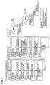
- the disk distinguishing apparatus includes a signal reading section 35, a tracking servo section 15, a focusing servo section 22, a spindle servo section 33, a disk distinguishing section 8, a DVD/CD signal processing section 28, and a focus search signal generation section 34 implemented by a microprocessor 37.
- Signal reading section 35 rotates by a spindle motor 3 an optical recording media 1 (specifically DVD or CD) to be distinguished, reads a signal by an optical pickup 2 to output it as a sensor signal.
- an optical recording media 1 specifically DVD or CD
- the optical pickup 2 used here is the one according to the liquid crystal shutter system, for example.
- the pickup of the liquid crystal shutter system blocks a laser beam directed onto an objective lens of the pickup by a liquid crystal shutter to change a numerical aperture (NA) such that the pickup is set into a mode corresponding to the DVD or the CD.
- NA numerical aperture
- the output sensor signal is supplied to tracking servo section 15, focus servo section 22, and DVD/CD signal processing section 28.
- Disk distinguishing section 8 identifies the type of disk by a focus error signal (FE signal) to output a disk type signal (Dtype signal).
- FE signal focus error signal
- Dtype signal disk type signal
- Each control section executes control according to Dtype signal.
- Tracking servo section 15 detects a tracking error from the sensor signal. Tracking servo section 15 executes tracking error detection 10 according to the phase difference method when Dtype signal identifies a DVD, and executes tracking error detection 11 according to the three-beam system when Dtype signal identifies a CD.
- An input to and the gain of an amplifier are thereafter changed by Dtype signal to be output to a tracking driver 5 through a loop filter 14.
- Focus servo section 22 detects a focus error from the sensor signal by the astigmatism method.
- the focus error signal is supplied to amplifiers 17, 18 and 19 corresponding to respective disks to be changed by Dtype signal, and the amplified one is output to a focus driver 6 through a loop filter 21 and switch 36.
- DVD/CD signal processing section 28 an RF signal is generated based on the sensor signal and amplified by an RF amplifier 24 and thereafter DVD signal processing 25 or CD signal processing 26 is performed according to Dtype signal.
- Spindle servo section 33 outputs a spindle error signal of the DVD or the CD corresponding to Dtype signal to a spindle driver 4 through a loop filter 32.
- the types of the disks are thus distinguished and accordingly switching of the pickup, rotation of the disk, focus control and tracking control suitable for each type of the disk are executed.
- disks are distinguished by disk distinguishing section 8 of a microcomputer 9.
- Step 1 - Step 5 of the flow chart focus search operation in a CD mode is performed, and in Step 6 - Step 11, focus search operation in a DVD mode is performed.
- Step 12 - Step 17 processes for distinguishing disks are performed.
- Step 1 a liquid crystal switch of the pickup of the liquid crystal shutter system is set into the CD mode, specifically an operation mode for reading signals from the CD.
- Step 2 focus search is started to detect the maximum value Max and the minimum value Min of a focus error signal.
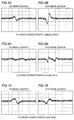
- the maximum value and the minimum value of the focus error signal are as shown in Figs. 3A, 3B, 4A, and 4B.
- the level of the focus error signal changes according to the distance between the pickup and the disk when the lens of the pickup is successively shifted in a region including a focusing region.
- the signal waveform observed in those figures represents a focus error detection feature referred to as S curve, and the operation of shifting the lens is referred to as focus search.
- the waveform of the focus error signal varies in accordance with the type of the disk and has characteristics listed below corresponding to a combination of the type of the disk and the operation mode of the pickup.
- the level of the focus error signal is high due to the presence of the focus.
- the waveform distorts and the level is low since there is out of focus.
- the level is low since the quantity of light is small although there is focus.
- the signal level of the dual-layer disk is normally lower than that of a single-layer disk.
- Step 5 a waveform level lvl_cd is determined as a difference between the maximum value Max and the minimum value Min.
- threshold values Th_h and Th_l are set at Max and Min respectively in order to apply a hysteretic signal processing.
- Step 7 the liquid crystal switch of the pickup is set into the DVD mode.
- Step 8 the focus search is started to detect the maximum value Max and the minimum value Min in Step 9.
- Hysterisis waveform shaping of the S curve signal is further executed, the number of rise or fall of the waveform is counted and the number is determined as N.
- a pair of threshold values of a higher one and a lower one are set, and the waveform level is set at an H level when the level exceeds the upper threshold value (Th_h) and at an L level when the waveform level thereafter becomes smaller than the lower threshold value (Th_l) as shown in Fig. 8.
- the waveform shaping thus eliminates the influence of noises between the threshold values.
- the influence of noises decreases as the waveform level approaches the maximum value and the minimum value as shown in Fig. 9.
- the maximum value or the minimum value of the waveform level is lower than the threshold value, the number of times the waveform of the S curve signal repeats cannot be counted correctly.
- the absolute level of the focus error signal disperses depending on the quantity of light or the signal level of the detector. Therefore, the number of repetitions could be counted erroneously if the threshold value is set at a fixed value.
- the threshold values are set based on the obtained signal level to perform the hysterisis shaping when the pickup is set into the DVD mode.
- Th_h and TH_l determined in Step 6 are accordingly used as the threshold values.
- Step 11 a difference between the maximum value Max and the minimum value Min is determined as waveform level lvl_dvd in Step 11.
- Step 12 a ratio R between lvl_cd and lvl_dvd is determined.
- Step 14 If N is determined to be at least 2 in Step 13, the disk type is identified as the dual DVD (Step 14).
- Step 15 If N is determined to be 1 or less in Step 13, in Step 15, R is compared with a reference value K which is set in advance.
- the disk type is identified as the single DVD (step 16).
- the disk type is identified as the CD.
- a disk type signal according to the disk type is thereafter supplied to each section of a control circuit (step 18).
- the disk type signal is supplied to tracking servo section 15, focus servo section 22, DVD/CD signal processing section 28 and spindle servo section 33 as Dtype signal described above, and each control section executes control according to Dtype signal.
- the embodiment is applicable to an ordinary multiple reproduction pickup according to the lens switching method or the like.
Landscapes
- Optical Recording Or Reproduction (AREA)
Applications Claiming Priority (2)
| Application Number | Priority Date | Filing Date | Title |
|---|---|---|---|
| JP9229507A JPH1166712A (ja) | 1997-08-26 | 1997-08-26 | ディスク判別方法 |
| JP229507/97 | 1997-08-26 |
Publications (2)
| Publication Number | Publication Date |
|---|---|
| EP0899732A1 true EP0899732A1 (de) | 1999-03-03 |
| EP0899732B1 EP0899732B1 (de) | 2006-10-11 |
Family
ID=16893266
Family Applications (1)
| Application Number | Title | Priority Date | Filing Date |
|---|---|---|---|
| EP98116025A Expired - Lifetime EP0899732B1 (de) | 1997-08-26 | 1998-08-25 | Verfahren zum Unterscheiden von Platten mit ähnlicher Reflektivität |
Country Status (6)
| Country | Link |
|---|---|
| US (1) | US6243341B1 (de) |
| EP (1) | EP0899732B1 (de) |
| JP (1) | JPH1166712A (de) |
| CN (2) | CN1114904C (de) |
| DE (1) | DE69836116T2 (de) |
| TW (1) | TW403902B (de) |
Cited By (2)
| Publication number | Priority date | Publication date | Assignee | Title |
|---|---|---|---|---|
| EP0987704A1 (de) * | 1998-09-18 | 2000-03-22 | Mitsumi Electric Company Ltd. | Optisches Plattenlaufwerk und Verfahren zur Unterscheidung von verschiedenen optischen Platten |
| EP1668637A1 (de) * | 2003-09-30 | 2006-06-14 | Samsung Electronics Co., Ltd. | Erkennungsverfahren und vorrichtung für optische datenträger |
Families Citing this family (19)
| Publication number | Priority date | Publication date | Assignee | Title |
|---|---|---|---|---|
| US6333907B1 (en) * | 1998-03-17 | 2001-12-25 | Kabushiki Kaisha Toshiba | Disk processing apparatus for reproducing information from a plurality of optical disks having different recording densities |
| JP2001101771A (ja) | 1998-04-14 | 2001-04-13 | Matsushita Electric Ind Co Ltd | ディスク判別方法 |
| CN1154985C (zh) * | 1998-07-03 | 2004-06-23 | 株式会社日立制作所 | 光检测器、信号处理电路、及其光信息再现设备 |
| JP3765235B2 (ja) * | 2001-02-16 | 2006-04-12 | 日本電気株式会社 | 光ディスク装置 |
| JP3788504B2 (ja) * | 2001-07-30 | 2006-06-21 | 船井電機株式会社 | 光ディスク判別方法及び光ディスク装置 |
| JP3649282B2 (ja) * | 2001-08-06 | 2005-05-18 | 船井電機株式会社 | ディスク装置及びフォーカシングサーボの起動方法 |
| KR100400009B1 (ko) * | 2001-08-25 | 2003-09-29 | 삼성전자주식회사 | 광 매체 판별 방법 및 장치 |
| DE60237024D1 (de) * | 2001-10-19 | 2010-08-26 | Sony Computer Entertainment Inc | Verfahren zum identifizieren des speichermediumtyps |
| KR100438783B1 (ko) | 2002-01-15 | 2004-07-05 | 삼성전자주식회사 | 디스크 판별 방법 |
| CN100437774C (zh) * | 2002-01-21 | 2008-11-26 | 松下电器产业株式会社 | 光盘装置及光盘判别方法 |
| JP2003233945A (ja) | 2002-02-07 | 2003-08-22 | Shinano Kenshi Co Ltd | 光ディスク装置およびその制御方法 |
| CN100341052C (zh) * | 2002-11-12 | 2007-10-03 | 三星电子株式会社 | 用于检测光盘类型和/或调节磁道平衡的装置和方法 |
| TWI227867B (en) * | 2002-12-26 | 2005-02-11 | Lite On It Corp | Method for discriminating compact disc type |
| KR20040107044A (ko) * | 2003-06-12 | 2004-12-20 | 삼성전자주식회사 | 광 디스크 판별 방법 및 그 장치 |
| TWI260000B (en) * | 2003-07-30 | 2006-08-11 | Mediatek Inc | Method for identifying the type of an optical disc |
| TWI266282B (en) * | 2003-10-24 | 2006-11-11 | Lite On It Corp | A method of judging a disk existence |
| TWI257605B (en) * | 2004-04-16 | 2006-07-01 | Asustek Comp Inc | Disc recognition method and apparatus |
| US20080175107A1 (en) * | 2007-01-19 | 2008-07-24 | Philips & Benq Digital Storage Corporation | Focusing control method for reading/writing optical disc |
| US7801003B2 (en) | 2007-06-04 | 2010-09-21 | Victor Company Of Japan, Limited | Optical disc type determining method and optical disc device |
Citations (5)
| Publication number | Priority date | Publication date | Assignee | Title |
|---|---|---|---|---|
| EP0727776A1 (de) * | 1995-02-20 | 1996-08-21 | Mitsubishi Denki Kabushiki Kaisha | Objektivlinsenantriebsvorrichtung und optische Informationsaufzeichnungs-/-wiedergabevorrichtung |
| JPH08293153A (ja) * | 1995-04-24 | 1996-11-05 | Matsushita Electric Ind Co Ltd | ディスク再生装置 |
| WO1997008691A1 (en) * | 1995-08-30 | 1997-03-06 | Samsung Electronics Co., Ltd. | Lens device and an optical pickup apparatus using the lens device |
| EP0790604A2 (de) * | 1996-02-13 | 1997-08-20 | Kabushiki Kaisha Toshiba | Wiedergabeanordnung für optische Platten |
| JPH1055602A (ja) * | 1996-08-08 | 1998-02-24 | Toshiba Corp | 光ディスク記録再生装置 |
Family Cites Families (5)
| Publication number | Priority date | Publication date | Assignee | Title |
|---|---|---|---|---|
| JPS6142751A (ja) | 1984-08-03 | 1986-03-01 | Sanyo Electric Co Ltd | 情報読取装置 |
| JP2598165B2 (ja) | 1990-11-29 | 1997-04-09 | ソニー株式会社 | 光ディスク記録再生装置 |
| JPH09106617A (ja) * | 1995-10-06 | 1997-04-22 | Pioneer Electron Corp | 情報記録媒体判別方法及び装置並びにフォーカスサーボ制御方法及び装置 |
| KR100197623B1 (ko) * | 1996-10-24 | 1999-06-15 | 윤종용 | 디스크종류판별방법 및 이를 적용한 dvd시스템 |
| JPH10214451A (ja) * | 1997-01-29 | 1998-08-11 | Alpine Electron Inc | デジタルディスクプレーヤ |
-
1997
- 1997-08-26 JP JP9229507A patent/JPH1166712A/ja active Pending
-
1998
- 1998-08-25 EP EP98116025A patent/EP0899732B1/de not_active Expired - Lifetime
- 1998-08-25 US US09/139,698 patent/US6243341B1/en not_active Expired - Lifetime
- 1998-08-25 DE DE69836116T patent/DE69836116T2/de not_active Expired - Fee Related
- 1998-08-25 TW TW087113956A patent/TW403902B/zh not_active IP Right Cessation
- 1998-08-26 CN CN98117939.8A patent/CN1114904C/zh not_active Expired - Fee Related
- 1998-08-26 CN CN02130229.4A patent/CN1224036C/zh not_active Expired - Fee Related
Patent Citations (5)
| Publication number | Priority date | Publication date | Assignee | Title |
|---|---|---|---|---|
| EP0727776A1 (de) * | 1995-02-20 | 1996-08-21 | Mitsubishi Denki Kabushiki Kaisha | Objektivlinsenantriebsvorrichtung und optische Informationsaufzeichnungs-/-wiedergabevorrichtung |
| JPH08293153A (ja) * | 1995-04-24 | 1996-11-05 | Matsushita Electric Ind Co Ltd | ディスク再生装置 |
| WO1997008691A1 (en) * | 1995-08-30 | 1997-03-06 | Samsung Electronics Co., Ltd. | Lens device and an optical pickup apparatus using the lens device |
| EP0790604A2 (de) * | 1996-02-13 | 1997-08-20 | Kabushiki Kaisha Toshiba | Wiedergabeanordnung für optische Platten |
| JPH1055602A (ja) * | 1996-08-08 | 1998-02-24 | Toshiba Corp | 光ディスク記録再生装置 |
Non-Patent Citations (2)
| Title |
|---|
| DATABASE WPI Week 9818, Derwent World Patents Index; AN 98-203223, XP002086097 * |
| PATENT ABSTRACTS OF JAPAN vol. 097, no. 003 31 March 1997 (1997-03-31) * |
Cited By (4)
| Publication number | Priority date | Publication date | Assignee | Title |
|---|---|---|---|---|
| EP0987704A1 (de) * | 1998-09-18 | 2000-03-22 | Mitsumi Electric Company Ltd. | Optisches Plattenlaufwerk und Verfahren zur Unterscheidung von verschiedenen optischen Platten |
| US6760289B1 (en) | 1998-09-18 | 2004-07-06 | Koji Ide | Optical disc drive and method of discriminating various types of optical discs |
| EP1668637A1 (de) * | 2003-09-30 | 2006-06-14 | Samsung Electronics Co., Ltd. | Erkennungsverfahren und vorrichtung für optische datenträger |
| EP1668637A4 (de) * | 2003-09-30 | 2008-09-10 | Samsung Electronics Co Ltd | Erkennungsverfahren und vorrichtung für optische datenträger |
Also Published As
| Publication number | Publication date |
|---|---|
| DE69836116D1 (de) | 2006-11-23 |
| EP0899732B1 (de) | 2006-10-11 |
| CN1492421A (zh) | 2004-04-28 |
| JPH1166712A (ja) | 1999-03-09 |
| CN1114904C (zh) | 2003-07-16 |
| US6243341B1 (en) | 2001-06-05 |
| CN1211029A (zh) | 1999-03-17 |
| CN1224036C (zh) | 2005-10-19 |
| TW403902B (en) | 2000-09-01 |
| DE69836116T2 (de) | 2007-05-16 |
Similar Documents
| Publication | Publication Date | Title |
|---|---|---|
| US6243341B1 (en) | Method of distinguishing disks having nearly the same reflectance | |
| US7406014B2 (en) | Disc discriminating method and information reproducing apparatus using thereof | |
| EP0840295B1 (de) | Initialisierung von Systemen mit optischen Platten | |
| JP3619625B2 (ja) | ディスク判別装置および方法 | |
| JP2000311427A (ja) | ディスク判別方法および装置 | |
| KR100958582B1 (ko) | 기록가능한 디스크의 판별 방법 및 그 장치 | |
| US6646962B2 (en) | Apparatus for detecting dropout, an error signal extracting unit, and unit for identifying type of dropout in an optical pickup | |
| US20050201253A1 (en) | Optical reproducing apparatus and method with automatic gain control | |
| KR20040070749A (ko) | 광디스크 종류 판별장치 및 방법 | |
| US7385895B2 (en) | Method of discriminating optical disc type and apparatus thereof | |
| US7038986B2 (en) | Method and apparatus for discriminating between different types of discs | |
| US20040100890A1 (en) | Method and apparatus for discriminating a disc type | |
| KR100272366B1 (ko) | 디스크판별방법 | |
| US20040037178A1 (en) | Method of detecting imbalanced disk in disk drive apparatus and disk drive apparatus | |
| KR100243163B1 (ko) | 광디스크 재생장치 | |
| US7512047B2 (en) | Apparatus and method for reading from and/or writing to optical recording media | |
| KR100850920B1 (ko) | 광디스크의 트랙킹 서보 제어장치 및 제어방법 | |
| JP2629676B2 (ja) | 光ディスクの再生装置 | |
| JPH08180409A (ja) | 光ディスク録再装置 | |
| KR19990038613A (ko) | 광 디스크 판별장치 및 방법 | |
| KR20060057068A (ko) | 광디스크 기기에서의 트래킹 서보 제어장치 및 방법 | |
| EP1162609A2 (de) | Plattenwiedergabegerät und Plattenwiedergabeverfahren | |
| JPH0371439A (ja) | 光ディスク装置のトラッキングサーボ方法及びその装置 | |
| KR20040043939A (ko) | 광 디스크 판별 방법 및 그 장치 | |
| JP2005085374A (ja) | 光ディスク再生装置 |
Legal Events
| Date | Code | Title | Description |
|---|---|---|---|
| PUAI | Public reference made under article 153(3) epc to a published international application that has entered the european phase |
Free format text: ORIGINAL CODE: 0009012 |
|
| AK | Designated contracting states |
Kind code of ref document: A1 Designated state(s): DE FR GB |
|
| AX | Request for extension of the european patent |
Free format text: AL;LT;LV;MK;RO;SI |
|
| 17P | Request for examination filed |
Effective date: 19990212 |
|
| AKX | Designation fees paid |
Free format text: DE FR GB |
|
| 17Q | First examination report despatched |
Effective date: 20041228 |
|
| GRAP | Despatch of communication of intention to grant a patent |
Free format text: ORIGINAL CODE: EPIDOSNIGR1 |
|
| GRAS | Grant fee paid |
Free format text: ORIGINAL CODE: EPIDOSNIGR3 |
|
| GRAA | (expected) grant |
Free format text: ORIGINAL CODE: 0009210 |
|
| AK | Designated contracting states |
Kind code of ref document: B1 Designated state(s): DE FR GB |
|
| REG | Reference to a national code |
Ref country code: GB Ref legal event code: FG4D |
|
| REF | Corresponds to: |
Ref document number: 69836116 Country of ref document: DE Date of ref document: 20061123 Kind code of ref document: P |
|
| ET | Fr: translation filed | ||
| PLBE | No opposition filed within time limit |
Free format text: ORIGINAL CODE: 0009261 |
|
| STAA | Information on the status of an ep patent application or granted ep patent |
Free format text: STATUS: NO OPPOSITION FILED WITHIN TIME LIMIT |
|
| 26N | No opposition filed |
Effective date: 20070712 |
|
| PGFP | Annual fee paid to national office [announced via postgrant information from national office to epo] |
Ref country code: DE Payment date: 20080905 Year of fee payment: 11 |
|
| PGFP | Annual fee paid to national office [announced via postgrant information from national office to epo] |
Ref country code: FR Payment date: 20080818 Year of fee payment: 11 |
|
| PGFP | Annual fee paid to national office [announced via postgrant information from national office to epo] |
Ref country code: GB Payment date: 20080903 Year of fee payment: 11 |
|
| GBPC | Gb: european patent ceased through non-payment of renewal fee |
Effective date: 20090825 |
|
| REG | Reference to a national code |
Ref country code: FR Ref legal event code: ST Effective date: 20100430 |
|
| PG25 | Lapsed in a contracting state [announced via postgrant information from national office to epo] |
Ref country code: FR Free format text: LAPSE BECAUSE OF NON-PAYMENT OF DUE FEES Effective date: 20090831 Ref country code: DE Free format text: LAPSE BECAUSE OF NON-PAYMENT OF DUE FEES Effective date: 20100302 |
|
| PG25 | Lapsed in a contracting state [announced via postgrant information from national office to epo] |
Ref country code: GB Free format text: LAPSE BECAUSE OF NON-PAYMENT OF DUE FEES Effective date: 20090825 |