EP0898163B1 - Procédé et appareil d'inspection automatique des surfaces en mouvement - Google Patents
Procédé et appareil d'inspection automatique des surfaces en mouvement Download PDFInfo
- Publication number
- EP0898163B1 EP0898163B1 EP97114590A EP97114590A EP0898163B1 EP 0898163 B1 EP0898163 B1 EP 0898163B1 EP 97114590 A EP97114590 A EP 97114590A EP 97114590 A EP97114590 A EP 97114590A EP 0898163 B1 EP0898163 B1 EP 0898163B1
- Authority
- EP
- European Patent Office
- Prior art keywords
- light
- signal
- spectral characteristic
- illumination
- sensitive sensor
- Prior art date
- Legal status (The legal status is an assumption and is not a legal conclusion. Google has not performed a legal analysis and makes no representation as to the accuracy of the status listed.)
- Expired - Lifetime
Links
Images


Classifications
-
- G—PHYSICS
- G01—MEASURING; TESTING
- G01N—INVESTIGATING OR ANALYSING MATERIALS BY DETERMINING THEIR CHEMICAL OR PHYSICAL PROPERTIES
- G01N21/00—Investigating or analysing materials by the use of optical means, i.e. using sub-millimetre waves, infrared, visible or ultraviolet light
- G01N21/84—Systems specially adapted for particular applications
- G01N21/88—Investigating the presence of flaws or contamination
- G01N21/89—Investigating the presence of flaws or contamination in moving material, e.g. running paper or textiles
- G01N21/8901—Optical details; Scanning details
-
- C—CHEMISTRY; METALLURGY
- C23—COATING METALLIC MATERIAL; COATING MATERIAL WITH METALLIC MATERIAL; CHEMICAL SURFACE TREATMENT; DIFFUSION TREATMENT OF METALLIC MATERIAL; COATING BY VACUUM EVAPORATION, BY SPUTTERING, BY ION IMPLANTATION OR BY CHEMICAL VAPOUR DEPOSITION, IN GENERAL; INHIBITING CORROSION OF METALLIC MATERIAL OR INCRUSTATION IN GENERAL
- C23G—CLEANING OR DE-GREASING OF METALLIC MATERIAL BY CHEMICAL METHODS OTHER THAN ELECTROLYSIS
- C23G3/00—Apparatus for cleaning or pickling metallic material
- C23G3/02—Apparatus for cleaning or pickling metallic material for cleaning wires, strips, filaments continuously
- C23G3/027—Associated apparatus, e.g. for pretreating or after-treating
-
- G—PHYSICS
- G01—MEASURING; TESTING
- G01N—INVESTIGATING OR ANALYSING MATERIALS BY DETERMINING THEIR CHEMICAL OR PHYSICAL PROPERTIES
- G01N21/00—Investigating or analysing materials by the use of optical means, i.e. using sub-millimetre waves, infrared, visible or ultraviolet light
- G01N21/84—Systems specially adapted for particular applications
- G01N21/88—Investigating the presence of flaws or contamination
- G01N21/8806—Specially adapted optical and illumination features
- G01N2021/8822—Dark field detection
- G01N2021/8825—Separate detection of dark field and bright field
Definitions
- the present invention relates to a method and to an apparatus for automatic inspection of moving surfaces, in particular to a method and an apparatus for automatic inspection of moving surfaces for applications such as the inspection of steel strips, wood, leather or tiles. Even more particularly, the present invention relates to a method and an apparatus for automatic inspection of moving surfaces using at least three different illumination/observation channels.
- Products like the above-mentioned steel strips, wood, leather or tiles are typically produced at high speed in a continuous process and they have to be inspected during motion.
- the defects which have to be detected and classified automatically are anomalies in the surfaces with respect to e.g. reflectivity, color, glossiness, texture and the 3D-profile of the surface under inspection.
- the applied cameras are monochrome or color line scan cameras.
- fluorescent lamps, halogen lamps or fiber optic illuminators are commonly used.
- the defects to be detected and classified are e.g. scratches, dents, knots and the like as defined by the application. Typically these defects manifest themselves in different ways, e.g. in deviations of reflectivity, glossiness, color, texture or the 3D-profile of the surface under inspection.
- a critical part in the system design is to define the apparatus for image acquisition, including the selection of a camera and the illumination system, and to determine the geometrical relations of the components.
- the aim is to achieve images from the surface which contain the necessary information to detect and to distinguish all of the defects automatically, including 3D-defects. In many cases the result is disappointing. The reason is simply that monocular images do not contain reliable and unambiguous information on the 3D-profile and glossiness of the surface.
- a multi-camera setup is used in some applications by means of which the surface is inspected under different viewing conditions simultaneously. In such setups, typically two monochromatic cameras and one illuminator are used to obtain bright and dark field images of the same object.
- the technique is named photometric stereo because it uses the radiance values recorded at a single pixel location in successive views, rather than the relative positions of displaced features in binocular stereo. Since the viewing geometry in this technique is not changed, the correspondence between pixels in the taken set of images is known a priori.
- the photometric stereo method requires that the inspected object be fixed relative to the imaging hardware, giving time to switch the lamps and to take the images, and that the reflectance distribution of the surface is known. Therefore, the method cannot be applied for inspection of moving materials and surfaces of unknown reflectivity.
- DE 195 11 534 A1 relates to a method and an apparatus for detecting 3D-defects, such as dents and steps in a flat surface, in applications for automatic surface inspection, following the idea of photometric stereo.
- the surface under inspection is simultaneously illuminated with at least two lamps from different directions under dark field conditions, where the light from the lamps has different colors.
- a color line scan camera is used for image acquisition and 3D-defects are detected by analyzing the measured color values.
- This method yields information on 3D-defects but not on glossiness and reflectivity of the surface because a symmetrical dark field illumination is used. Therefore, the capabilities for discriminating between different types of defects are limited. Furthermore, defect detection is done by a color classifier. Using this method it is not possible to adapt to a changing appearance of the inspected surface or to changes of the illumination. In practical applications, the sensitivity for defect detection is limited.
- EP 0 764 845 A2 describes an apparatus for image acquisition which is similar to the one described in DE 195 11 534 A1, but the method for the detection of 3D-defects is only based on shadows, which can be observed at the edges of steps in the surface.
- JP-A-06058731 relates to a pattern inspecting apparatus for inspecting a 3D shape of a pattern of a wiring board.
- Lights of three primary colors, blue, green and red, are applied to one surface of the wiring board as well as to the rear of the wiring board.
- a color television camera picks up an image of the board and converts the optical image of the surface thereof into video signals of the three primary colors of the lights.
- the width of a pattern on the wiring board as well as the quality of the pattern is determined.
- WO-A-9418643 concerns a method and an apparatus for imaging the surface of an object which is moved through an inspection region where it is illuminated. As the object moves through an inspection region, a portion of the illumination means illuminates the object under dark field illumination and a portion of the illumination means illuminates the object under bright field illumination. An imaging means for imaging the object within the inspection region to produce a composite image is also provided.
- the present invention provides a method and an apparatus for automatic surface inspection which makes it possible to extract and to process information on the physical properties of the surface, like reflectivity, glossiness and slope of surface elements separately.
- the advantage is that especially 3D-defects can be detected and classified with high reliability even in textured surfaces.
- Applications are e.g. the inspection of steel, leather, wood, extruded profiles or other materials, which are produced in a continuous process with a high speed and have to be inspected during motion.
- the present invention is based on the idea of photometric stereo.
- Information on reflectivity, color, glossiness and profile of the inspected surface is captured, e.g. by an apparatus comprising a color line scan camera and at least three spatially separated light sources with different spectral characteristics.
- the result of the image acquisition are registered images, e.g. R-, G-, B-images, basically corresponding to the channels of illumination.
- These images are processed in several steps comprising estimation of physical properties for each surface element, detection of surface anomalies, feature extraction and classification.
- the first illumination/observation channel is formed by a light sensitive sensor device and a first light source
- the second illumination/observation channel is formed by the same light sensitive sensor device and by a second light source
- the third illumination/observation channel is formed by the same light sensitive sensor device and a third light source.
- the first illumination/observation channel is formed by a first light sensitive sensor device and by a light source
- the second illumination/observation channel is formed by a second light sensitive sensor device and the same light source
- the third illumination/observation channel is formed by a third light sensitive device and the same light source.
- information on reflectivity, glossiness and slope from a moving surface are extracted separately from the surface element under inspection and based on this information the surfaces are inspected with enhanced reliability at less false alarm rate.
- step S100 an image of the moving surface under inspection is acquired.
- the apparatus schematically shown at step S100 in Fig. 1 will be described with reference to Fig. 3 hereinafter.
- step S102 physical properties of the inspected surface element are estimated on the basis of the acquired image.
- step S104 anomalies in the physical properties of the surface are detected.
- step S106 specific features are extracted and in step S108 the detected regions are classified.
- step S110 a decision is made whether the inspected surface is acceptable, i.e. fulfills predetermined requirements with respect to the physical properties, or whether the surface exhibits defects.
- the image acquired in step S100 is formed from three different images which is illustrated by the arrows 100a, 100b and 100c between step S100 and step S102.
- the three images are represented by three video signals, wherein a first signal 100a representing a first image is obtained by observing the surface to be inspected under a first observation condition by means of a first of at least three different illumination/observation channels.
- the second and the third signals on line 100b and 100c, respectively, are obtained by observing the surface under a second observation condition by means of a second and a third of the at least three different illumination/observation channels.
- second and third signals physical properties of the surface elements are derived in step S102.
- step S100 information on reflectivity, color, glossiness and profile of the inspected surface is captured by an apparatus with a color line scan camera and three spatially separated light sources with different spectral characteristics, following the above outlined idea of photometric stereo.
- the result of the image acquisition in step S100 are in this embodiment three registered images (R, G, B) basically corresponding to three channels of illumination.
- the images are processed as follows:
- step S102 the physical property or properties for each surface element are estimated and the result are physical property images representing reflectivity, color, glossiness and slope of the surface element, as it is illustrated by the four arrows between block S102 and block S104. These images have the same spatial resolution as the original image.
- step S104 the anomalies are detected. Local anomalies within the property images are detected at the same spatial resolution as the original image, and regional anomalies, e.g. due to a shallow wave in the surface or surface roughness, are detected by computing the moving average or the moving standard deviation of the slope of the surface elements followed by a comparison of the resulting statistical figures with thresholds.
- the output of step S 104 are multiple binary images, as indicated by the plurality of arrows connecting step S104 and step S106.
- step S106 features from the binary images generated in step S104 are extracted.
- Simple or complex geometrical features are calculated, such as the area and shape of blobs in the binary images.
- neighborhood relations can be taken into account, e.g. accumulation of blobs, or the overlap of blobs within different layers of the multiple binary images received from step S104.
- step S108 the classification is carried out and the segmented regions of the detection image are classified due to the extracted features.
- Fig. 2 Prior to describing preferred embodiments of the inventive apparatus and the inventive method, with respect to Fig. 2 it is illustrated how light is scattered dependent from the reflectivity, glossiness and slope, respectively, of a surface.
- the apparatus according to the present invention which is used for image acquisition is, according to a preferred embodiment, intended to gather information on reflectivity, glossiness, color and slope of the surface elements under inspection.
- the apparatus and method described below are based on considerations as illustrated in Fig. 2 which shows the way how light will be scattered from a surface element if it is illuminated by a ray of light which is incident orthogonal to the inspected surface.
- Fig. 2a the scattering characteristics with respect to the reflectivity of a surface S are shown.
- a beam of light 200 is incident orthogonal to the surface S and light beams 202 are reemitted from the surface S.
- a line 204 is drawn around the reemitted beams 202 indicating the lobe of the reflected light.
- the energy of the reemitted light will be low, as it is indicated by the small lobe 204 indicating a low volume V 1 of the reflected light distribution.
- the energy of reemitted light will be high, as it is illustrated by the large lobe 204, i.e. the volume V 2 of the reflected light distribution is high.
- the shape of the light distribution i.e. the lobes 204, will be the same.
- Fig. 2b the light distribution of the reemitted light for a different glossiness of the surface S is illustrated. Again a beam light of 200 is incident orthogonal to the surface S. In case of a low glossiness of the surface S (left-hand side of Fig. 2b) the light distribution as indicated by lobe 204 will be broad. For a high glossiness of surface S (right-hand side of Fig. 2b) the light distribution, again indicated by lobe 204, will be slim.
- the reflected light distribution indicated by the volumes V 1 and V 2 is supposed to be the same in case of a low glossiness of the surface S and for a surface S of high glossiness in this example.
- Fig. 2c the reflected light distribution in case of a slope in surface S is shown. Again a beam of light 200 is incident orthogonal to surface S and the reflected light distribution is again indicated by lobe 204, whereas the amount of reflected light is again indicated by the volumes V 1 and V 2 .
- the light distribution 204 will be symmetrical with respect to the surface normal, and it will be tilted if the surface element S has a slope 206.
- the volumes V 1 and V 2 are the same in both cases.
- the different shapes of the lobes 204 and volumes V 1 , V 2 of the reemitted light distribution can be discriminated by simultaneously observing the illuminated surface element with several light sensitive sensors from different directions. The same will be true, if the light source used in Fig. 2 for illuminating the surface S with the beam of light 200 is replaced by a single light sensitive sensor, like a camera, and if the sensors are replaced by light sources.
- the apparatus in Fig. 3 is one preferred embodiment of the present invention and is indicated by reference sign 300.
- the apparatus 300 comprises a camera C which is a color line scan camera.
- the camera C comprises a lens 304 and a processing section 306 for generating signals representing the received images.
- Section 306 has three outputs R, G, B wherein the signals are representing a red image (R), a green image (G) and a blue image (B).
- the camera C is arranged above the surface S to be inspected in such manner that the normal 308 of surface S is coincident with the axis of observation 310 of the camera C.
- light sources L1, L2 and L3 emitting light beams 312, 314 and 316 of different spectral characteristics are provided.
- Light from the respective light sources is viewn under an angle ⁇ by the inspected line of the surface.
- the light beams 312 from the first light source L1 are directed via a mirror M towards the surface S in such a manner that they are incident orthogonal onto surface S.
- the light sources L2 and L3 are arranged such that the respective beams of light 314 and 316 emitted from the light sources enclose with the normal 308 of the surface S an angle ⁇ .
- Light source L1 is illuminating surface S under bright field conditions by means of the mirror M, which can be a beam splitting mirror.
- Light sources L2 and L3 illuminate the surface S under symmetrical dark field conditions.
- a bright field condition is a condition under which light emitted, e.g. by light source L1, is reflected from a specular surface S back towards the lens 304 of camera C.
- a dark field condition is a condition under which, in case of a non-defective surface, light, e.g. emitted by light source L2 is not reflected towards the lens 304 of camera C from a specular surface.
- the angle ⁇ and ⁇ can be chosen in accordance with the demands of the application for optimized sensitivity and robustness of the measurements. E.g. for glossy surfaces ⁇ has to be small.
- Fig. 4 the same reference signs are used for identical elements, which have already been described with reference to Fig. 3.
- the difference between the apparatus shown in Fig. 4 and the apparatus shown in Fig. 3 is that the axis of observation 310 of camera C and the beams of light 312 emitted from light source L1 are not coincident with the normal 308 of surface S.
- the axis of observation 310 and normal 308 as well as the beams of light 312 of light source L1 and the normal 308 enclose an angle ⁇ .
- the first illumination/observation channel is formed by a light sensitive sensor device which is according to Fig. 3 and 4 the camera C and by the first light source L1, wherein the camera C receives light of the first beam 312 of light reemitted from the surface element S.
- the second illumination/observation channel is formed by the light sensitive sensor device C and the second light source L2 and the light sensitive sensor device or camera C receives light of the second beam 314 of light reemitted from the surface element S.
- the third illumination/observation channel is formed by the light sensitive sensor device or camera C and the third light source L3, and the camera C receives light of the third beam 316 of light reemitted from the surface element S.
- the three beams 312, 314 and 316 of light all have different characteristics, and according to a specific embodiment have different spectral characteristics, i.e. different colors.
- the second light source L2 and third light source L3 operating under a dark field condition are arranged symmetrically with respect to the normal 308 of surface S or with respect to the first beam of light 312 emitted from the first light source L1. It is, however, noted that the light sources L2 and L3 can be arranged in a non-symmetrically manner. As to the position of the first lamp L1 it is noted that same may deviate somewhat from the exact specular direction shown in Fig. 4 without disturbing the bright field condition. Further to the described embodiment, the second and the third light source can be symmetrically arranged with respect to the normal 308 of the surface S or with respect to the first beam of light 312 emitted from the first light source L1.
- the above described principle underlying the present invention is, however, not restricted to three channels of illumination and three color channels of the camera, or more broadly speaking to only three illumination/observation channels, but can be extended to N channels of illumination and observation.
- the light sources L1, L2 and L3 may be simply colored fluorescent lamps. They can also be rows of halogen lamps equipped with color filters, or they can be built by using collimated fibre optics. The latter realization has the advantage of a very bright and even illumination of the inspected line of surface S, which is necessary in high speed applications, especially because the dark field illumination used in photometric stereo requires a lot of light.
- any incandescant lamp, gas discharge lamps (colored or wide spectrum), LEDs, and Lasers can be used for illuminating the surface.
- the three characteristic angles ⁇ , ⁇ and ⁇ in the apparatus for image acquisition as shown in Fig. 3 and Fig. 4 can be chosen independently in any of the mentioned relationships for illumination.
- the angle ⁇ has to be selected carefully in order to detect shiny defects.
- this angle can be determined by changing the distance between the lamps and the inspected surface or by adding mirrors behind the lamps or by adding more fluorescent tubes.
- the used light sources are not point light sources but are somewhat expanded.
- Fig. 3 it is assumed that fluorescent tubes are used which extend perpendicular to the direction of motion of the surface. In the direction of motion of the surface the extension is defined by the diameter of the tubes. Based on the distance of the tubes from the observed line on the surface and the diameter of the tubes the angle ⁇ (gamma) is determined under which the surface is illuminated by light. It is preferred that the angle ⁇ can be varied as shown in Fig. 5. In case of fluorescent tubes this variation can be achieved by changing the distance between the tubes and the surface, by partially covering the tubes or, as shown in Fig. 5, by arranging a plurality of tubes in parallel.
- a light source 500 emitting a beam of light 502 is used for illuminating a surface S which is moved into a direction which is indicated by arrow 504.
- the incident beam of light 502 is reflected at a defect portion 506 of surface S and the distribution of the reflected light energy is indicated by means of lobe 508.
- the camera C is arranged above the surface S in such a manner that its axis of observation 310 is coincident with the normal 308 of surface
- Fig. 5b a similar arrangement is shown, in which the light source 500 is replaced by three light sources 500a, 500b and 500c emitting respective beams of light 502a, 502b and 502c which results in a distribution of the reflected energy as indicated by lobes 508a, 508b and 508c.
- the light sources 500a, 500b and 500c are formed by a multiple fibre optic. From a comparison of Fig. 5a and 5b it becomes clear that a wide angle dark field illumination with multiple fibre optics as shown in Fig. 5b is to be preferred, since the benefits of such an arrangement are an enhanced light level of the illumination and an enhanced probability for detection of reflections from shiny defects.
- the apparatus 600 comprises the camera C which is arranged above the surface S, the direction of motion of surface S would be out of the plane of Fig. 6.
- the apparatus 600 comprises three standard fibre illuminators F1, F2 and F3.
- the field of observation of the camera C is limited as shown by the two dashed lines 602 and 604.
- the illumination range of fibre illuminator F1 indicated by dashed lines 606 and 608 is such that light from the first illuminator F1 which is reflected by the surface S is directed towards camera C such that illuminator F1 operates under a bright field condition.
- Fibre illuminator F2 has a range in which light is emitted, which is limited as indicated by dashed line 610
- illuminator F3 has a range of illuminating the surface S which is limited as indicated by dashed line 612.
- Illuminators F2 and F3 operate under a dark field condition, i.e. in case of a non-defective surface, the light from illuminators F2 and F3 reflected by a specular surface S is not directed towards the lens 304 of camera C.
- the indicated range of illumination of illuminators F2 and F3 is achieved by arranging same in a tilted position under a required illumination angle.
- Illuminator F1 may be aligned with camera C. Basically the bright field illuminator F1 is positioned in the same way as the light source or lamp L1 is in Fig. 4. Instead of fibre illuminators F1, F2 and F3, illuminators like halogen lamps with color filters can be used.
- This construction is not sensitive to height variations and vibrations of the surface, but suffers from a sloping illumination profile. Depending on the reflectivity of the surface this may or may not be problematic. If the surface is not very specular, the uneven illumination can be compensated by a proper correction of the resulting video signal, without loosing a lot of dynamic range at the borders of the illuminated area.
- Fig. 7 a preferred embodiment of a side illumination is described.
- a fibre optic 700 To illuminate the surface S under inspection a fibre optic 700 is used.
- the fibre optic is connected via a suited wave guide to a light source (not shown).
- the fibre optic 700 emitts light under different angles of illumination, as can be seen from Fig. 7b.
- a first plurality of light beams 704 and a second plurality of light beams 706 are used to achieve a dark field illumination of surface S.
- rays or beams 704 and 706, when reflected by a specular surface S having no defects are not directed towards the lens 304 of camera C.
- a plurality of beams 708 is directed orthogonal towards the surface S and provides the bright field illumination of surface S, since light from beam 708 is directly reflected towards the lens of camera C.
- Fig. 7a the emitted light beams are shown in a side view and are indicated by reference sign 710.
- the light beams are collimated.
- the fibre optic 700 comprises a first cover layer 802 and a second cover layer 804 in between which three fibre layers 806, 808 and 810 are sandwiched.
- Fibre layer 808 comprises, like the remaining fibre layers 806 and 810 a plurality of single fibres 808 to form a bundle of fibres which are orientated in the direction as indicated by arrow 808b.
- Fibre layer 806 also comprises a plurality of fibres 806a which are arranged in a tilted position when compared with the arrangement of the fibres 808a in layer 808, as it is indicated by arrow 806b.
- fibre layer 810 comprises a plurality of fibres 810a which are tilted with respect to the fibres 808a in layer 808, but in a different direction than the tilted fibres 806a in layer 806, as it is indicated by arrow 810b.
- the different angles of illumination are constructed inside of one single fibre illuminator. This is achieved, as shown in Fig. 8, by splitting the fibre 700 into several layers 806 to 810, wherein each of the layers 806 to 810 corresponds to one of the required channels for illumination.
- the different angles of illumination are achieved by tilting the fibres 806a and 810a of the respective layer 806 and 810 into the angle that corresponds to the required illumination angle, when taking Snell's law into account.
- more than one layer per angle of illumination can be used.
- sandwiched layers of fibre optics it is also possible to use an arrangement having one fibre layer with straight fibres for illumination under the bright field condition and to use an integrated pair of fibre layers having tilted fibres for the dark field illumination.
- three separate fibre layers for illuminating the surface under the bright field condition and under the dark field condition may be used.
- an arrangement using e.g. two or more of the sandwiched construction of fibre layers enables an illumination of the surface in more than three directions.
- the tilted fiber illuminators can produce one or more illumination directions and can consist of one or more fibre layers per illumination direction.
- the dark field illumination used in the photometric stereo method typically requires a lot of light.
- the current solutions often apply high frequency or DC powered halogen lamps for the dark field illumination. These solutions are inexpensive, but the spectrum of the halogen lamps is relatively weak in the visible area, especially in the green and blue regions, and much more powerful in the near infrared and infrared portion of the spectrum.
- the spectrally superior metal halide lamps are generally not used, since the normal AC powered metal halide lamps produce horizontal stripes in images, which are known as the 100Hz modulation. This modulation is due to the fact that the metal halide lamp is practically black between the phases of the applied voltage. High frequency and DC power supplies for metal halide lamps are very expensive and typically not even available for short arc lamps with more than 100 W of power.
- a lamp unit 900 and a control unit 902 is shown.
- the lamp unit 900 includes a first, a second and a third metal halide lamp L1, L2 and L3 which are controlled by respective control elements 902a, 902b and 902c in the control unit 902.
- the control elements 902a through 902c receive via lines 904a, 904b and 904c a power.
- the power applied to the respective control elements 902a to 902c are different in phase.
- Each lamp L1, L2 and L3 is provided with either ellipsoid reflectors or focusing lenses to focus the light emitted from the lamps L1, L2 and L3 to associated filter elements F1, F2 and F3 to provide a lamp unit output on fibre bundles 908a, 908b and 908c of different color.
- Optional IR-filters 906a, 906b and 906c can be used to block the IR-component of light to protect the fibre bundles from extra heat.
- the control unit 902 controls the metal halide lamps L1 through L3 by a three phase AC power applied via lines 904a, 904b and 904c.
- the lamps are connected to a fibre line having the fibre bundles 908a, 908b and 908c, wherein the fibre line has a randomized fibre construction.
- the lamps are connected to the fibre line in groups of three lamps so that each of these lamps is running at a 120° phase shift compared to the others. If the fibres are properly randomized in the fibre line, the resulting illumination output is not zero at any time, and this results in a reduced amount of ripples in the image. The remaining ripples can be easily removed from the image by well known means of analog or digital signal processing.
- the arrangement shown in Fig. 9 has the benefit that efficient metal halide lamps can be used without limiting and expensive republic.
- the differently colored light components are produced by the color filters F1, F2 and F3 and separate lamps L1, L2 and L3 are used for each color.
- the arrangement shown in the lamp unit 900 a preferred choice is to use an arrangement as it will be described with reference to Fig. 10. Further to the above described metal halide lamps any AC-driven lamps can be used.
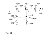
- FIG. 10 an arrangement is shown, which uses only one lamp to produce the three colors.
- a beam of light 1000 from a lamp is directed onto a blue-reflective filter 1002 which transmit only light of red and green color as indicated by arrow 1004 and reflects light of blue color as indicated by arrow 1006.
- the blue light is then again filtered by means of a blue filter 1008 and at a first output 1010 the blue light is output.
- the red and green light beam is directed to a red-reflective filter 1012 which transmits green light as indicated by arrow 1014 and reflects red light as indicated by arrow 1016.
- the transmitted green light is passed through a green filter 1018 and at a second output 1020 a beam of green light is output.
- the red light reflected by filter 1012 is directed to a red filter 1022 and at a third output 1024 a beam of red light is output.
- a red filter 1022 As can be seen from Fig. 10 all color components are produced from one single lamp and in this case, the amount of lamps can, in principle, reduced by a factor of three. If appropriate dichroic filters are used, the additional color filters 1008, 1018 and 1022 are not needed.
- Fig. 11 shows a block diagram of the first three steps S100, S102, and S104 as described with reference to Fig. 1.
- the signals acquired by means of the camera C are in the described embodiment signals representing a red image (R), a green image (G) and a blue image (B).
- the three images are input into block 1100 in which a channel separation is carried out.
- Block 1100 outputs three separated signals representative of the influence of the three channels of illumination.
- the signals x R , x G and x B are input into respective filters 1102, 1104 and 1106, as well as into respective blocks 1108, 1110, 1112 for expressing deviations in the signals not as differences from the average but as contrast.
- the calculations carried out in block 1108, 1110 and 1112 are made on the basis of the signals received from block 1100 and on the signals received from the respective filters 1102, 1104 and 1106 which output an average signal value of the signal output from block 1100.
- Block 1108 outputs a signal representative of the bright field
- block 1110 outputs a signal representative of the left channel dark field
- block 1112 outputs a signal representative of the right channel dark field.
- Block 1114 substracts from the bright field the dark field for the left channel and for the right channel and outputs a signal representing the glossiness of the inspected surface element.
- Block 1118 forms a difference between the left channel dark field and the right channel dark field and outputs a signal representing the slope in the surface under inspection.
- Block 1118 sums the bright field and the two dark fields and outputs a signal representative of the reflectivity of the surface under inspection.
- the signals indicative of the glossiness, slope and reflectivity are input into block 1120 which detects anomalies on the basis of specific statistics and by thresholding the received signals.
- Block 1120 outputs further signals for the further processing described with reference to Fig. 1, namely the feature extraction, the classification and decision.
- the signals R, G and B from the camera C are also input into a color classifier 1122 which outputs a signal indicating miscolored regions of the surface which is also used for the further processing of the detection images output by block 1120.
- the first aim is to estimate the physical properties of the surface element under inspection from the video signal (R, G, B) of the camera C.
- the spectral distribution of the three channels R, G, B of the color line scan camera C will show some overlap and/or the spectral distribution of the light sources will not meet exactly the color channels of the camera C.
- there will be some crosstalk between the three channels of illumination which can be eliminated by measuring the crosstalk for a non-defective surface and substracting for each channel R, G, B the respective fractions of crosstalk from the other two channels, which is carried out in block 1100.
- the filters may e.g. be low pass filters or moving average filters.
- the filters may be low pass filters or moving average filters.
- the results are not effected by the absolute level of illumination or the sensitivity of the camera C.
- the three channels are scaled in the same way, regardless of e.g. the changing balance of the three channels of illumination, which is essential for the following processing step.
- the result of the above described stage of signal processing are scaled images representing the deviations from the average appearance for the three channels, namely the bright field, the left dark field and the right dark field. From these images the reflectivity, glossiness and slope of the surface element under inspection is estimated by blocks 1114, 1116 and 1118 as follows:
- the reflectivity is the sum of all three channels, namely the total reflected light energy
- the glossiness is the bright field minus the sum of the dark field, which yields a high glossiness for a slim distribution of reflected light, and a low glossiness for a broad distribution of light (see Fig. 2)
- the slope is determined by forming the difference between the left dark field and the right dark field, i.e. by checking the balance of the dark fields or the symmetry of the reemitted light distribution.
- these three images carry the information on the physical properties of the surface in an explicit expression with the same spatial resolution as the original image.
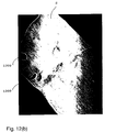
- Fig. 12 shows an example of the generation of an image representing the slope in a surface. With respect to Fig. 12 a left dark field image and a right dark field image are shown as well as the resulting image showing slopes and other 3D-defects on the surface.
- Fig. 12a shows the image of the left dark field.
- a surface S has some spots 1200 thereon, which are e.g. oil spots.
- Fig. 12b shows the image of the right dark field which is substantially identical.
- Fig. 12c illustrates the resulting image after the method described with reference to Fig. 11 has been applied. What can be seen in Fig. 12c is the surface S without the oil spots which are suppressed, and that the 3D-structure of the surface is shown in detail.
- the image shown in Fig. 12c is the output of block 1116 and called a relief image.
- Anomalies in the inspected surface, defect candidates can be detected by simply thresholding the images representing reflectivity, glossiness, slope or color (see block 1120 in Fig. 11). For some classes of defects this will not be the appropriate method for defect detection, e.g. for waves, shallow sloping regions on the surface, or for estimation of surface roughness. For such types of defects it is advantageous to apply statistical measurements, which are tailored to the characteristic features of the considered classes of defects. E.g. the mean value of the slope image formed by block 1116 is calculated within a moving window for detection of shallow sloping regions, or the standard deviation of the slope image formed by block 1116 within a moving window is calculated for estimation of the surface roughness. The size of the moving window is adapted to the size of the considered class of defects. For each pixel, the results of the statistical measurements are compared with a threshold.
- the result of this stage of signal processing are detection images which carry condensed information on local or regional anomalies of the inspected surface, related to the physical properties reflectivity, glossiness, slope and color. It is the advantage of the present invention that this information can be extracted with high reliability, high speed and high spatial resolution.
- the strips need to be inspected in several process stages during the manufacturing to prevent the production of scrap:
- the defect lengths and widths can vary from 0.1 mm up to several meters. Many defects are elongated in the rolling direction so typically the defect length is bigger than its width. Often the critical defects are not flat but have three dimensional shapes due to broken surface or local dents. The defect depths vary from tens of microns to through holes.
- the present invention improves decisively the quality of the measurement signal producing a much more viable basis to automatically identify the critical defects.
- the possibility to directly measure the 3D-characteristics of defects will shorten drastically the start-up periods of the systems being the major hindrance of the current technology. Also the detection performance of small defects is improved due to better measurements.
- the surface was illuminated by light of different colors.
- the present invention is however not limited to these characteristics of the used light beams. Instead of light of different color, light having a different polarization can be used.
- the above described preferred embodiments of the present invention use only one color line scan camera and multiple channels of illumination, and the signal acquisition and processing is based on the idea of photometric stereo.
- the first illumination/observation channel is formed by a first light sensitive sensor device and a light source, wherein the first light sensitive sensor device receives light of a first characteristic reemitted from the surface element, wherein the first light source illuminates the surface element.
- the second illumination/observation channel is formed by a second light sensitive sensor device and the light source, wherein the second light sensitive sensor device receives light of a second characteristic reemitted from the surface element.
- the third illumination/observation channel is in this embodiment formed by a third light sensitive sensor device and the light source, wherein the third light sensor device receives light of a third characteristic reemitted from the surface element.
- this embodiment uses only one light source and three light sensitive sensor devices receiving reemitted light of different characteristics from the surface.
- the first, second and third light sensitive sensor devices are spatially separated from each other.
Landscapes
- Chemical & Material Sciences (AREA)
- Engineering & Computer Science (AREA)
- Health & Medical Sciences (AREA)
- Life Sciences & Earth Sciences (AREA)
- Analytical Chemistry (AREA)
- Biochemistry (AREA)
- General Health & Medical Sciences (AREA)
- General Physics & Mathematics (AREA)
- Immunology (AREA)
- Pathology (AREA)
- Physics & Mathematics (AREA)
- Chemical Kinetics & Catalysis (AREA)
- General Chemical & Material Sciences (AREA)
- Materials Engineering (AREA)
- Mechanical Engineering (AREA)
- Metallurgy (AREA)
- Organic Chemistry (AREA)
- Textile Engineering (AREA)
- Investigating Materials By The Use Of Optical Means Adapted For Particular Applications (AREA)
- Investigating Or Analysing Materials By Optical Means (AREA)
Claims (17)
- Procédé d'inspection automatique de surfaces en mouvement à l'aide d'au moins trois canaux d'éclairage/observation différents, ledit procédé comprenant les étapes consistant à :a) éclairer ladite surface (S) à inspecter dans une condition de champ clair par un premier faisceau lumineux (312) d'une première source de lumière (L1), et recevoir la lumière du premier faisceau lumineux retransmise par ladite surface (S) par un dispositif détecteur photosensible (C), pour obtenir un premier signal (R);b) éclairer ladite surface (S) dans une condition de champ obscur par un second faisceau lumineux (314) et par un troisième faisceau lumineux (316) respectivement d'une seconde et d'une troisième source de lumière (L2, L3), lesdits premier, second et troisième faisceaux lumineux (312, 314, 316) présentant des caractéristiques spectrales différentes, et recevoir respectivement la lumière du second faisceau lumineux et la lumière du troisième faisceau lumineux retransmises par ladite surface (S) par ledit dispositif détecteur photosensible (C), pour obtenir un second signal (G) et un troisième signal (B); etc) dériver desdits premier, second et troisième signaux (R, G, B) au moins deux d'entre les propriétés physiques coefficient de réflexion, brillance et pente de ladite surface (S), où les informations relatives au coefficient de réflexion de ladite surface (S) sont dérivées de la somme des premier, second et troisième signaux, les informations relatives à la brillance de ladite surface (S) sont dérivées du premier signal moins la somme des second et troisième signaux, et les informations relatives à ladite pente de ladite surface (S) sont dérivées de la différence entre le second et le troisième signal.
- Procédé suivant la revendication 1, dans lequel ledit éclairage de ladite surface (S) par lesdits second et troisième faisceaux lumineux (314, 316) est symétrique par rapport au premier faisceau lumineux (312) éclairant ladite surface (S), par rapport à la normale (308) de la surface (S), ou par rapport à la direction d'observation (310).
- Procédé suivant la revendication 1 ou 2, comprenant, avant de dériver les informations relatives au coefficient de réflexion, à la brillance et à la pente de ladite surface (S), les étapes suivantes consistant à :filtrer les premier, second et troisième signaux ; etcalculer les différences normalisées pour chaque signal, afin d'échelonner les signaux de la même manière.
- Procédé suivant l'une quelconque des revendication 1 à 3, comprenant l'étape consistant à détecter des anomalies de la surface (S) en ce qui concerne la propriété physique dérivée.
- Procédé suivant la revendication 4, dans lequel l'étape de détection comprend les étapes suivantes consistant à :calculer des caractéristiques statistiques à partir de la propriété physique dérivée ; etcomparer la propriété physique dérivée avec un seuil.
- Procédé d'inspection automatique de surfaces en mouvement à l'aide d'au moins trois canaux d'éclairage/observation différents, ledit procédé comprenant les étapes consistant à :a) éclairer ladite surface par un faisceau lumineux d'une source de lumière ;b) recevoir la lumière d'une première caractéristique spectrale retransmise par ladite surface dans une condition de champ clair par un premier dispositif détecteur photosensible, pour obtenir un premier signal ;c) recevoir la lumière respectivement d'une seconde et d'une troisième caractéristique spectrale retransmise par ladite surface dans une condition de champ obscur par un second et un troisième dispositif détecteur photosensible, pour obtenir un second et un troisième signal, lesdits premier, second et troisième dispositifs détecteurs photosensibles étant séparés spatialement l'un de l'autre; etd) dériver desdits premier, second et troisième signaux au moins deux d'entre les propriétés physiques coefficient de réflexion, brillance et pente de ladite surface (S), où les informations relatives au coefficient de réflexion de ladite surface (S) sont dérivées de la somme des premier, second et troisième signaux, les informations relatives à la brillance de ladite surface (S) sont dérivées du premier signal moins la somme des second et troisième signaux, et les informations relatives à ladite pente de ladite surface (S) sont dérivées de la différence entre le second et le troisième signal.
- Appareil d'inspection automatique de surfaces en mouvement, comprenantune première source de lumière (L1) éclairant ladite surface (S) par une lumière d'une première caractéristique spectrale dans une condition de champ clair;un dispositif détecteur photosensible (C) recevant la lumière retransmise de la première caractéristique spectrale, pour obtenir un premier signal (R);une seconde source de lumière (L2) éclairant ladite surface (S) par une lumière d'une seconde caractéristique spectrale dans une condition de champ obscur, ladite seconde caractéristique spectrale étant différente de ladite première caractéristique spectrale, ledit dispositif détecteur photosensible (C) recevant la lumière retransmise de la seconde caractéristique spectrale, pour obtenir un second signal (G);une troisième source de lumière (L3) éclairant ladite surface (S) par une lumière d'une troisième caractéristique spectrale dans une condition de champ obscur, ladite troisième caractéristique spectrale étant différente desdites première et seconde caractéristiques spectrales, ledit dispositif détecteur photosensible recevant la lumière retransmise de la troisième caractéristique spectrale, pour obtenir un troisième signal (B); etdes moyens pour dériver au moins deux d'entre les propriétés physiques coefficient de réflexion, brillance et pente de ladite surface (S) desdits premier, second et troisième signaux (R, G, B), lesdits moyens pour dériver comprenant :un moyen (1118) pour additionner les premier, second et troisième signaux, pour fournir un signal représentant le coefficient de réflexion de ladite surface (S) ;un moyen (1114) pour former une différence entre le premier signal et la somme des second et troisième signaux, pour fournir un signal représentant la brillance de ladite surface (S) ; etun moyen (1116) pour former une différence entre le second et le troisième signal, pour fournir un signal représentant la pente de ladite surface (S).
- Appareil suivant la revendication 7, dans lequel lesdites seconde et troisième sources de lumière (L2, L3) sont disposées de manière symétrique par rapport à un faisceau lumineux (312) de ladite première source de lumière (Ll), par rapport à la normale (308) de la surface (S), ou par rapport à la direction d'observation (310).
- Appareil suivant la revendication 7 ou 8, dans lequel lesdits moyens pour dériver une propriété physique comprennent un moyen pour détecter des anomalies de ladite surface (S) sur base de la propriété physique dérivée.
- Appareil suivant l'une quelconque des revendications 7 à 9, dans lequel lesdites première, seconde et troisième sources de lumière sont formées par un ou une pluralité de moyens à fibre optique, chaque moyen à fibre optique présentant au moins une couche de fibres, les moyens à fibre optique et leurs couches de fibres étant disposées de telle sorte que la lumière desdites première, seconde et troisième sources de lumière éclaire ladite surface suivant des angles d'éclairage prédéterminés.
- Appareil suivant l'une quelconque des revendications 7 à 9, dans lequel lesdites première, seconde et troisième sources de lumière sont formées par un moyen à fibre optique (700), ledit moyen à fibre optique comprenant au moins trois couches (806, 808, 810), une première couche (806) fournissant une lumière de la première caractéristique spectrale, une seconde couche (808) fournissant une lumière de la seconde caractéristique spectrale et une troisième couche (810) fournissant une lumière de la troisième caractéristique spectrale, où lesdites première et troisième couches (806, 810) sont inclinées par rapport à la seconde couche (808) de telle sorte que la lumière des première et troisième caractéristiques spectrales éclaire ladite surface suivant des angles d'éclairage prédéterminés.
- Appareil suivant l'une quelconque des revendications 7 à 9, dans lequel lesdites première, seconde et troisième sources de lumière sont formées par un premier et un second moyen à fibre optique, ledit premier moyen à fibre optique comprenant au moins une couche fournissant une lumière de la première caractéristique spectrale, ledit second moyen à fibre optique comprenant au moins deux couches fournissant une lumière de la seconde caractéristique spectrale et de la troisième caractéristique spectrale, où lesdites couches de fibre du second moyen à fibre optique fournissant la lumière des seconde et troisième caractéristiques sont inclinées par rapport à la couche du premier moyen à fibre optique de sorte que la lumière des seconde et troisième caractéristiques spectrales éclaire ladite surface suivant des angles d'éclairage prédéterminés.
- Appareil suivant l'une quelconque des revendications 7 à 9, dans lequel lesdites première, seconde et troisième sources de lumière comprennent des lampes alimentées en CA raccordées à une ligne de fibres au hasard (908a, 908b, 908c), par groupes (900) de trois lampes, où chaque lampe est commandée pour fonctionner selon un déphasage de 120° par rapport aux deux lampes restantes.
- Appareil suivant la revendication 13, dans lequel lesdites lampes alimentées en CA sont des lampes à halogène de métal.
- Appareil suivant l'une quelconque des revendications 7 à 9, dans lequel lesdites première, seconde et troisième sources de lumière sont formées par une lampe, ladite lampe comprenant un moyen diviseur (1002, 1012), pour obtenir au moins trois faisceaux lumineux différents (1010, 1020, 1024) présentant des caractéristiques spectrales différentes.
- Appareil suivant la revendication 15, dans lequel ledit moyen diviseur (1002, 1012) comprend des miroirs et filtres dichroïques pour les différentes caractéristiques spectrales.
- Appareil d'inspection automatique de surfaces en mouvement, comprenantune source de lumière destinée à éclairer ladite surface;un premier dispositif capteur photosensible recevant la lumière d'une première caractéristique spectrale retransmise de ladite surface dans une condition de champ clair, pour obtenir un premier signal;un second dispositif capteur photosensible recevant la lumière d'une seconde caractéristique spectrale retransmise de ladite surface dans une condition de champ obscur, pour obtenir un second signal, ladite seconde caractéristique spectrale étant différente de ladite première caractéristique spectrale;un troisième dispositif capteur photosensible recevant la lumière d'une troisième caractéristique spectrale retransmise de ladite surface dans une condition de champ obscur, pour obtenir un troisième signal, ladite troisième caractéristique spectrale étant différente desdites première et seconde caractéristiques spectrales, lesdits premier, second et troisième dispositifs capteurs photosensibles étant séparés spatialement l'un de l'autre; etdes moyens pour dériver au moins deux d'entre les propriétés physiques coefficient de réflexion, brillance et pente de ladite surface (S) desdits premier, second et troisième signaux (R, G, B), lesdits moyens pour dériver comprenant :un moyen (1118) pour additionner les premier, second et troisième signaux, pour fournir un signal représentant le coefficient de réflexion de ladite surface (S) ;un moyen (1114) pour former une différence entre le premier signal et la somme des second et troisième signaux, pour fournir un signal représentant la brillance de ladite surface (S) ; etun moyen (1116) pour former une différence entre le second et le troisième signal, pour fournir un signal représentant la pente de ladite surface (S).
Priority Applications (7)
| Application Number | Priority Date | Filing Date | Title |
|---|---|---|---|
| DE69703487T DE69703487T2 (de) | 1997-08-22 | 1997-08-22 | Verfahren und Vorrichtung zur automatischen Prüfung bewegter Oberflächen |
| ES97114590T ES2153150T3 (es) | 1997-08-22 | 1997-08-22 | Metodo y aparato para la inspeccion automatica de superficies en movimiento. |
| EP97114590A EP0898163B1 (fr) | 1997-08-22 | 1997-08-22 | Procédé et appareil d'inspection automatique des surfaces en mouvement |
| AT97114590T ATE197503T1 (de) | 1997-08-22 | 1997-08-22 | Verfahren und vorrichtung zur automatischen prüfung bewegter oberflächen |
| JP2000507998A JP3423688B2 (ja) | 1997-08-22 | 1998-07-21 | 移動表面の自動的な検査のための方法及び装置 |
| PCT/EP1998/004560 WO1999010730A1 (fr) | 1997-08-22 | 1998-07-21 | Procede et appareil de controle automatique de surfaces en deplacement |
| US09/136,376 US6166393A (en) | 1997-08-22 | 1998-08-19 | Method and apparatus for automatic inspection of moving surfaces |
Applications Claiming Priority (1)
| Application Number | Priority Date | Filing Date | Title |
|---|---|---|---|
| EP97114590A EP0898163B1 (fr) | 1997-08-22 | 1997-08-22 | Procédé et appareil d'inspection automatique des surfaces en mouvement |
Publications (2)
| Publication Number | Publication Date |
|---|---|
| EP0898163A1 EP0898163A1 (fr) | 1999-02-24 |
| EP0898163B1 true EP0898163B1 (fr) | 2000-11-08 |
Family
ID=8227260
Family Applications (1)
| Application Number | Title | Priority Date | Filing Date |
|---|---|---|---|
| EP97114590A Expired - Lifetime EP0898163B1 (fr) | 1997-08-22 | 1997-08-22 | Procédé et appareil d'inspection automatique des surfaces en mouvement |
Country Status (7)
| Country | Link |
|---|---|
| US (1) | US6166393A (fr) |
| EP (1) | EP0898163B1 (fr) |
| JP (1) | JP3423688B2 (fr) |
| AT (1) | ATE197503T1 (fr) |
| DE (1) | DE69703487T2 (fr) |
| ES (1) | ES2153150T3 (fr) |
| WO (1) | WO1999010730A1 (fr) |
Cited By (3)
| Publication number | Priority date | Publication date | Assignee | Title |
|---|---|---|---|---|
| DE102006038615A1 (de) * | 2006-08-17 | 2008-02-21 | Massen Machine Vision Systems Gmbh | Überwachung der Qualität von gemusterten, insbesondere räumlich gekrümmten Oberflächen |
| EP1654691B1 (fr) * | 2003-07-08 | 2008-11-19 | Stora Enso AB | Procede et dispositif d'analyse de la structure de surface pour papier ou carton |
| DE102010061559A1 (de) * | 2010-12-27 | 2012-06-28 | Dr. Schneider Kunststoffwerke Gmbh | Vorrichtung zum Erkennen von Folienverarbeitungsfehlern |
Families Citing this family (120)
| Publication number | Priority date | Publication date | Assignee | Title |
|---|---|---|---|---|
| FR2781570B1 (fr) * | 1998-07-21 | 2000-08-25 | Lorraine Laminage | Dispositif de detection des defauts superficiels de bandes metalliques en defilement |
| KR100345001B1 (ko) * | 1998-08-27 | 2002-07-19 | 삼성전자 주식회사 | 기판 납땜 검사용 조명 및 광학 장치 |
| JP4110653B2 (ja) | 1999-01-13 | 2008-07-02 | 株式会社ニコン | 表面検査方法及び装置 |
| SE514859C2 (sv) | 1999-01-18 | 2001-05-07 | Mydata Automation Ab | Förfarande och anordning för undersökning av objekt på ett substrat genom att ta bilder av substratet och analysera dessa |
| US7154527B1 (en) * | 1999-02-25 | 2006-12-26 | Visionsense Ltd. | Optical device |
| DE19909534B4 (de) * | 1999-03-04 | 2011-07-07 | BYK-Gardner GmbH, 82538 | Vorrichtung und Verfahren zur Bestimmung der Qualität strukturierter Oberflächen |
| FI111757B (fi) | 1999-05-10 | 2003-09-15 | Metso Automation Oy | Menetelmä ja mittausjärjestely mitata paperin pintaa |
| DE19944216B4 (de) * | 1999-09-15 | 2010-02-04 | Armin Steuer | Prägedruckverfahren und Prägedruckvorrichtung |
| JP4514007B2 (ja) * | 1999-12-28 | 2010-07-28 | 株式会社ブリヂストン | 被検体の外観形状検査方法及び装置 |
| FI20000032A0 (fi) * | 2000-01-07 | 2000-01-07 | Spectra Physics Visiontech Oy | Järjestely ja menetelmä pinnan tarkistamiseksi |
| DE10019486A1 (de) * | 2000-04-19 | 2001-10-31 | Siemens Ag | Anordnung zur Inspektion von Objektoberflächen |
| US6901160B2 (en) | 2000-04-28 | 2005-05-31 | Electro Scientific Industries | Directional lighting and method to distinguish three dimensional information |
| DE10051009A1 (de) * | 2000-10-14 | 2002-05-02 | Nat Rejectors Gmbh | Verfahren zur Erkennung eines Prägebilds einer Münze in einem Münzautomaten |
| DE10063293A1 (de) * | 2000-12-19 | 2002-07-04 | Fraunhofer Ges Forschung | Verfahren und Vorrichtung zur mehrkanaligen Inspektion von Oberflächen im Durchlauf |
| EP1220596A1 (fr) | 2000-12-29 | 2002-07-03 | Icos Vision Systems N.V. | Méthode et appareillage pour mesurer la position d'éléments de contact de composants électroniques |
| US6950547B2 (en) | 2001-02-12 | 2005-09-27 | 3M Innovative Properties Company | Web inspection method and device |
| GB0107900D0 (en) * | 2001-03-29 | 2001-05-23 | Post Office | Improvements in monitoring systems |
| DE10117048C1 (de) * | 2001-04-05 | 2002-08-22 | Fraunhofer Ges Forschung | Verfahren und Vorrichtung zur Detektion von Oberflächendefekten auf Messobjekten |
| DE10122313A1 (de) * | 2001-05-08 | 2002-11-21 | Wolfgang P Weinhold | Verfahren und Vorrichtung zur berührungsfreien Untersuchung eines Gegenstandes, insbesondere hinsichtlich dessen Oberflächengestalt |
| DE10122917A1 (de) * | 2001-05-11 | 2002-11-14 | Byk Gardner Gmbh | Vorrichtung und Verfahren zur Bestimmung der Eigenschaften von reflektierenden Körpern |
| DE10128476C2 (de) * | 2001-06-12 | 2003-06-12 | Siemens Dematic Ag | Optische Sensorvorrichtung zur visuellen Erfassung von Substraten |
| GB2379818A (en) * | 2001-07-25 | 2003-03-19 | Univ Bristol | Automatic surface inspection using plural different radiation sources. |
| US6919965B2 (en) | 2002-03-09 | 2005-07-19 | Kimberly-Clark Worldwide, Inc. | Apparatus and method for making and inspecting pre-fastened articles |
| US6927857B2 (en) * | 2002-03-09 | 2005-08-09 | Kimberly-Clark Worldwide, Inc. | Process for the detection of marked components of a composite article using infrared blockers |
| US6900450B2 (en) | 2002-03-09 | 2005-05-31 | Kimberly-Clark Worldwide, Inc. | Method and apparatus for inferring item position based on multiple data |
| US6885451B2 (en) | 2002-03-09 | 2005-04-26 | Kimberly-Clark Worldwide, Inc. | Infrared detection of composite article components |
| US6888143B2 (en) * | 2002-03-09 | 2005-05-03 | Kimberly-Clark Worldwide, Inc. | Apparatus and method for inspecting pre-fastened articles |
| US7105848B2 (en) * | 2002-04-15 | 2006-09-12 | Wintriss Engineering Corporation | Dual level out-of-focus light source for amplification of defects on a surface |
| US6934029B1 (en) * | 2002-04-22 | 2005-08-23 | Eugene Matzan | Dual laser web defect scanner |
| US7123765B2 (en) * | 2002-07-31 | 2006-10-17 | Kimberly-Clark Worldwide, Inc. | Apparatus and method for inspecting articles |
| DE10300608B4 (de) * | 2003-01-10 | 2004-09-30 | National Rejectors, Inc. Gmbh | Verfahren zur Erkennung eines Prägebildes einer Münze in einem Münzautomaten |
| US20040150815A1 (en) * | 2003-02-05 | 2004-08-05 | Applied Vision Company, Llc | Flaw detection in objects and surfaces |
| US7236625B2 (en) * | 2003-07-28 | 2007-06-26 | The Boeing Company | Systems and method for identifying foreign objects and debris (FOD) and defects during fabrication of a composite structure |
| JP4367085B2 (ja) * | 2003-10-22 | 2009-11-18 | 富士ゼロックス株式会社 | フォトセンサ装置 |
| JP2005172814A (ja) * | 2003-11-19 | 2005-06-30 | Kansai Paint Co Ltd | 反射紫外線測定装置 |
| DE20320094U1 (de) * | 2003-12-23 | 2004-03-11 | Veka Ag | Glanzmessungsvorrichtung |
| BRPI0418285A (pt) | 2003-12-31 | 2007-05-02 | 3M Innovative Properties Co | método e sistema para inspeção automatizada de folhas contìnuas, sistema de controle de conversão, e, meio legìvel por computador |
| KR20060128979A (ko) | 2003-12-31 | 2006-12-14 | 쓰리엠 이노베이티브 프로퍼티즈 컴파니 | 웹 기반 제품의 수율을 최대화하는 방법 및 시스템 |
| JP4045248B2 (ja) * | 2004-03-01 | 2008-02-13 | ジヤトコ株式会社 | 無段変速機用ベルトの検査方法 |
| JP2005283310A (ja) * | 2004-03-29 | 2005-10-13 | Jatco Ltd | リング端面欠陥検査装置 |
| JP2005283309A (ja) * | 2004-03-29 | 2005-10-13 | Jatco Ltd | 金属表面の検査装置 |
| US7623699B2 (en) | 2004-04-19 | 2009-11-24 | 3M Innovative Properties Company | Apparatus and method for the automated marking of defects on webs of material |
| DE102004023739A1 (de) * | 2004-05-12 | 2005-12-15 | Leica Microsystems Semiconductor Gmbh | Messgerät und Verfahren zum Betreiben eines Messgeräts zur optischen Inspektion eines Objekts |
| DE102004037040B4 (de) * | 2004-07-30 | 2013-11-21 | Byk Gardner Gmbh | Vorrichtung zur quantifizierten Bewertung von Oberflächeneigenschaften |
| CA2478757A1 (fr) * | 2004-08-06 | 2006-02-06 | Mario Talbot | Detection du bois bleui et de la pourriture sur le bois d'oeuvre |
| US7471382B2 (en) * | 2004-10-04 | 2008-12-30 | Kla-Tencor Technologies Corporation | Surface inspection system with improved capabilities |
| DE102004058408B4 (de) * | 2004-12-03 | 2013-10-31 | Byk Gardner Gmbh | Vorrichtung zur Bestimmung von Oberflächeneigenschaften |
| US20060145100A1 (en) * | 2005-01-03 | 2006-07-06 | Kimberly-Clark Worldwide, Inc. | System and method for detecting an object on a moving web |
| JP4797593B2 (ja) * | 2005-03-10 | 2011-10-19 | 富士ゼロックス株式会社 | 光沢測定装置及びプログラム |
| JP4826750B2 (ja) * | 2005-04-08 | 2011-11-30 | オムロン株式会社 | 欠陥検査方法およびその方法を用いた欠陥検査装置 |
| KR20080011208A (ko) | 2005-04-21 | 2008-01-31 | 스미토모 덴키 고교 가부시키가이샤 | 초전도 선재의 검사 장치 및 검사 방법 |
| DE102005029901B4 (de) | 2005-06-25 | 2022-10-06 | Modi Modular Digits Gmbh | Vorrichtung und Verfahren zum visuellen Erfassen von flächigen oder räumlichen Objekten |
| EP1752291A1 (fr) * | 2005-08-11 | 2007-02-14 | DeCoSystem S.r.l. | Méthode améliorée et son appareil pour le contrôle de la qualité des matériaux imprimés |
| DE102006009593B4 (de) * | 2005-10-01 | 2008-12-18 | Vistec Semiconductor Systems Gmbh | Vorrichtung zur Aufnahme von mehreren Bildern von scheibenförmigen Objekten |
| US7372556B2 (en) * | 2005-10-31 | 2008-05-13 | The Boeing Company | Apparatus and methods for inspecting a composite structure for inconsistencies |
| WO2007054332A1 (fr) | 2005-11-10 | 2007-05-18 | OBE OHNMACHT & BAUMGäRTNER GMBH & CO. KG | Puce de camera, camera et procede de prise d'image |
| JP4621170B2 (ja) * | 2006-06-05 | 2011-01-26 | 新日本製鐵株式会社 | 金属組織画像観察装置 |
| US7834991B2 (en) | 2006-07-13 | 2010-11-16 | Byk Gardner Gmbh | Determining surface properties with angle offset correction |
| US7369240B1 (en) | 2006-07-20 | 2008-05-06 | Litesentry Corporation | Apparatus and methods for real-time adaptive inspection for glass production |
| US7542821B2 (en) | 2007-07-26 | 2009-06-02 | 3M Innovative Properties Company | Multi-unit process spatial synchronization of image inspection systems |
| US8175739B2 (en) | 2007-07-26 | 2012-05-08 | 3M Innovative Properties Company | Multi-unit process spatial synchronization |
| JP5086734B2 (ja) * | 2007-08-11 | 2012-11-28 | 花王株式会社 | パレット検査装置 |
| FI121151B (fi) | 2007-11-22 | 2010-07-30 | Valtion Teknillinen | Menetelmä ja laitteisto liikkuvan pinnan topografian ja optisten ominaisuuksien määrittämiseksi |
| DE102008000774A1 (de) * | 2008-03-19 | 2009-09-24 | Voith Patent Gmbh | Optisches Verfahren und Messvorrichtung für eine Fasern beinhaltende Bahn |
| EP2144052A1 (fr) * | 2008-07-11 | 2010-01-13 | Dr. Schenk GmbH Industriemesstechnik | Procédé et dispositif de détection et de classification de défauts |
| WO2010006895A1 (fr) * | 2008-07-16 | 2010-01-21 | Siemens Aktiengesellschaft | Procédé de conduite d'un dispositif de traitement d'un feuillard métallique et installation de traitement d'un feuillard métallique |
| DE102008044991B4 (de) * | 2008-08-29 | 2011-11-10 | In-Situ Gmbh | Verfahren und Vorrichtung zur dreidimensionalen Erfassung von Objektoberflächen |
| US7797133B2 (en) | 2008-09-10 | 2010-09-14 | 3M Innovative Properties Company | Multi-roller registered repeat defect detection of a web process line |
| US8502180B2 (en) * | 2009-01-26 | 2013-08-06 | Centre De Recherche Industrielle Du Quebec | Apparatus and method having dual sensor unit with first and second sensing fields crossed one another for scanning the surface of a moving article |
| US9109330B2 (en) * | 2009-03-09 | 2015-08-18 | Honeywell International Inc. | Apparatus and method for measuring properties of unstabilized moving sheets |
| NO336577B1 (no) * | 2009-07-08 | 2015-09-28 | Sapa As | Fremgangsmåte og apparatur for inspeksjon av overflater |
| US20110035041A1 (en) * | 2009-08-06 | 2011-02-10 | Habakus Stephen J | Systems and methods for feed control of rolled stock raw materials |
| MX2012014516A (es) | 2010-06-16 | 2013-01-29 | Forensic Technology Wai Inc | Adquisicion de imagenes topograficas en 3d de marcas de herramientas utilizando un metodo estereo fotometrico no lineal. |
| DE102010060852B4 (de) | 2010-11-29 | 2013-11-21 | Breitmeier Messtechnik Gmbh | Vorrichtung und Verfahren zur Erfassung einer Oberflächenstruktur einer Oberfläche eines Werkstücks |
| FR2977939B1 (fr) | 2011-07-11 | 2013-08-09 | Edixia | Procede d'acquisition de plusieurs images d'un meme objet a l'aide d'une seule camera lineaire |
| JP5882730B2 (ja) | 2011-12-28 | 2016-03-09 | 株式会社ブリヂストン | 外観検査装置及び外観検査方法 |
| CA2780202C (fr) | 2012-06-19 | 2014-11-18 | Centre De Recherche Industrielle Du Quebec | Procede et systeme pour detecter la qualite de l'ecorcage a la surface d'un billot de bois |
| AT513126B1 (de) * | 2012-08-01 | 2014-02-15 | Ait Austrian Inst Technology | Co-Occurrence Matrix |
| DE102012015579A1 (de) * | 2012-08-08 | 2014-02-13 | Premium Aerotec Gmbh | Oberflächenschutzverfahren für Bauteile aus Aluminium bzw. Aluminiumlegierungen mit einem Nachweis einer unzulässigen Überhitzung |
| KR101480906B1 (ko) * | 2012-11-15 | 2015-01-12 | 주식회사 포스코 | 잔류 스케일 측정 장치 및 방법 |
| CN110455816A (zh) * | 2012-12-10 | 2019-11-15 | 乌斯特技术股份公司 | 用于光学检查移动纺织材料的设备 |
| US9581554B2 (en) * | 2013-05-30 | 2017-02-28 | Seagate Technology Llc | Photon emitter array |
| JP5949690B2 (ja) * | 2013-07-25 | 2016-07-13 | Jfeスチール株式会社 | 評価方法及び評価装置 |
| WO2015027014A1 (fr) * | 2013-08-21 | 2015-02-26 | Severstal Dearborn, Llc | Procédé de mesure des caractéristiques d'une tôle d'acier galvanisé-recuit revêtue par immersion en bain chaud |
| DE102013221334A1 (de) | 2013-10-21 | 2015-04-23 | Volkswagen Aktiengesellschaft | Verfahren und Messvorrichtung zum Bewerten von Strukturunterschieden einer reflektierenden Oberfläche |
| US10180401B2 (en) | 2013-12-27 | 2019-01-15 | Jfe Steel Corporation | Surface defect detecting method and surface defect detecting apparatus |
| CN104897679A (zh) * | 2014-03-05 | 2015-09-09 | 鞍钢股份有限公司 | 一种钢板表面缺陷的检查方法 |
| GB2526866A (en) * | 2014-06-05 | 2015-12-09 | Univ Bristol | Apparatus for and method of inspecting surface topography of a moving object |
| JP6290720B2 (ja) * | 2014-06-09 | 2018-03-07 | 株式会社キーエンス | 検査装置、検査方法およびプログラム |
| EP2966593A1 (fr) | 2014-07-09 | 2016-01-13 | Sick Ag | Système de saisie d'images destiné à détecter un objet |
| AT516824A1 (de) * | 2015-01-23 | 2016-08-15 | Ait Austrian Inst Technology | Verfahren und Vorrichtung zur Prüfung von OVI-Merkmalen |
| US9970750B2 (en) * | 2015-05-29 | 2018-05-15 | Nippon Steel & Sumitomo Metal Corporation | Shape inspection apparatus for metallic body and shape inspection method for metallic body |
| CN107003115B (zh) * | 2015-06-05 | 2019-08-09 | 日本制铁株式会社 | 金属体的形状检查装置和金属体的形状检查方法 |
| JP6447637B2 (ja) * | 2015-06-25 | 2019-01-09 | Jfeスチール株式会社 | 表面欠陥検出装置、表面欠陥検出方法、及び鋼材の製造方法 |
| KR20180009791A (ko) * | 2015-06-25 | 2018-01-29 | 제이에프이 스틸 가부시키가이샤 | 표면 결함 검출 방법, 표면 결함 검출 장치 및, 강재의 제조 방법 |
| EP3315951A4 (fr) * | 2015-06-25 | 2018-12-26 | JFE Steel Corporation | Appareil de détection d'un défaut de surface et procédé de détection d'un défaut de surface |
| JP6394514B2 (ja) * | 2015-06-25 | 2018-09-26 | Jfeスチール株式会社 | 表面欠陥検出方法、表面欠陥検出装置、及び鋼材の製造方法 |
| US11493454B2 (en) | 2015-11-13 | 2022-11-08 | Cognex Corporation | System and method for detecting defects on a specular surface with a vision system |
| US10495581B2 (en) | 2016-01-08 | 2019-12-03 | SCREEN Holdings Co., Ltd. | Defect detection device and defect detection method |
| EP3252457A4 (fr) * | 2016-04-08 | 2019-01-16 | Nippon Steel & Sumitomo Metal Corporation | Dispositif de surveillance d'état de surface de corps métallique et procédé de surveillance d'état de surface de corps métallique |
| EP3465171A1 (fr) * | 2016-05-30 | 2019-04-10 | Bobst Mex Sa | Système d'inspection de surface et procédé d'inspection |
| JP6893219B2 (ja) * | 2016-05-30 | 2021-06-23 | ボブスト メックス ソシエテ アノニムBobst Mex SA | 表面検査システム及び表面検査方法 |
| CN109196337B (zh) * | 2016-05-30 | 2021-12-07 | 鲍勃斯脱梅克斯股份有限公司 | 一种图像捕获系统和一种用于确定片材元件上压花结构的位置的方法 |
| JP6769182B2 (ja) * | 2016-09-01 | 2020-10-14 | 日本製鉄株式会社 | 鋼材の表面検査装置及び表面検査方法 |
| DE102016012371A1 (de) * | 2016-10-15 | 2018-04-19 | INPRO Innovationsgesellschaft für fortgeschrittene Produktionssysteme in der Fahrzeugindustrie mbH | Verfahren und Anlage zum Ermitteln der Defektfläche mindestens einer Fehlstelle auf mindestens einer Funktionsoberfläche eines Bauteils oder Prüfkörpers |
| DE102017206058A1 (de) * | 2017-04-10 | 2018-10-11 | BSH Hausgeräte GmbH | Bestimmen eines Verschmutzungsgrads in einem Garraum |
| JP6863206B2 (ja) * | 2017-09-28 | 2021-04-21 | 日本製鉄株式会社 | 鋳片分析装置、鋳片分析方法及びプログラム |
| EP3722745B1 (fr) * | 2017-12-08 | 2023-09-06 | Nippon Steel Corporation | Dispositif d'inspection de forme et procédé d'inspection de forme |
| JP7077635B2 (ja) * | 2018-01-26 | 2022-05-31 | 王子ホールディングス株式会社 | シート状物の欠陥検査装置及び製造方法 |
| JP7087687B2 (ja) * | 2018-06-01 | 2022-06-21 | 株式会社サタケ | 穀物の光沢測定装置 |
| DE102018006760A1 (de) * | 2018-08-27 | 2020-02-27 | Mühlbauer Gmbh & Co. Kg | Inspektion beim Übertragen elektronischer Bauteile von einem ersten zu einem zweiten Träger |
| WO2020150749A1 (fr) * | 2019-01-18 | 2020-07-23 | Essenlix Corporation | Système d'éclairage multimode |
| JP7138194B2 (ja) * | 2019-01-25 | 2022-09-15 | タカノ株式会社 | 画像検査装置 |
| JPWO2020158340A1 (ja) * | 2019-02-01 | 2021-11-18 | パナソニックIpマネジメント株式会社 | 検査装置、及び、検査方法 |
| JP7307815B2 (ja) * | 2019-04-25 | 2023-07-12 | スペイラ ゲゼルシャフト ミット ベシュレンクテル ハフツング | 色測定を含むアルミニウム合金製の平らな製品の表面処理 |
| EP3754324B1 (fr) * | 2019-06-19 | 2023-11-29 | Fraunhofer-Gesellschaft zur Förderung der angewandten Forschung e.V. | Procédé et dispositif de classification d'une contamination particulaire sur une surface |
| EP3761017A1 (fr) | 2019-07-05 | 2021-01-06 | Aleris Rolled Products Germany GmbH | Procédé et appareil d'inspection thermographique des surfaces d'un article mobile à bande métallique laminée à chaud |
| US11282187B2 (en) * | 2019-08-19 | 2022-03-22 | Ricoh Company, Ltd. | Inspection system, inspection apparatus, and method using multiple angle illumination |
| EP4095518A4 (fr) * | 2020-01-20 | 2023-02-08 | JFE Steel Corporation | Dispositif d'inspection de surface, procédé d'inspection de surface, procédé de fabrication de matériau d'acier, procédé de gestion de qualité de matériau d'acier et équipement de fabrication de matériau d'acier |
| CN114689604A (zh) * | 2020-12-29 | 2022-07-01 | 致茂电子(苏州)有限公司 | 具有光滑表面的待测物于光学检测上的影像处理方法及其检测系统 |
Family Cites Families (12)
| Publication number | Priority date | Publication date | Assignee | Title |
|---|---|---|---|---|
| US4806776A (en) * | 1980-03-10 | 1989-02-21 | Kley Victor B | Electrical illumination and detecting apparatus |
| JPS5952735A (ja) * | 1982-09-20 | 1984-03-27 | Kawasaki Steel Corp | 熱間鋼片の表面欠陥検出方法 |
| DE3242447C2 (de) * | 1982-11-16 | 1986-01-23 | Sophokles 8062 Markt Indersdorf Papaioannou | Photoelektrische Kontrollvorrichtung zur Qualitätskontrolle einer bewegten Materialbahn |
| US4595289A (en) * | 1984-01-25 | 1986-06-17 | At&T Bell Laboratories | Inspection system utilizing dark-field illumination |
| JPS61176825A (ja) * | 1985-01-31 | 1986-08-08 | Dainippon Printing Co Ltd | 光センサヘツド |
| US5039868A (en) * | 1988-11-24 | 1991-08-13 | Omron Corporation | Method of and apparatus for inspecting printed circuit boards and the like |
| AU8071791A (en) * | 1990-06-22 | 1992-01-23 | Alcan International Limited | Illumination system for high speed surface inspection of rolled aluminum sheet |
| US5248876A (en) * | 1992-04-21 | 1993-09-28 | International Business Machines Corporation | Tandem linear scanning confocal imaging system with focal volumes at different heights |
| JPH0658731A (ja) * | 1992-06-11 | 1994-03-04 | Fujitsu Ltd | パターン検査装置 |
| WO1994018643A1 (fr) * | 1993-02-02 | 1994-08-18 | Golden Aluminum Company | Procede et appareil de mise en image de surfaces |
| DE19511534C2 (de) * | 1995-03-29 | 1998-01-22 | Fraunhofer Ges Forschung | Verfahren und Vorrichtung zur Erfassung von 3D-Fehlstellen bei der automatischen Inspektion von Oberflächen mit Hilfe farbtüchtiger Bildauswertungssysteme |
| US5982493A (en) * | 1998-06-02 | 1999-11-09 | Motorola, Inc. | Apparatus and method for acquiring multiple images |
-
1997
- 1997-08-22 DE DE69703487T patent/DE69703487T2/de not_active Expired - Lifetime
- 1997-08-22 AT AT97114590T patent/ATE197503T1/de not_active IP Right Cessation
- 1997-08-22 EP EP97114590A patent/EP0898163B1/fr not_active Expired - Lifetime
- 1997-08-22 ES ES97114590T patent/ES2153150T3/es not_active Expired - Lifetime
-
1998
- 1998-07-21 WO PCT/EP1998/004560 patent/WO1999010730A1/fr active Search and Examination
- 1998-07-21 JP JP2000507998A patent/JP3423688B2/ja not_active Expired - Fee Related
- 1998-08-19 US US09/136,376 patent/US6166393A/en not_active Expired - Fee Related
Cited By (3)
| Publication number | Priority date | Publication date | Assignee | Title |
|---|---|---|---|---|
| EP1654691B1 (fr) * | 2003-07-08 | 2008-11-19 | Stora Enso AB | Procede et dispositif d'analyse de la structure de surface pour papier ou carton |
| DE102006038615A1 (de) * | 2006-08-17 | 2008-02-21 | Massen Machine Vision Systems Gmbh | Überwachung der Qualität von gemusterten, insbesondere räumlich gekrümmten Oberflächen |
| DE102010061559A1 (de) * | 2010-12-27 | 2012-06-28 | Dr. Schneider Kunststoffwerke Gmbh | Vorrichtung zum Erkennen von Folienverarbeitungsfehlern |
Also Published As
| Publication number | Publication date |
|---|---|
| WO1999010730A1 (fr) | 1999-03-04 |
| DE69703487T2 (de) | 2001-06-13 |
| DE69703487D1 (de) | 2000-12-14 |
| JP3423688B2 (ja) | 2003-07-07 |
| EP0898163A1 (fr) | 1999-02-24 |
| JP2001514386A (ja) | 2001-09-11 |
| ES2153150T3 (es) | 2001-02-16 |
| ATE197503T1 (de) | 2000-11-11 |
| US6166393A (en) | 2000-12-26 |
Similar Documents
| Publication | Publication Date | Title |
|---|---|---|
| EP0898163B1 (fr) | Procédé et appareil d'inspection automatique des surfaces en mouvement | |
| EP1943502B1 (fr) | Appareil et procedes de verification de la presence de defauts dans une structure composite | |
| US6327374B1 (en) | Arrangement and method for inspection of surface quality | |
| US5887077A (en) | Method for the recognition and evaluation of defects in reflective surface coatings | |
| US6064478A (en) | Method of and apparatus for automatic detection of three-dimensional defects in moving surfaces by means of color vision systems | |
| CA2151344C (fr) | Systeme et methode d'inspection de lentilles de contact | |
| JP3312849B2 (ja) | 物体表面の欠陥検出方法 | |
| US7970202B2 (en) | Method and arrangement for detecting surface and structural defects of a long moving product | |
| US20070286471A1 (en) | Auto Distinction System And Auto Distinction Method | |
| EP3364173A1 (fr) | Dispositif et procédé d'inspection de défaut de surface dans une plaque d'acier | |
| CN104508423A (zh) | 用于被检查对象的表面的检查的方法和装置 | |
| US20130215261A1 (en) | Method For Detecting Defects In Glassware Articles, And Installation For Implementing Said Method | |
| US20180017503A1 (en) | Surface defect inspecting device and method for hot-dip coated steel sheets | |
| WO1994018643A1 (fr) | Procede et appareil de mise en image de surfaces | |
| EP1277042B1 (fr) | Eclairage directionnel et procede de distinction de trois informations dimensionnelles | |
| EP0539499B1 (fr) | Procede et appareil pour mesurer la frequence de frisure d'un tissu | |
| WO2022030083A1 (fr) | Dispositif d'inspection de surface de bande métallique, procédé d'inspection de surface et procédé de fabrication | |
| JPH07218451A (ja) | 光学式鋼板表面検査装置 | |
| EP2452181A1 (fr) | Procédé et appareil pour inspection de surfaces | |
| Adameck et al. | Three color selective stereo gradient method for fast topography recognition of metallic surfaces | |
| JP7136064B2 (ja) | 被検査体の表面検査装置および被検査体の表面検査方法 | |
| CN105874318B (zh) | 一种测量谷物光泽的方法及装置 | |
| CN116087209A (zh) | 一种金丝键合工艺的外观检测方法及系统 | |
| CN114813744A (zh) | 多工位图像综合复判缺陷检测方法 |
Legal Events
| Date | Code | Title | Description |
|---|---|---|---|
| PUAI | Public reference made under article 153(3) epc to a published international application that has entered the european phase |
Free format text: ORIGINAL CODE: 0009012 |
|
| 17P | Request for examination filed |
Effective date: 19980625 |
|
| AK | Designated contracting states |
Kind code of ref document: A1 Designated state(s): AT BE CH DE ES FI FR GB IE IT LI LU SE |
|
| AKX | Designation fees paid |
Free format text: AT BE CH DE ES FI FR GB IE IT LI LU SE |
|
| GRAG | Despatch of communication of intention to grant |
Free format text: ORIGINAL CODE: EPIDOS AGRA |
|
| GRAG | Despatch of communication of intention to grant |
Free format text: ORIGINAL CODE: EPIDOS AGRA |
|
| GRAG | Despatch of communication of intention to grant |
Free format text: ORIGINAL CODE: EPIDOS AGRA |
|
| GRAH | Despatch of communication of intention to grant a patent |
Free format text: ORIGINAL CODE: EPIDOS IGRA |
|
| 17Q | First examination report despatched |
Effective date: 19981217 |
|
| GRAH | Despatch of communication of intention to grant a patent |
Free format text: ORIGINAL CODE: EPIDOS IGRA |
|
| GRAA | (expected) grant |
Free format text: ORIGINAL CODE: 0009210 |
|
| ITF | It: translation for a ep patent filed |
Owner name: JACOBACCI & PERANI S.P.A. |
|
| AK | Designated contracting states |
Kind code of ref document: B1 Designated state(s): AT BE CH DE ES FI FR GB IE IT LI LU SE |
|
| REF | Corresponds to: |
Ref document number: 197503 Country of ref document: AT Date of ref document: 20001111 Kind code of ref document: T |
|
| REG | Reference to a national code |
Ref country code: CH Ref legal event code: EP |
|
| ET | Fr: translation filed | ||
| REG | Reference to a national code |
Ref country code: IE Ref legal event code: FG4D |
|
| REF | Corresponds to: |
Ref document number: 69703487 Country of ref document: DE Date of ref document: 20001214 |
|
| REG | Reference to a national code |
Ref country code: ES Ref legal event code: FG2A Ref document number: 2153150 Country of ref document: ES Kind code of ref document: T3 |
|
| REG | Reference to a national code |
Ref country code: CH Ref legal event code: NV Representative=s name: BOVARD AG PATENTANWAELTE |
|
| PLBE | No opposition filed within time limit |
Free format text: ORIGINAL CODE: 0009261 |
|
| STAA | Information on the status of an ep patent application or granted ep patent |
Free format text: STATUS: NO OPPOSITION FILED WITHIN TIME LIMIT |
|
| 26N | No opposition filed | ||
| REG | Reference to a national code |
Ref country code: GB Ref legal event code: IF02 |
|
| REG | Reference to a national code |
Ref country code: CH Ref legal event code: PFA Owner name: SPECTRA-PHYSICS VISIONTECH OY Free format text: FRAUNHOFER-GESELLSCHAFT ZUR FOERDERUNG DER ANGEWANDTEN FORSCHUNG E.V.#LEONRODSTRASSE 54#80636 MUENCHEN (DE) $ SPECTRA-PHYSICS VISIONTECH OY#TEKNOLOGIANTIE 2, P.O. BOX 80#90571 OULU (FI) $ VTT ELECTRONICS#KAITOVAEYLAE 1, P.O. BOX 1100#90571 OULU (FI) -TRANSFER TO- SPECTRA-PHYSICS VISIONTECH OY#TEKNOLOGIANTIE 2, P.O. BOX 80#90571 OULU (FI) $ VTT ELECTRONICS#KAITOVAEYLAE 1, P.O. BOX 1100#90571 OULU (FI) $ FRAUNHOFER-GESELLSCHAFT ZUR FOERDERUNG DER ANGEWANDTEN FORSCHUNG E.V.#HANSASTRASSE 27 C#80686 MUENCHEN (DE) |
|
| PGFP | Annual fee paid to national office [announced via postgrant information from national office to epo] |
Ref country code: IE Payment date: 20060824 Year of fee payment: 10 |
|
| PGFP | Annual fee paid to national office [announced via postgrant information from national office to epo] |
Ref country code: FI Payment date: 20060825 Year of fee payment: 10 |
|
| PGFP | Annual fee paid to national office [announced via postgrant information from national office to epo] |
Ref country code: BE Payment date: 20060828 Year of fee payment: 10 Ref country code: AT Payment date: 20060828 Year of fee payment: 10 |
|
| PGFP | Annual fee paid to national office [announced via postgrant information from national office to epo] |
Ref country code: LU Payment date: 20060829 Year of fee payment: 10 Ref country code: CH Payment date: 20060829 Year of fee payment: 10 |
|
| PGFP | Annual fee paid to national office [announced via postgrant information from national office to epo] |
Ref country code: ES Payment date: 20060831 Year of fee payment: 10 |
|
| PGFP | Annual fee paid to national office [announced via postgrant information from national office to epo] |
Ref country code: SE Payment date: 20060829 Year of fee payment: 10 |
|
| BERE | Be: lapsed |
Owner name: *VTT ELECTRONICS Effective date: 20070831 Owner name: *SPECTRA-PHYSICS VISIONTECH OY Effective date: 20070831 Owner name: *FRAUNHOFER-GESELLSCHAFT ZUR FORDERUNG DER ANGEWAN Effective date: 20070831 |
|
| EUG | Se: european patent has lapsed | ||
| REG | Reference to a national code |
Ref country code: CH Ref legal event code: PL |
|
| PG25 | Lapsed in a contracting state [announced via postgrant information from national office to epo] |
Ref country code: SE Free format text: LAPSE BECAUSE OF NON-PAYMENT OF DUE FEES Effective date: 20070823 Ref country code: LI Free format text: LAPSE BECAUSE OF NON-PAYMENT OF DUE FEES Effective date: 20070831 Ref country code: CH Free format text: LAPSE BECAUSE OF NON-PAYMENT OF DUE FEES Effective date: 20070831 |
|
| PG25 | Lapsed in a contracting state [announced via postgrant information from national office to epo] |
Ref country code: FI Free format text: LAPSE BECAUSE OF NON-PAYMENT OF DUE FEES Effective date: 20070822 |
|
| REG | Reference to a national code |
Ref country code: IE Ref legal event code: MM4A |
|
| PG25 | Lapsed in a contracting state [announced via postgrant information from national office to epo] |
Ref country code: AT Free format text: LAPSE BECAUSE OF NON-PAYMENT OF DUE FEES Effective date: 20070822 |
|
| PG25 | Lapsed in a contracting state [announced via postgrant information from national office to epo] |
Ref country code: BE Free format text: LAPSE BECAUSE OF NON-PAYMENT OF DUE FEES Effective date: 20070831 |
|
| PG25 | Lapsed in a contracting state [announced via postgrant information from national office to epo] |
Ref country code: IE Free format text: LAPSE BECAUSE OF NON-PAYMENT OF DUE FEES Effective date: 20070822 |
|
| REG | Reference to a national code |
Ref country code: ES Ref legal event code: FD2A Effective date: 20070823 |
|
| PGFP | Annual fee paid to national office [announced via postgrant information from national office to epo] |
Ref country code: IT Payment date: 20080826 Year of fee payment: 12 Ref country code: FR Payment date: 20080818 Year of fee payment: 12 |
|
| PGFP | Annual fee paid to national office [announced via postgrant information from national office to epo] |
Ref country code: GB Payment date: 20080822 Year of fee payment: 12 |
|
| PG25 | Lapsed in a contracting state [announced via postgrant information from national office to epo] |
Ref country code: ES Free format text: LAPSE BECAUSE OF NON-PAYMENT OF DUE FEES Effective date: 20070823 |
|
| PG25 | Lapsed in a contracting state [announced via postgrant information from national office to epo] |
Ref country code: LU Free format text: LAPSE BECAUSE OF NON-PAYMENT OF DUE FEES Effective date: 20070822 |
|
| GBPC | Gb: european patent ceased through non-payment of renewal fee |
Effective date: 20090822 |
|
| REG | Reference to a national code |
Ref country code: FR Ref legal event code: ST Effective date: 20100430 |
|
| PG25 | Lapsed in a contracting state [announced via postgrant information from national office to epo] |
Ref country code: FR Free format text: LAPSE BECAUSE OF NON-PAYMENT OF DUE FEES Effective date: 20090831 |
|
| PG25 | Lapsed in a contracting state [announced via postgrant information from national office to epo] |
Ref country code: GB Free format text: LAPSE BECAUSE OF NON-PAYMENT OF DUE FEES Effective date: 20090822 |
|
| PG25 | Lapsed in a contracting state [announced via postgrant information from national office to epo] |
Ref country code: IT Free format text: LAPSE BECAUSE OF NON-PAYMENT OF DUE FEES Effective date: 20090822 |
|
| PGFP | Annual fee paid to national office [announced via postgrant information from national office to epo] |
Ref country code: DE Payment date: 20150820 Year of fee payment: 19 |
|
| REG | Reference to a national code |
Ref country code: DE Ref legal event code: R119 Ref document number: 69703487 Country of ref document: DE |
|
| PG25 | Lapsed in a contracting state [announced via postgrant information from national office to epo] |
Ref country code: DE Free format text: LAPSE BECAUSE OF NON-PAYMENT OF DUE FEES Effective date: 20170301 |