EP0897365B1 - Hubschraubertaumelscheibe mit integrierter pumpe - Google Patents
Hubschraubertaumelscheibe mit integrierter pumpe Download PDFInfo
- Publication number
- EP0897365B1 EP0897365B1 EP97922944A EP97922944A EP0897365B1 EP 0897365 B1 EP0897365 B1 EP 0897365B1 EP 97922944 A EP97922944 A EP 97922944A EP 97922944 A EP97922944 A EP 97922944A EP 0897365 B1 EP0897365 B1 EP 0897365B1
- Authority
- EP
- European Patent Office
- Prior art keywords
- helicopter according
- swash plate
- pump
- cam track
- cylinders
- Prior art date
- Legal status (The legal status is an assumption and is not a legal conclusion. Google has not performed a legal analysis and makes no representation as to the accuracy of the status listed.)
- Expired - Lifetime
Links
- 230000000694 effects Effects 0.000 claims description 3
- 238000005096 rolling process Methods 0.000 claims description 3
- 238000005086 pumping Methods 0.000 claims description 2
- 230000001788 irregular Effects 0.000 claims 1
- 238000010276 construction Methods 0.000 description 3
- 238000005461 lubrication Methods 0.000 description 2
- 239000003921 oil Substances 0.000 description 2
- 230000001360 synchronised effect Effects 0.000 description 2
- 238000009966 trimming Methods 0.000 description 2
- 239000006096 absorbing agent Substances 0.000 description 1
- 230000033228 biological regulation Effects 0.000 description 1
- 230000005540 biological transmission Effects 0.000 description 1
- 230000000903 blocking effect Effects 0.000 description 1
- 125000004122 cyclic group Chemical group 0.000 description 1
- 238000013016 damping Methods 0.000 description 1
- 230000007423 decrease Effects 0.000 description 1
- 210000003746 feather Anatomy 0.000 description 1
- 239000010720 hydraulic oil Substances 0.000 description 1
- 238000009434 installation Methods 0.000 description 1
- 230000002093 peripheral effect Effects 0.000 description 1
Images

Classifications
-
- B—PERFORMING OPERATIONS; TRANSPORTING
- B64—AIRCRAFT; AVIATION; COSMONAUTICS
- B64C—AEROPLANES; HELICOPTERS
- B64C27/00—Rotorcraft; Rotors peculiar thereto
- B64C27/54—Mechanisms for controlling blade adjustment or movement relative to rotor head, e.g. lag-lead movement
- B64C27/58—Transmitting means, e.g. interrelated with initiating means or means acting on blades
- B64C27/59—Transmitting means, e.g. interrelated with initiating means or means acting on blades mechanical
- B64C27/605—Transmitting means, e.g. interrelated with initiating means or means acting on blades mechanical including swash plate, spider or cam mechanisms
Definitions
- the invention relates to a helicopter with the Features according to the preamble of claim 1.
- the centerpiece of a helicopter is its main rotor. It ensures that with its two and more rotor blades hinged to a rotor head and pivotable about its longitudinal axis are stored, not only for buoyancy, but also for the propulsion.
- the propulsion of the aircraft is due to inclination of the thrust vector based on the cyclic, d. H. a speed synchronous alternating control and the resulting following slight tilting of the rotor blade tip plane generated from the horizontal state.
- the helicopter pilot oversteers the rotor blades a swashplate that includes the main rotor mast.
- she consists of a stationary part, which has a so-called Scissors non-rotatable, but axially displaceable and for Rotor mast swiveling in all directions on the housing of one Gearbox is attached, and a rotatable part that over Radial and axial bearings can be rotated relative to the stationary part is stored.
- the rotatable part moves with the stationary part in the axial direction and also makes the tilting movements with. He is on another pair of scissors Rotor head attached.
- the movement of the swashplate is controlled by a lever mechanism on the rotor blade flow in front or behind the leaf connections lying on the leaf receptacles, in such a way that the setting angle of the Rotor blade enlarged with the swash plate approaching or reduced.
- the helicopter pilot adjusts for the flight maneuvers the swashplate via another lever mechanism.
- hydraulic servomotors arranged, on the one hand the Control easier and secondly a superimposed Enable regulation, the occurring rotor blade vibrations counteracts.
- Servomotors also serve this purpose and active hydraulic dampers that rotate in the System are arranged and individual rotor blades individually head for.
- One or more gas turbines drive the main rotor via a gearbox and a main rotor mast in the housing of the gear is rotatably mounted and on which the Rotor head is attached.
- the hydraulic motors and active steamers need a hydraulic output of approx. 1% of the main rotor output. Separate pumps are used for this. This have a considerable weight and claim significant Installation space. Furthermore, the supply lines to the consumers often long and complex, especially if it is from lead a stationary part to a rotating part.
- the invention has for its object the hydraulic Motors and active steamers with the required To provide performance, to save weight, the construction effort reduce and improve efficiency.
- the position of the pump is characterized in that the Construction volume of the swash plate is not or at most only very much is slightly enlarged. Furthermore, the connection channels to consumers both in the stationary part of the Helicopter as well as in the rotating system very short. If the pump is only used to supply consumers in the rotating system used, the cylinders are conveniently arranged in the rotatable part of the swash plate, because this means complex pressure oil connections between the parts rotating relative to each other avoided become.
- the pistons expediently have spherical end faces, with which they slide on the cam tracks, so you can follow them better.
- Rolling elements in the form of Balls or rollers as well as roller bearings can usefully reduce friction and wear.
- cam track especially the running surface of the pistons, is protected against dirt and their lubrication ensured if the cam track between after externally sealed radial or axial bearings is.
- An annular channel connects on the pressure side of the pump the exhaust ports of the individual cylinders. But it can also several ring channels can be provided in groups summarize the cylinders. The ring channels can be used simultaneously serve as collection rooms for the pressure oil and if necessary be designed as absorber rooms to absorb vibrations dampen and smooth the volume flow.
- the pump may not Do not block the rotor. It is therefore according to an embodiment provided that the disc or the ring with the Cam track using shear pins or a similar predetermined breaking element is connected to the swash plate.
- the disc or the ring with the Cam track using shear pins or a similar predetermined breaking element is connected to the swash plate.
- Rotor blades each articulated via a rotor blade holder 2 are. This has a swivel lever 3 with which it can be used the rotor blade is pivotable about its longitudinal axis.
- the pivot lever 3 engages via a joint hydraulic actuator 4 at that with its free end on an arm 5 of a rotatable part 9 of a swash plate is articulated.
- the rotatable part 9 is opposite one stationary part 11 of the swash plate by axial and Radial bearing 13 mounted. Seals 12 seal the area the thrust and radial bearings to the outside.
- a so-called scissors 7 holds the stationary part 11 the swash plate fixed to a housing 8 of a transmission, but it allows that the swash plate axially displaced and is pivotable in all directions to the main rotor mast 22.
- the rotatable part 9 of the Rotor head 1 taken for rotation.
- the swashplate is a multi-cylinder radial piston pump arranged.
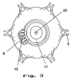
- Your power parts, piston 15 and cylinder 20, are located in the rotatable part 9 and close working spaces 19th on.
- Springs 16 press the pistons 15 against a cam track 23 on a ring 14 which is connected to the stationary part 11 is rotatably connected.
- the cams of the cam track 23 actuate the pistons 15, which reduces the work space 19 and enlarge and a pump effect arises.
- tappets 21 in which balls 24 are stored. These reduce the Friction and wear. They also ensure that the pistons 15 with their tappets 21 having a cam track 23 can follow many cams well.
- the hydraulic oil is supplied via intake channels 17 and via pressure channels 18 to the hydraulic actuators 4 funded.
- the channels 17, 18 open into not shown Ring channels, both on the suction side as well on the print side designed as collection and repayment rooms can be.
- Valves, not shown, which are appropriate are designed as leaf spring valves, control the suction side and the pressure side of the pump.
- the ring 14 shown with the cam track 23 is integrally formed with the stationary part 11.
- the ring 14 In order to prevent the rotor from being blocked by the pump can, it is appropriate to the ring 14 as a separate component and with shear pins or similar predetermined breaking elements non-rotatably connected to the stationary part 11.
- Another way to prevent blocking consists of the plunger having a flexible element, which is suppressed by the cams as soon as the permissible Pressure is exceeded.
- the radial piston pump shown can be in the way be modified that the cam track 23 in the rotatable part lies and the cylinder 20 and the piston 15 in the stationary Part 11 are arranged. Then you are not subject to any Centrifugal forces. Furthermore, the pistons 15 and Cylinder 20 axially parallel in the manner of an axial piston pump be arranged to the axis of rotation. Finally, you could other types of pumps, e.g. B. vane pumps etc., be used.
Landscapes
- Engineering & Computer Science (AREA)
- Mechanical Engineering (AREA)
- Aviation & Aerospace Engineering (AREA)
- Reciprocating Pumps (AREA)
Description
- Fig. 1
- eine Teilansicht eines Hubschraubergetriebes;
- Fig. 2
- einen Ausschnitt 10 nach Fig. 1 und
- Fig. 3
- einen drehbaren Teil einer Taumelscheibe.
- 1
- Rotorkopf
- 2
- Rotorblattaufnahme
- 3
- Schwenkhebel
- 4
- hydraulisches Stellglied
- 5
- Arm
- 6
- Schere
- 7
- Schere
- 8
- Gehäuse
- 9
- drehbarer Teil der Taumelscheibe
- 10
- Ausschnitt
- 11
- stationärer Teil der Taumelscheibe
- 12
- Dichtung
- 13
- Radial-/Axiallager
- 14
- Ring
- 15
- Kolben
- 16
- Federn
- 17
- Ansaugkanal
- 18
- Druckkanal
- 19
- Arbeitsraum
- 20
- Zylinder
- 21
- Stößel
- 22
- Hauptrotormast
- 23
- Nockenbahn
- 24
- Wälzkörper
Claims (16)
- Hubschrauber mit folgenden Merkmalen:dadurch gekennzeichnet, daß zwischen dem stationären Teil (11) und dem drehbaren Teil (9) der Taumelscheibe eine Pumpe angeordnet ist, deren Leistungsteile durch die relative Bewegung der Teile (9, 11) der Taumelscheibe ihre Lage zueinander derart verändern, daß in dem von ihnen gebildeten Arbeitsraum (19) ein Pumpeffekt entsteht.an einem Rotorkopf (1) eines Hauptrotors sind zwei oder mehr Rotorblätter angelenkt,der Rotorkopf (1) ist an einem Hauptrotormast (22) befestigt, der in einem Gehäuse (8) eines Getriebes drehbar gelagert ist,eine oder mehrere Gasturbinen treiben den Hauptrotormast (22) über das Getriebe an,eine Taumelscheibe umfaßt den Hauptrotormast (22) und ist mit ihrem stationären Teil (11) drehfest, aber axial verschiebbar und zur Achse des Hauptrotormastes (22) in allen Richtungen schwenkbar gelagert,ein drehbarer Teil (9) der Taumelscheibe, der am Rotorkopf (1) drehfest angelenkt ist, ist gegenüber dem stationären Teil (11) der Taumelscheibe über Axial- und Radiallager (13) drehbar gelagert,
- Hubschrauber nach Anspruch 1, dadurch gekennzeichnet, daß die Pumpe eine mehrzylindrige Hubkolbenpumpe ist, deren Kolben (15) in Zylinder (20) geführt sind und über eine Scheibe bzw. einen Ring (14) mit einer Nockenbahn (23) betätigt werden, wobei die Zylinder (20) und die Nockenbahn (23) an verschiedenen Teilen der Taumelscheibe angeordnet sind.
- Hubschrauber nach Anspruch 2, dadurch gekennzeichnet, daß die Zylinder (20) im drehbaren Teil (9) der Taumelscheibe angeordnet sind.
- Hubschrauber nach Anspruch 2, dadurch gekennzeichnet, daß die Zylinder (20) in unregelmäßigen Abständen auf den Umfang verteilt sind.
- Hubschrauber nach Anspruch 2, dadurch gekennzeichnet, daß die Nockenbahn (23) zwischen den nach außen abgedichteten Radial- bzw. Axiallagern (13) angeordnet ist.
- Hubschrauber nach Anspruch 2, dadurch gekennzeichnet, daß die Pumpe ventilgesteuert ist und daß durch die Ventile einzelne Zylinder (20) parallel oder in Serie geschaltet werden können.
- Hubschrauber nach Anspruch 2, dadurch gekennzeichnet, daß die Kolben (15) zur Nockenbahn (23) hin ballige Flächen aufweisen.
- Hubschrauber nach Anspruch 2, dadurch gekennzeichnet, daß zwischen den Kolben (15) und der Nockenbahn (23) Wälzkörper (24) oder ein Wälzlager angeordnet ist.
- Hubschrauber nach Anspruch 2, dadurch gekennzeichnet, daß die Pumpe sauggeregelt ist.
- Hubschrauber nach Anspruch 2, dadurch gekennzeichnet, daß je nach Leistungsanforderung einige Zylindereinheiten kurzgeschlossen werden können.
- Hubschrauber nach Anspruch 2, dadurch gekennzeichnet, daß Auslaßkanäle (18) bzw. Einlaßkanäle (17) der Zylinder (20) durch Ringkanäle verbunden sind.
- Hubschrauber nach Anspruch 2, dadurch gekennzeichnet, daß die Ringkanäle als Sammelräume oder Tilgeräume ausgebildet sind.
- Hubschrauber nach Anspruch 6, dadurch gekennzeichnet, daß die Ventile als Blattfederventile ausgebildet sind.
- Hubschrauber nach Anspruch 13, dadurch gekennzeichnet, daß die Blattfederventile zu Gruppen miteinander verbunden sind.
- Hubschrauber nach einem der vorangehenden Ansprüche 2-14, dadurch gekennzeichnet, daß ein Pumpenantriebselement, der Ring (14) mit der Nockenbahn (23), mittels Sollbruchelementen mit der Taumelscheibe verbunden ist.
- Hubschrauber nach einem der vorangehenden Ansprüche, dadurch gekennzeichnet, daß zwischen dem Pumpenantriebselement und einem Förderglied, dem Kolben (15), ein nachgiebiges Element vorgesehen ist, das vom Antrieb überdrückt wird, sobald der maximal zulässige Druck überschritten wird.
Applications Claiming Priority (3)
| Application Number | Priority Date | Filing Date | Title |
|---|---|---|---|
| DE19618810A DE19618810A1 (de) | 1996-05-10 | 1996-05-10 | Hubschrauber |
| DE19618810 | 1996-05-10 | ||
| PCT/EP1997/002254 WO1997043177A1 (de) | 1996-05-10 | 1997-05-02 | Hubschraubertaumelscheibe mit integrierter pumpe |
Publications (2)
| Publication Number | Publication Date |
|---|---|
| EP0897365A1 EP0897365A1 (de) | 1999-02-24 |
| EP0897365B1 true EP0897365B1 (de) | 1999-10-13 |
Family
ID=7793916
Family Applications (1)
| Application Number | Title | Priority Date | Filing Date |
|---|---|---|---|
| EP97922944A Expired - Lifetime EP0897365B1 (de) | 1996-05-10 | 1997-05-02 | Hubschraubertaumelscheibe mit integrierter pumpe |
Country Status (4)
| Country | Link |
|---|---|
| US (1) | US6109876A (de) |
| EP (1) | EP0897365B1 (de) |
| DE (2) | DE19618810A1 (de) |
| WO (1) | WO1997043177A1 (de) |
Families Citing this family (10)
| Publication number | Priority date | Publication date | Assignee | Title |
|---|---|---|---|---|
| DE19841855B4 (de) * | 1998-09-14 | 2006-10-26 | Zf Luftfahrttechnik Gmbh | Einzelblatt-Steuerungsvorrichtung für einen Hubschrauberhauptrotor |
| DE19841853B4 (de) * | 1998-09-14 | 2007-06-28 | Zf Luftfahrttechnik Gmbh | Einzelblatt-Steuerungsvorrichtung für einen Hubschrauberhauptrotor |
| DE19910449A1 (de) | 1999-03-10 | 2000-09-14 | Zf Luftfahrttechnik Gmbh | Hubschrauber |
| DE10022732A1 (de) * | 2000-05-10 | 2001-11-15 | Zf Luftfahrttechnik Gmbh | EInzelblatt-Steuerungsvorrichtung für einen Hubschrauber-Hauptrotor |
| US6354536B1 (en) * | 2000-08-08 | 2002-03-12 | Sikorsky Aircraft Corporation | Rotor hub mounted actuator for controlling a blade on a rotorcraft |
| DE10141098A1 (de) * | 2001-08-22 | 2003-03-06 | Gen Electric | Windkraftanlage |
| US6908286B2 (en) * | 2003-07-10 | 2005-06-21 | Sikorsky Aircraft Corporation | Main rotor shaft mounted hydraulic pressure system |
| US7568888B2 (en) * | 2006-10-24 | 2009-08-04 | Gm Global Technology Operations, Inc. | Fan blades having variable pitch compliantly responsive to a linear actuator |
| US8033736B2 (en) * | 2007-07-12 | 2011-10-11 | Roller Bearing Company Of America, Inc. | Swashplate bearing assembly with enhanced alloys |
| US8758184B2 (en) | 2010-08-20 | 2014-06-24 | Redviking Group, Llc | Transmission test system |
Family Cites Families (8)
| Publication number | Priority date | Publication date | Assignee | Title |
|---|---|---|---|---|
| US4243358A (en) * | 1978-10-11 | 1981-01-06 | Textron | Control system for redundant swashplate drive |
| US4274808A (en) * | 1978-12-21 | 1981-06-23 | Textron, Inc. | Swashplate drive redundancy system |
| US4362085A (en) * | 1979-06-11 | 1982-12-07 | The United States Of America As Represented By The Secretary Of The Army | Flight control system |
| FR2636595B1 (fr) * | 1988-09-16 | 1990-12-21 | Aerospatiale | Dispositif de commande individuelle du pas des pales de rotors de giravions, par verins lineaires tournants |
| DE8909165U1 (de) * | 1989-07-28 | 1989-12-07 | Henschel Flugzeug-Werke GmbH, 3527 Calden | Multizyklische Rotorblattsteuerung |
| EP0471098A1 (de) * | 1990-08-13 | 1992-02-19 | Sato, Hiroshi | Flüssigkeitskolbenvorrichtung |
| JP3321586B2 (ja) * | 1993-07-30 | 2002-09-03 | 日本航空電子工業株式会社 | 産業用無人ヘリコプタの操舵装置 |
| WO1995016167A1 (en) * | 1993-12-07 | 1995-06-15 | Vogel Nederland B.V. | Medium transporting device |
-
1996
- 1996-05-10 DE DE19618810A patent/DE19618810A1/de not_active Withdrawn
-
1997
- 1997-05-02 DE DE59700562T patent/DE59700562D1/de not_active Expired - Fee Related
- 1997-05-02 EP EP97922944A patent/EP0897365B1/de not_active Expired - Lifetime
- 1997-05-02 US US09/155,060 patent/US6109876A/en not_active Expired - Fee Related
- 1997-05-02 WO PCT/EP1997/002254 patent/WO1997043177A1/de not_active Ceased
Also Published As
| Publication number | Publication date |
|---|---|
| EP0897365A1 (de) | 1999-02-24 |
| US6109876A (en) | 2000-08-29 |
| DE19618810A1 (de) | 1997-11-13 |
| WO1997043177A1 (de) | 1997-11-20 |
| DE59700562D1 (de) | 1999-11-18 |
Similar Documents
| Publication | Publication Date | Title |
|---|---|---|
| EP0162238B1 (de) | Axialkolbenmaschine, insbesondere -pumpe der Schrägscheiben- bauart | |
| DE3705026C2 (de) | Blattverstellvorrichtung für ein Propellermodul eines Gasturbinentriebwerks | |
| EP2999885B1 (de) | Axialkolbenpumpe in schrägscheibenbauart | |
| DE102007011990B4 (de) | Vorrichtung zum hydraulischen Verstellen der Laufschaufeln eines Laufrades eines Axialventilators | |
| DE4105092C2 (de) | ||
| DE2533498C2 (de) | Anordnung und Ausgestaltung des Schwenkflügelmotors an einer hydraulischen Axialkolbenmaschine | |
| DE60124726T2 (de) | Im rotorkopf eingebauter aktuator zur steuerung eines rotorblattes auf einem drehflügler | |
| DE3110266A1 (de) | Windturbinenblattwinkeleinstellsystem | |
| EP1607630B1 (de) | Hubkolbenkompressor | |
| DE19618810A1 (de) | Hubschrauber | |
| DE2427516B2 (de) | Getriebe | |
| DE102012006289A1 (de) | Hydrostatische Axialkolbenmaschine | |
| DE3110265A1 (de) | Blattverstellsystem | |
| EP0080670B1 (de) | Drehvorrichtung für hängende Lasten | |
| DE3145783A1 (de) | Verbrennungsmotor | |
| DE102023112103B4 (de) | Integriertes metall-3D-gedrucktes pumpengesteuertes Hydraulik-Niveauregulierungssystem und Löschfahrzeug | |
| AT515497B1 (de) | Verstelleinrichtung für die Laufradflügel von Turbinen | |
| EP1635041B1 (de) | Stelleinrichtung für Leitschaufeln eines Abgasturboladers | |
| EP3749857B1 (de) | Axialkolbenpumpe in schrägscheibenbauart | |
| DE3614371C2 (de) | ||
| EP0329208B1 (de) | Hydraulisch angetriebener Hochdruckreiniger | |
| DE102021203462A1 (de) | Trägersystem für eine Schluckvolumeneinstellplatte einer Axialkolbenmaschine | |
| DE102013008681A1 (de) | Axialkolbenpumpe in Schrägscheibenbauart | |
| DE19813372C2 (de) | Lüfterrad, insbesondere im Kühlsystem von Brennkraftmaschinen einsetzbares Lüfterrad | |
| DE1653613A1 (de) | Hydraulische Energieubertragungsvorrichtung |
Legal Events
| Date | Code | Title | Description |
|---|---|---|---|
| PUAI | Public reference made under article 153(3) epc to a published international application that has entered the european phase |
Free format text: ORIGINAL CODE: 0009012 |
|
| 17P | Request for examination filed |
Effective date: 19980819 |
|
| AK | Designated contracting states |
Kind code of ref document: A1 Designated state(s): DE FR GB IT |
|
| GRAG | Despatch of communication of intention to grant |
Free format text: ORIGINAL CODE: EPIDOS AGRA |
|
| GRAG | Despatch of communication of intention to grant |
Free format text: ORIGINAL CODE: EPIDOS AGRA |
|
| GRAH | Despatch of communication of intention to grant a patent |
Free format text: ORIGINAL CODE: EPIDOS IGRA |
|
| 17Q | First examination report despatched |
Effective date: 19990309 |
|
| GRAH | Despatch of communication of intention to grant a patent |
Free format text: ORIGINAL CODE: EPIDOS IGRA |
|
| GRAA | (expected) grant |
Free format text: ORIGINAL CODE: 0009210 |
|
| AK | Designated contracting states |
Kind code of ref document: B1 Designated state(s): DE FR GB IT |
|
| GBT | Gb: translation of ep patent filed (gb section 77(6)(a)/1977) |
Effective date: 19991014 |
|
| REF | Corresponds to: |
Ref document number: 59700562 Country of ref document: DE Date of ref document: 19991118 |
|
| ET | Fr: translation filed | ||
| PLBE | No opposition filed within time limit |
Free format text: ORIGINAL CODE: 0009261 |
|
| STAA | Information on the status of an ep patent application or granted ep patent |
Free format text: STATUS: NO OPPOSITION FILED WITHIN TIME LIMIT |
|
| 26N | No opposition filed | ||
| REG | Reference to a national code |
Ref country code: GB Ref legal event code: IF02 |
|
| PGFP | Annual fee paid to national office [announced via postgrant information from national office to epo] |
Ref country code: GB Payment date: 20020425 Year of fee payment: 6 |
|
| PGFP | Annual fee paid to national office [announced via postgrant information from national office to epo] |
Ref country code: FR Payment date: 20020523 Year of fee payment: 6 |
|
| PGFP | Annual fee paid to national office [announced via postgrant information from national office to epo] |
Ref country code: DE Payment date: 20020604 Year of fee payment: 6 |
|
| PG25 | Lapsed in a contracting state [announced via postgrant information from national office to epo] |
Ref country code: GB Free format text: LAPSE BECAUSE OF NON-PAYMENT OF DUE FEES Effective date: 20030502 |
|
| PG25 | Lapsed in a contracting state [announced via postgrant information from national office to epo] |
Ref country code: DE Free format text: LAPSE BECAUSE OF NON-PAYMENT OF DUE FEES Effective date: 20031202 |
|
| GBPC | Gb: european patent ceased through non-payment of renewal fee |
Effective date: 20030502 |
|
| PG25 | Lapsed in a contracting state [announced via postgrant information from national office to epo] |
Ref country code: FR Free format text: LAPSE BECAUSE OF NON-PAYMENT OF DUE FEES Effective date: 20040130 |
|
| REG | Reference to a national code |
Ref country code: FR Ref legal event code: ST |
|
| PG25 | Lapsed in a contracting state [announced via postgrant information from national office to epo] |
Ref country code: IT Free format text: LAPSE BECAUSE OF NON-PAYMENT OF DUE FEES;WARNING: LAPSES OF ITALIAN PATENTS WITH EFFECTIVE DATE BEFORE 2007 MAY HAVE OCCURRED AT ANY TIME BEFORE 2007. THE CORRECT EFFECTIVE DATE MAY BE DIFFERENT FROM THE ONE RECORDED. Effective date: 20050502 |