EP0897036A1 - Bremsvorrichtung für einen öl-hydraulischen motor - Google Patents
Bremsvorrichtung für einen öl-hydraulischen motor Download PDFInfo
- Publication number
- EP0897036A1 EP0897036A1 EP97908530A EP97908530A EP0897036A1 EP 0897036 A1 EP0897036 A1 EP 0897036A1 EP 97908530 A EP97908530 A EP 97908530A EP 97908530 A EP97908530 A EP 97908530A EP 0897036 A1 EP0897036 A1 EP 0897036A1
- Authority
- EP
- European Patent Office
- Prior art keywords
- piston
- braking
- hydraulic motor
- pressure
- fluid
- Prior art date
- Legal status (The legal status is an assumption and is not a legal conclusion. Google has not performed a legal analysis and makes no representation as to the accuracy of the status listed.)
- Withdrawn
Links
Images


Classifications
-
- E—FIXED CONSTRUCTIONS
- E02—HYDRAULIC ENGINEERING; FOUNDATIONS; SOIL SHIFTING
- E02F—DREDGING; SOIL-SHIFTING
- E02F9/00—Component parts of dredgers or soil-shifting machines, not restricted to one of the kinds covered by groups E02F3/00 - E02F7/00
- E02F9/20—Drives; Control devices
- E02F9/22—Hydraulic or pneumatic drives
- E02F9/2278—Hydraulic circuits
- E02F9/2285—Pilot-operated systems
-
- E—FIXED CONSTRUCTIONS
- E02—HYDRAULIC ENGINEERING; FOUNDATIONS; SOIL SHIFTING
- E02F—DREDGING; SOIL-SHIFTING
- E02F9/00—Component parts of dredgers or soil-shifting machines, not restricted to one of the kinds covered by groups E02F3/00 - E02F7/00
- E02F9/08—Superstructures; Supports for superstructures
- E02F9/10—Supports for movable superstructures mounted on travelling or walking gears or on other superstructures
- E02F9/12—Slewing or traversing gears
- E02F9/121—Turntables, i.e. structure rotatable about 360°
- E02F9/123—Drives or control devices specially adapted therefor
-
- E—FIXED CONSTRUCTIONS
- E02—HYDRAULIC ENGINEERING; FOUNDATIONS; SOIL SHIFTING
- E02F—DREDGING; SOIL-SHIFTING
- E02F9/00—Component parts of dredgers or soil-shifting machines, not restricted to one of the kinds covered by groups E02F3/00 - E02F7/00
- E02F9/08—Superstructures; Supports for superstructures
- E02F9/10—Supports for movable superstructures mounted on travelling or walking gears or on other superstructures
- E02F9/12—Slewing or traversing gears
- E02F9/121—Turntables, i.e. structure rotatable about 360°
- E02F9/128—Braking systems
-
- E—FIXED CONSTRUCTIONS
- E02—HYDRAULIC ENGINEERING; FOUNDATIONS; SOIL SHIFTING
- E02F—DREDGING; SOIL-SHIFTING
- E02F9/00—Component parts of dredgers or soil-shifting machines, not restricted to one of the kinds covered by groups E02F3/00 - E02F7/00
- E02F9/20—Drives; Control devices
- E02F9/22—Hydraulic or pneumatic drives
- E02F9/2278—Hydraulic circuits
- E02F9/2296—Systems with a variable displacement pump
Definitions
- the present invention relates to a braking apparatus for a hydraulic motor, e.g., a hydraulic motor that is adapted for use in turning an upper vehicle body in a power shovel.
- a hydraulic motor in which a cylinder block is mounted in a housing so as to be axially rotatable.
- the cylinder block contains a cylinder bore in which a piston is slidably inserted providing a cylinder chamber such that with a leading end portion of the piston slidably driven along a swash plate an axial sliding movement of the piston may be effected.
- Fluid communication of the cylinder chamber alternate with a hydraulic supply and a reservoir allows the cylinder block to be axially rotated.
- FIG. 1 A known braking apparatus for a hydraulic motor of the type described is illustrated in Fig. 1.
- a cylinder block 1 and a housing 2 have rotatable side friction plates 3 and fixed side friction plates 4 attached respectively thereto and arranged together so that a former plate and a latter plate may be placed alternately.
- a piston 5, which is juxtaposed with a friction plate arrangement of these plates 3 and 4, is pushed by a spring 6 to bring the fixed side and rotation side friction plates 4 and 3 into a mutual pressure contact, thereby applying a braking to a movement of the cylinder block 1.
- FIG. 2 A further detail of the braking apparatus shown and described is schematically illustrated in Fig. 2 for a hydraulic motor 10.
- a braking cylinder assembly 12 Disposed as juxtaposed with a rotating part 11 of the hydraulic motor 10 is a braking cylinder assembly 12 having a piston 13.
- the piston 13 is adapted to be displaced in a braking direction (here in the direction in which it is extended) as energized by a spring 14 and to be displaced in the opposite direction (here in the direction in which it is retracted) to release the braking when a piston pressure receiving cylinder chamber 15 is supplied with a pressure fluid.
- a pressure fluid for supplying into the piston pressure receiving chamber 15 in the braking cylinder assembly 12 may well be an output pressure fluid delivered from a hydraulic pilot valve which is designed for a hydraulic motor, i. e. a valve to provide a pilot pressure fluid for switching an operating valve used to hydraulically drive the motor.
- a hydraulic power shovel comprises a plurality of hydraulic actuators including a boom cylinder, an arm cylinder and a bucket cylinder, a plurality of operating hydraulic valves used to supply pressure fluid to these actuators, including a boom operating hydraulic valve, an arm operating hydraulic valve and a bucket operating hydraulic valve and a plurality of pilot valves for supplying pilot switching pressure fluid to these operating valves, including a boom associated pilot valve, an arm associated pilot valve and a bucket associated pilot valve.
- Each of these pilot valves and a hydraulic motor associated pilot valve mentioned in the preceding paragraph are coupled to and located at the discharge outlet of a single hydraulic pump.
- the piston pressure receiving chamber 15 in the braking cylinder assembly 12 has a large pressure receiving area and also provides a long piston stroke in the braking release direction. Hence, displacing the piston 13 to the extent of its stroke end in order to release braking with the braking apparatus requires a plenty of pressure fluid to be supplied into the piston pressure receiving chamber 15 in the braking cylinder assembly 12.
- a means such as a switching valve may also be used to supply pressure fluid into the piston pressure receiving chamber 15 in the braking cylinder 12, or to allow pressure fluid to flow out of the piston pressure receiving chamber into a reservoir. It has then be experienced, however, that air tends to be entrapped in a circuit connecting the switching valve to the piston pressure receiving chamber of the braking cylinder assembly, a fluid passage in the switching valve and a circuit connecting the switching valve to the reservoir, assembled or while being assembled, and such air entrapment could seldom be expelled or extracted.
- the entrapment of air that remains lengthens the time which is elapsed actually for a breaking, i.e. the time from an instant at which the braking apparatus is acted on to commence releasing a breaking up to an instant when the fluid pressure in the piston pressure receiving chamber has been built up to a pre-established level to complete the braking release action.
- a braking apparatus for a hydraulic motor which comprises:
- pilot pressure fluid from a hydraulic pilot valve for use to switch an operating valve e.g., a valve for providing a turning action
- an operating valve e.g., a valve for providing a turning action
- the flow of pressure fluid supplied into the piston pressure receiving chamber in the braking cylinder assembly is great in an initial period of the operation in which the piston is displaced from the breaking position towards a breaking release position, is reduced progressively thereafter as a function of the distance of travel of the piston and is small when the piston is displaced until it reaches its stroke end, thus providing an accelerated breaking release operation by the time at which the fixed side friction plate is separated from the rotation side friction plate. Any significant pressure drop of the pilot fluid from the hydraulic pilot valve is also avoided.
- the said flow control means may include:
- the present invention also provides in a second form of embodiment thereof, a braking apparatus for a hydraulic motor, which comprises:
- the pressure fluid supply means supplying pressure fluid into the piston pressure receiving chamber allows air introduced into the hydraulic circuit that couples together the pressure fluid supply means and the piston pressure receiving chamber to be led out through the said drain circuit into an internal drain path of the hydraulic motor, and hence provide a complete removal of air that may have been entrained into the braking apparatus, e. g., while it is assembled.
- the said pressure fluid supply means may be constituted by a separate source of pressure.
- the said pressure fluid supply means may be constituted by a hydraulic pilot valve for providing pilot pressure fluid for use to switch an operating valve that is dedicated for supplying pressure fluid into the hydraulic motor.
- the braking apparatus can also be released from its braking state when the hydraulic motor ceases driving with its associated operating valve switched into its neutral position by bringing the pilot valve dedicated thereto into its neutral position to cause the pressure fluid in the piston pressure receiving chamber of the braking cylinder assembly to flow out into an internal drain path of the hydraulic motor.
- the said pressure fluid supply means may be constituted by a hydraulic pilot valve for providing pilot pressure fluid for use to switch an operating valve that is dedicated for supplying pressure fluid into the hydraulic motor.
- the present invention further provides in a third form of embodiment thereof a braking apparatus for a hydraulic motor which includes a drain circuit for establishing a fluid communication of the said piston chamber with an internal drain path of the hydraulic motor.
- a hydraulic motor 20 that is adapted for use in turning an object includes a rotary portion 21 that has a rotation side friction plate 22 attached thereto.
- a fixed side friction plate 23 that is attached to a fixed side of the hydraulic motor is adapted for displacement by a braking cylinder assembly 24.
- the braking cylinder assembly 24 has a piston 25 that is adapted to be mechanically energized by a spring 26 in a direction in which it is extended to apply a braking action (in a braking direction) and to be displaceable in a piston pressure receiving chamber 27 in a direction in which it is retracted (in a braking release direction).
- a hydraulic circuit 28 Connected to the piston pressure receiving chamber 27 is a hydraulic circuit 28 that is provided with a fluid flow control means 30.
- the fluid flow control means 30 is adapted to be pushed by pressure fluid in the pressure receiving chamber 31 in a direction in which its area of opening is reduced and to be pushed in a direction in which the area of opening is increased by displacement of the piston 25 from its breaking release position towards its braking position.
- the flow control means 30 has a pressure receiving portion 31 connected to an upstream side of the hydraulic circuit 28.
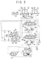
- a hydraulic motor designated by reference numeral 40, is adapted to be driven by an engine M and has a fluid discharge path 40a provided with a turning action dedicated operating valve 41, a plurality of working machine action dedicated operating valves including, for example an arm action dedicated operating valve 42 as well as a boom action dedicated operating valve and a bucket action operating valve (not shown), all of these operating valves being connected parallel to one another.
- a pressure compensation valve 43 Connected at the inlet side of each these valves 41 and 42 and those not shown is a pressure compensation valve 43 which having a check valve portion 44 and a pressure reducing valve portion 45 may be of any of the constructions well known in the art.
- the valve 43 is designed to perform a pressure compensation function under a load pressure P0 for its own associated actuator and a load pressure P1 detected at a load pressure sensing circuit 46. It should be noted that the load pressure sensing circuit 46 has a load pressure introduced therein that becomes the highest when a plurality of hydraulic actuators with which the above mentioned operating valves may be associated are to be operated simultaneously.
- a hydraulic pump 50 which is provided to supply pilot pressure fluid, is designed to be also driven by the above mentioned engine M and has, as shown, connected at its fluid discharge path 51 a hydraulic pilot valve 52 dedicated to an turning operation, an arm operation dedicated hydraulic pilot valve 53.
- the turning operation dedicated hydraulic pilot valve 52 has a first and a second output circuit 54 and 55 connected to the turning action dedicated operating valve 41 at a first and a second pressure receiving portion 41a and 41b thereof, respectively.
- the arm operation dedicated hydraulic pilot valve 53 has a third and a fourth output circuit 56 and 57 connected to the arm action dedicated operating valve 42 at a first and a second pressure receiving portion 42a and 42b, respectively.
- a first sensing circuit 59 is connected via a first shuttle valve 58 to the first and second output circuits 54 and 55 to detect high pressure fluid (pilot pressure fluid) at the latter two.
- the hydraulic circuit 28 mentioned previously is connected via a second shuttle valve 60 to the first sensing circuit 59 and the third output circuit 56 to detect high pressure fluid at the latter two.
- the hydraulic pilot valve 52, 53 is adapted, with a lever 52a, 53a operated in one direction, to furnish pilot pressure fluid to the first, third output circuit 54, 56 and with the same lever operated in the opposite direction, to furnish pilot pressure fluid to the second, fourth output circuit 55, 57.
- releasing the braking apparatus from its braking state by using a pilot pressure fluid furnished from a hydraulic pilot valve, 52 dedicated to a turning action, 53 dedicated to an arm action allows the braking apparatus to be automatically released from its braking state when the hydraulic motor 20 dedicated to the turning action is being rotated and the arm action dedicated cylinder assembly (not shown) is being operated, and allows the braking apparatus to be automatically locked into its braking state when the turning action dedicated hydraulic motor 20 is not being operated and the arm action dedicated cylinder assembly is not being operated.
- any separate switching valve or controller for performing a braking action and a braking release action is made unnecessary.
- the hydraulic pump 40 is designed to be a variable displacement pump with its displacement controllably increased and decreased by changing the angle of inclination of a swash plate 70 with a control piston 71.
- the control piston 71 is slidably displaced under a self-discharge pressure (i. e. a discharge pressure of the hydraulic motor 40) of fluid supplied into a small pressure receiving chamber 72 and a large pressure receiving chamber 73 in the directions in which a pump displacement is increased and decreased.
- the self-discharge pressure fluid is supplied into the large pressure receiving chamber 73 via the control valve 74 which is switching operated under both a load pressure and the self-discharge pressure so that the displacement of the hydraulic pump 40 may be controlled so as to maintain the balance between the self-discharge pressure and the load pressure (P0-P1) substantially constant.
- the above mentioned operating valves 41 and 42 are designed to be each of closed center type in which when it is in its neutral position A its inlet port is closed.
- the operating valve 41, 42 is brought into its neutral position A to make the load pressure zero, thus minimizing the displacement of the hydraulic motor 40 to reduce the self-discharge pressure and in turn to diminish the driving horse power of the engine M.
- the operating valve is switched to assume its first position B or second position C, a consequential rise in the load pressure causes the displacement of the hydraulic motor 40 to be increased and in turn its self-discharge pressure to be elevated.
- the balance between the self-discharge pressure and the load pressure are so maintained constant.
- a housing 80 has formed in it a bore 81 that is in fluid communication with the piston pressure receiving chamber 27, and a fluid bore 82 that is in fluid communication with the bore 81, providing the hydraulic circuit 28 shown in Fig. 3.
- the bore 81 has a spool 83 slidably inserted therein, which as shown in Fig. 5 is formed with a small diameter end portion 84, an intermediate land portion 85, an annular groove 86 and a large diameter base portion 87.
- a slit 88 is formed diametrically and is formed on a bottom thereof with an axial bore 89 that is in fluid communication via a port 90 with the annular groove portion 86 and also in fluid communication with the rear end face of the spool 83.
- the spool 83 is pushed by a spring 91 against the piston 25, and the piston pressure receiving chamber 27 is in fluid communication with a spring chamber 92 (corresponding to the pressure receiving portion 31) via the axial bore 89.
- the fluid bore 82 is held in fluid communication with the piston pressure receiving chamber 27 via an annular space 93 formed between the small diameter end portion 84 and the bore 81, the port 90 and the axial bore 89. Then, the fluid bore 82 and the piston pressure receiving chamber 24 have an enlarged area of opening or fluid communication between them.
- Displacement of the piston 25 in the braking release direction causes the intermediate land 85 to reduce an area of opening between the fluid bore 82 and the annular space 93 and thereby the area of opening or fluid communication between the fluid bore 82 and the piston pressure receiving chamber 27 to be reduced.
- Fig. 6 shows a second embodiment of the present invention having the turning action dedicated operating valve 41 and the arm action dedicated operating valve 42 each constituted to be of open center type in which when the valve is held in its neutral position its inlet port is in fluid communication with a reservoir.
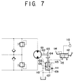
- a turning action dedicated hydraulic motor 101 has a rotary portion 102 that has a friction plate (rotation side friction plate) 103 secured to it.
- Another friction plate (fixed side friction plate) 104 and a braking cylinder assembly 105 are secured to a fixed portion of the hydraulic motor 101 such as a housing of it.
- a piston 106 in the braking cylinder assembly 105 is adapted to be movable in a braking direction to urge the fixed side friction plate 104 into a pressure contact with the rotation side friction plate 103.
- the piston 106 is also displaceable under fluid pressure in a piston pressure receiving chamber 108 in a braking release direction such as to separate the fixed side friction plate 104 away from the rotation side friction plate 103.
- the drain circuit 109 Connected to the piston pressure receiving chamber 108 is a drain circuit 109 which is in turn connected to an internal drain path 110 of the hydraulic motor 101.
- the drain circuit 109 has a restriction 111 provided therein.
- the piston pressure receiving chamber 108 is adapted to be connected by a switching valve 112 alternately with a fluid pressure source 113 and a reservoir 114.
- the spring 107 urges the fixed side friction plate 104 into a firm pressure contact with the rotation side friction plate 103, permitting a braking torque that is commensurate with the spring force to ensue.
- Fig. 8 shows a fourth embodiment of the present invention in which a hydraulic pump 120 adapted to be driven by an engine M has in a discharge path 120a thereof a turning action dedicated operating valve 121 and a working machine action dedicated operating valve 122 connected in parallel so that pressure fluid may be supplied into the turning action dedicated hydraulic motor 101 as well as into a working machine action dedicated actuator such as a working machine action dedicated cylinder assembly not shown.
- Each of these operating valves has at its inlet side a pressure compensation valve 123 which may be of any type well known in the art, having a check valve portion 124 and a pressure reducing valve portion 125 to effect a pressure compensation according to a load pressure P0 of its associated hydraulic actuator and a load pressure P1 from a load pressure sensing circuit 126.
- the load pressure sensing circuit 126 has introduced in it a load pressure that becomes highest when a plurality of the actuators are simultaneously operated.
- the hydraulic pump 120 is designed to be a variable displacement pump with its displacement controllably increased and decreased by changing the angle of inclination of a swash plate 120 with a control piston 128.
- the control piston 128 is slidably displaced under a self-discharge pressure (i. e. a discharge pressure of the hydraulic motor 120) of fluid supplied into a small pressure receiving chamber 129 and a large pressure receiving chamber 130 in the directions in which pump displacements are increased and decreased.
- the self-discharge pressure fluid is supplied into the large pressure receiving chamber 130 by the control valve 131 which is switching operated under both a load pressure and the self-discharge pressure so that the displacement of the hydraulic pump 120 may be controlled so as to maintain the balance between the self-discharge pressure and the load pressure substantially constant.
- providing a hydraulic pump 120 with its displacement controllable in this fashion and providing pressure compensation valves 123 allows discharge pressure fluid of a single hydraulic pump 120 to be supplied into a plurality of hydraulic actuators with a plurality of the operating valves operated simultaneously and at a ratio of fluid flows divided in proportion to the areas of opening of these operating valves.
- a hydraulic pump 140 which is provided to supply pilot pressure fluid, is designed to be driven by the engine M and has, as shown, connected at its fluid discharge path 140a a hydraulic pilot valve 141 dedicated to an turning operation, a working operation dedicated hydraulic pilot valve 142.
- the turning operation dedicated hydraulic pilot valve 141 has a first and a second output circuit 143 and 144 connected to the turning operation dedicated operating valve 121 at a first and a second pressure receiving portion 121a and 121b thereof, respectively.
- the working operation dedicated hydraulic pilot valve 142 has a third and a fourth output circuit 145 and 146 connected to the working operation dedicated operating valve 122 at a first and a second pressure receiving portion 122a and 122b, respectively.
- the first output circuit 143 and the second output circuit 144 are connected to the inlet side of a first shuttle valve 147.
- the outlet side of the shuttle valve 147 and the third output circuit 145 are connected to the inlet side of a second shuttle valve 148 whose outlet side is connected via a hydraulic circuit 149 to the piston pressure receiving chamber 108 of the braking cylinder assembly 105.
- the turning operation dedicated hydraulic pilot valve 141 is operated to furnish pilot pressure fluid to the first output circuit 143 or the second output circuit 144, thereby switching the turning action operating valve 121 to its first position B or second position C to rotate the hydraulic motor 101 normally or reversely.
- the pilot pressure fluid furnished from the turning operation dedicated hydraulic pilot valve 141 flows through the hydraulic circuit 149 and is supplied into the piston pressure receiving chamber 108 in the braking cylinder assembly 105 to release the braking apparatus from its braking state. Then, air that remains in the hydraulic circuit 149 is expelled in a manner as mentioned previously.
- Fig. 9 shows a fifth embodiment of the present invention in which a piston pressure receiving chamber 108 of a braking cylinder assembly 105 is connected to a load pressure sensing circuit 126.
- This embodiment thus allows the braking apparatus to be brought into a braking release state with a load pressure in the turning action dedicated hydraulic motor 101 or with a load pressure in a working action dedicated cylinder assembly.
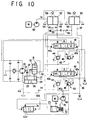
- Fig. 10 shows a fifth embodiment of the present invention, which is designed to add an air extracting arrangement as included in the aforementioned third embodiment to the first embodiment previously described.
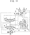
- Fig. 11 shows a seventh embodiment of the present invention, that is designed to add an air extracting arrangement as included in the aforementioned third embodiment to the second embodiment previously described.
- a sleeve 150 has an outer peripheral surface 150a formed with an annular recess 151 that communicates via bore 152 with an inner peripheral surface 150b of the sleeve 150.
- a piston 153 which is slidably fitted in the sleeve 150, is of a stepped shape having a large diameter portion 154 and a small diameter portion 155 and is axially formed with a bore 156.
- a portion of the bore 156 that is closer to its bottom is formed to communicate via a small bore 157 with the small diameter portion 155, and a plurality of balls 158 which are smaller in diameter than the inner diameter of the bore 156 are slidably fitted in the bore 156 of the piston 153.
- a space between the large diameter portion 154 of the piston 153 and the inner peripheral surface 150b of the sleeve 150 is sealed with a sealing material 159, and the small bore 157 is formed to communicate with a small bore 160 of the sleeve 150 so that pressure fluid introduced through the bore 152 may flow through the small bore 157 and an interstice which are formed by the wall of the small bore 157 and the balls 158 and flows out of the small bore 160.
- the interstice between the wall of the bore 156 and the balls 158 which is essentially defined by a difference in diameter between the bore 156 and the balls 158, thus provides a restriction that is compact and highly effective to restrict a flow of pressure fluid when passing through the interstice.
- the interstice that is formed between the wall of the bore 156 and the balls 158 being annular, it can be seen that a block of one portion of the interstice with a foreign matter permits pressure fluid to flow through another portion of the interstice.
Landscapes
- Engineering & Computer Science (AREA)
- Mining & Mineral Resources (AREA)
- Civil Engineering (AREA)
- General Engineering & Computer Science (AREA)
- Structural Engineering (AREA)
- Hydraulic Motors (AREA)
- Fluid-Pressure Circuits (AREA)
Applications Claiming Priority (5)
| Application Number | Priority Date | Filing Date | Title |
|---|---|---|---|
| JP07195696A JP3745442B2 (ja) | 1996-03-27 | 1996-03-27 | 油圧モータのブレーキ装置 |
| JP71956/96 | 1996-03-27 | ||
| JP7200096A JPH09264346A (ja) | 1996-03-27 | 1996-03-27 | 油圧モータのブレーキ装置 |
| JP72000/96 | 1996-03-27 | ||
| PCT/JP1997/001057 WO1997036062A1 (fr) | 1996-03-27 | 1997-03-27 | Dispositif de freinage pour moteur hydraulique a huile |
Publications (1)
| Publication Number | Publication Date |
|---|---|
| EP0897036A1 true EP0897036A1 (de) | 1999-02-17 |
Family
ID=26413078
Family Applications (1)
| Application Number | Title | Priority Date | Filing Date |
|---|---|---|---|
| EP97908530A Withdrawn EP0897036A1 (de) | 1996-03-27 | 1997-03-27 | Bremsvorrichtung für einen öl-hydraulischen motor |
Country Status (3)
| Country | Link |
|---|---|
| US (1) | US6050091A (de) |
| EP (1) | EP0897036A1 (de) |
| WO (1) | WO1997036062A1 (de) |
Cited By (1)
| Publication number | Priority date | Publication date | Assignee | Title |
|---|---|---|---|---|
| DE102005056981A1 (de) * | 2005-11-30 | 2007-06-06 | Sauer-Danfoss Aps | Arbeitsmaschine, insbesondere Minibagger |
Families Citing this family (12)
| Publication number | Priority date | Publication date | Assignee | Title |
|---|---|---|---|---|
| FR2849142B1 (fr) * | 2002-12-20 | 2007-01-26 | Poclain Hydraulics Ind | Systeme de freinage pour un vehicule entraine par au moins un moteur hydraulique alimente en circuit ferme |
| US20070210643A1 (en) * | 2004-05-21 | 2007-09-13 | White Hydraulics, Inc. | Hydraulic Motor and Brake Control System and Method of Controlling the Same |
| US7249806B1 (en) * | 2004-05-21 | 2007-07-31 | White Drive Products, Inc. | Hydraulic motor and brake control system and method of controlling the same |
| US7222370B2 (en) * | 2004-12-22 | 2007-05-29 | Rawlings Sporting Goods Company, Inc. | Protective eyewear with metal lenses |
| US7914084B2 (en) * | 2006-02-02 | 2011-03-29 | White Drive Products, Inc. | Control component for hydraulic circuit including spring applied-hydraulically released brake |
| US7722131B2 (en) * | 2006-02-02 | 2010-05-25 | White Drive Products, Inc. | Control component for a spring applied-pressure released hydraulic brake and hydraulic motor |
| WO2007089305A1 (en) * | 2006-02-02 | 2007-08-09 | White Drive Products, Inc. | Control component for hydraulic circuit including spring applied-hydraulically released brake |
| US7909414B2 (en) * | 2006-03-10 | 2011-03-22 | White Drive Products, Inc. | Hydraulic circuit for spring applied-hydraulically released brake and hydraulic motor |
| US8510000B2 (en) * | 2008-03-26 | 2013-08-13 | Kayaba Industry Co., Ltd. | Hybrid construction machine |
| US8534431B2 (en) | 2010-07-21 | 2013-09-17 | Warn Industries, Inc. | Face tooth hydraulic piston brake |
| JP7347925B2 (ja) * | 2018-11-19 | 2023-09-20 | 株式会社小松製作所 | 作業車両、動力機械の制御装置および制御方法 |
| CN113107922B (zh) * | 2021-03-16 | 2022-11-04 | 北京天玛智控科技股份有限公司 | 液压马达和调压装置 |
Family Cites Families (22)
| Publication number | Priority date | Publication date | Assignee | Title |
|---|---|---|---|---|
| JPS609092Y2 (ja) * | 1978-11-28 | 1985-04-01 | 株式会社小松製作所 | 油圧駆動車両のインチングブレ−キ制御回路 |
| JPS5810601B2 (ja) * | 1978-12-20 | 1983-02-26 | 日立建機株式会社 | 油圧走行装置の油圧回路 |
| JPS55139505A (en) * | 1979-04-19 | 1980-10-31 | Hitachi Constr Mach Co Ltd | Hydraulic circuit for rotary machine |
| JPS57110857A (en) * | 1980-12-27 | 1982-07-09 | Hitachi Constr Mach Co Ltd | Controller of oil hydraulic device |
| JPS57110858A (en) * | 1980-12-27 | 1982-07-09 | Hitachi Constr Mach Co Ltd | Controller of oil hydraulic system |
| JPS57110860A (en) * | 1980-12-27 | 1982-07-09 | Hitachi Constr Mach Co Ltd | Controller of oil hydraulic system |
| JPS57110855A (en) * | 1980-12-27 | 1982-07-09 | Hitachi Constr Mach Co Ltd | Controller of oil hydraulic device |
| JPS5893624A (ja) * | 1981-11-30 | 1983-06-03 | Komatsu Ltd | 油圧駆動車の制御装置 |
| JPS591864A (ja) * | 1982-06-29 | 1984-01-07 | Kayaba Ind Co Ltd | 油圧モ−タのブレ−キ制御回路 |
| US4543786A (en) * | 1983-07-14 | 1985-10-01 | Caterpillar Tractor Co. | Control system for hydrostatic transmission |
| JPS60129503U (ja) * | 1984-02-10 | 1985-08-30 | 株式会社小松製作所 | 旋回油圧回路 |
| JPS6197060A (ja) * | 1984-10-19 | 1986-05-15 | Hitachi Ltd | 発泡断熱材原料混合吐出装置 |
| JPS6197060U (de) * | 1984-12-03 | 1986-06-21 | ||
| JPS62106104A (ja) * | 1985-07-17 | 1987-05-16 | Hitachi Constr Mach Co Ltd | 油圧モ−タのブレ−キ回路 |
| JPS62100306A (ja) * | 1985-10-25 | 1987-05-09 | Kobe Steel Ltd | ベルトコンベアの蛇行制御装置 |
| JPS62100306U (de) * | 1985-12-16 | 1987-06-26 | ||
| US4694647A (en) * | 1986-03-28 | 1987-09-22 | Kabushiki Kaisha Komatsu Seisakusho | Hydraulic circuit system for use in hydraulically operated vehicles |
| GB2204652B (en) * | 1987-05-09 | 1991-05-15 | Kubota Ltd | Fluid pressure control circuit for working vehicle having transmission operable by fluid pressure |
| JPH06321089A (ja) * | 1993-05-10 | 1994-11-22 | Kubota Corp | 作業車の油圧アクチュエータ操作構造 |
| JP3404700B2 (ja) * | 1994-06-17 | 2003-05-12 | カヤバ工業株式会社 | 車両用油圧走行モータの駐車ブレーキ解除装置 |
| JP3449797B2 (ja) * | 1994-08-22 | 2003-09-22 | 帝人製機株式会社 | 流体装置 |
| US5709083A (en) * | 1996-08-15 | 1998-01-20 | Caterpillar Inc. | Hydraulic swing motor deceleration control |
-
1997
- 1997-03-27 US US09/125,219 patent/US6050091A/en not_active Expired - Lifetime
- 1997-03-27 WO PCT/JP1997/001057 patent/WO1997036062A1/ja not_active Application Discontinuation
- 1997-03-27 EP EP97908530A patent/EP0897036A1/de not_active Withdrawn
Non-Patent Citations (1)
| Title |
|---|
| See references of WO9736062A1 * |
Cited By (2)
| Publication number | Priority date | Publication date | Assignee | Title |
|---|---|---|---|---|
| DE102005056981A1 (de) * | 2005-11-30 | 2007-06-06 | Sauer-Danfoss Aps | Arbeitsmaschine, insbesondere Minibagger |
| DE102005056981B4 (de) * | 2005-11-30 | 2007-09-27 | Sauer-Danfoss Aps | Arbeitsmaschine, insbesondere Minibagger |
Also Published As
| Publication number | Publication date |
|---|---|
| WO1997036062A1 (fr) | 1997-10-02 |
| US6050091A (en) | 2000-04-18 |
Similar Documents
| Publication | Publication Date | Title |
|---|---|---|
| US6050091A (en) | Brake device for oil hydraulic motor | |
| KR101196595B1 (ko) | 수압식 구동 시스템 및 이를 위한 개선된 제어 밸브어셈블리 | |
| US6715403B2 (en) | Independent and regenerative mode fluid control system | |
| KR100742253B1 (ko) | 유압펌프의 용량제어장치 및 유압모터의 브레이크 제어장치 | |
| JP2004003652A (ja) | 油圧再生システム | |
| JP2017179923A (ja) | 作業機の油圧システム | |
| KR100326890B1 (ko) | 유압모터의브레이크장치 | |
| JP2009121649A (ja) | 油圧回路並びに作業機械 | |
| JPH11311207A (ja) | 作業車両の作業油圧用の弁ユニット | |
| WO2016169939A1 (en) | Hydraulic circuit and working machine | |
| JP2009250204A (ja) | アキシャルピストン装置及び油圧回路並びに作業機械 | |
| JP6847821B2 (ja) | 作業機の油圧システム | |
| JP6682496B2 (ja) | 作業機の油圧システム | |
| US6606858B2 (en) | Neutral override for servo controlled hydrostatic units | |
| JPH0893708A (ja) | 油圧回路 | |
| JP2538677B2 (ja) | 作業車のブレ―キ構造 | |
| JP6766030B2 (ja) | 作業機の油圧システム | |
| JPH108506A (ja) | パワー機械 | |
| JP2009121435A (ja) | アキシャルピストン装置及び油圧回路並びに作業機械 | |
| CN215170574U (zh) | 活塞式液压装置 | |
| JPH0872570A (ja) | 走行用油圧モータ制御装置 | |
| CN214662227U (zh) | 用于再生功能的比例阀 | |
| JPS63235702A (ja) | 油圧モ−タの制御装置 | |
| JP3745442B2 (ja) | 油圧モータのブレーキ装置 | |
| JPH0571796B2 (de) |
Legal Events
| Date | Code | Title | Description |
|---|---|---|---|
| PUAI | Public reference made under article 153(3) epc to a published international application that has entered the european phase |
Free format text: ORIGINAL CODE: 0009012 |
|
| 17P | Request for examination filed |
Effective date: 19980818 |
|
| AK | Designated contracting states |
Kind code of ref document: A1 Designated state(s): DE |
|
| STAA | Information on the status of an ep patent application or granted ep patent |
Free format text: STATUS: THE APPLICATION HAS BEEN WITHDRAWN |
|
| 18W | Application withdrawn |
Withdrawal date: 19991004 |