TECHNICAL FIELD
-
The present invention relates to a braking apparatus
for a hydraulic motor, e.g., a hydraulic motor that is
adapted for use in turning an upper vehicle body in a power
shovel.
BACKGROUND ART
-
In the art there has hitherto been known a hydraulic
motor in which a cylinder block is mounted in a housing so
as to be axially rotatable. The cylinder block contains a
cylinder bore in which a piston is slidably inserted
providing a cylinder chamber such that with a leading end
portion of the piston slidably driven along a swash plate an
axial sliding movement of the piston may be effected. Fluid
communication of the cylinder chamber alternate with a
hydraulic supply and a reservoir allows the cylinder block
to be axially rotated.
-
A known braking apparatus for a hydraulic motor of
the type described is illustrated in Fig. 1. As illustrated,
a cylinder block 1 and a housing 2 have rotatable side
friction plates 3 and fixed side friction plates 4 attached
respectively thereto and arranged together so that a former
plate and a latter plate may be placed alternately. A piston
5, which is juxtaposed with a friction plate arrangement of
these plates 3 and 4, is pushed by a spring 6 to bring the
fixed side and rotation side friction plates 4 and 3 into a
mutual pressure contact, thereby applying a braking to a
movement of the cylinder block 1. Supplying a fluid under an
elevated pressure into a pressure receiving chamber 7 for
the piston 5 causes the piston 5 to be displaced against a
resilient pressure by the spring 6 to separate the fixed
side friction plates 4 and the rotation side friction plates
3 away from one another, thereby releasing the braking force
applied to the cylinder block 1.
-
A further detail of the braking apparatus shown and
described is schematically illustrated in Fig. 2 for a
hydraulic motor 10. Disposed as juxtaposed with a rotating
part 11 of the hydraulic motor 10 is a braking cylinder
assembly 12 having a piston 13. The piston 13 is adapted to
be displaced in a braking direction (here in the direction
in which it is extended) as energized by a spring 14 and to
be displaced in the opposite direction (here in the
direction in which it is retracted) to release the braking
when a piston pressure receiving cylinder chamber 15 is
supplied with a pressure fluid.
-
A pressure fluid for supplying into the piston
pressure receiving chamber 15 in the braking cylinder
assembly 12 (a braking release pressure fluid) may well be
an output pressure fluid delivered from a hydraulic pilot
valve which is designed for a hydraulic motor, i. e. a valve
to provide a pilot pressure fluid for switching an operating
valve used to hydraulically drive the motor.
-
Typically, a hydraulic power shovel comprises a
plurality of hydraulic actuators including a boom cylinder,
an arm cylinder and a bucket cylinder, a plurality of
operating hydraulic valves used to supply pressure fluid to
these actuators, including a boom operating hydraulic valve,
an arm operating hydraulic valve and a bucket operating
hydraulic valve and a plurality of pilot valves for
supplying pilot switching pressure fluid to these operating
valves, including a boom associated pilot valve, an arm
associated pilot valve and a bucket associated pilot valve.
Each of these pilot valves and a hydraulic motor associated
pilot valve mentioned in the preceding paragraph are coupled
to and located at the discharge outlet of a single hydraulic
pump.
-
The piston pressure receiving chamber 15 in the
braking cylinder assembly 12 has a large pressure receiving
area and also provides a long piston stroke in the braking
release direction. Hence, displacing the piston 13 to the
extent of its stroke end in order to release braking with
the braking apparatus requires a plenty of pressure fluid to
be supplied into the piston pressure receiving chamber 15 in
the braking cylinder assembly 12.
-
In a compound operation in which the hydraulic motor
and the arm are simultaneously operated to perform a turning
operation and an arm control operation at the same time,
supply of a plenty of pressure fluid from the hydraulic
motor associated pilot valve into the piston pressure
receiving chamber 15 in the braking cylinder assembly 12
extremely reduces the pressure of pilot pressure fluid,
however. A delay may then be caused in the switching of the
arm operating hydraulic valve by a failure of the piston 13
of the braking cylinder assembly 12 to be moved to the
extent of its stroke end, deteriorating the operating
performance of any of the other component associated
hydraulic actuators in such a compound operation.
-
In the braking apparatus described, a means such as
a switching valve may also be used to supply pressure fluid
into the piston pressure receiving chamber 15 in the braking
cylinder 12, or to allow pressure fluid to flow out of the
piston pressure receiving chamber into a reservoir. It has
then be experienced, however, that air tends to be entrapped
in a circuit connecting the switching valve to the piston
pressure receiving chamber of the braking cylinder assembly,
a fluid passage in the switching valve and a circuit
connecting the switching valve to the reservoir, assembled
or while being assembled, and such air entrapment could
seldom be expelled or extracted. The entrapment of air that
remains lengthens the time which is elapsed actually for a
breaking, i.e. the time from an instant at which the
braking apparatus is acted on to commence releasing a
breaking up to an instant when the fluid pressure in the
piston pressure receiving chamber has been built up to a
pre-established level to complete the braking release
action.
-
It is accordingly an object of the present invention
to provide a braking apparatus for a hydraulic motor, that
can resolve the problem mentioned above.
SUMMARY OF THE INVENTION
-
In order to achieve the above mentioned object,
there is provided in accordance with the present invention
in a first form of embodiment thereof a braking apparatus
for a hydraulic motor, which comprises:
- a rotary side friction plate coupled to a rotary
component of the hydraulic motor;
- a fixed side friction plate coupled to a fixed
component of the hydraulic motor;
- a braking cylinder assembly having a piston, a
piston pressure receiving chamber and a spring, wherein the
said piston is adapted to be energized by the said spring to
move in a braking direction for bringing the said fixed side
friction plate and the said rotary side friction plate into
a pressure contact, and the said piston pressure receiving
chamber is adapted to be supplied with pressure fluid to
displace the said piston in a braking release direction for
separate the said fixed side friction plate and the said
rotary side friction plate from each other;
- an operating valve for supplying pressure fluid into
the said hydraulic motor;
- a hydraulic pilot valve for providing pilot pressure
fluid for use to switch the said operating valve;
- a hydraulic circuit for delivering pilot pressure
fluid from the said hydraulic pilot valve into the said
piston pressure receiving chamber; and
- a fluid flow control means in the said hydraulic
circuit and having an area of opening progressively reduced
as a function of a distance of travel of the said piston
moving and displaced from a braking position towards a
braking release position.
-
-
According to the construction mentioned above, it
can be seen and should be understood that pilot pressure
fluid from a hydraulic pilot valve for use to switch an
operating valve, e.g., a valve for providing a turning
action, may effectively be used to displace the piston in
the braking cylinder assembly in a breaking release
direction, thereby releasing a braking action applied by the
braking apparatus.
-
Accordingly, since just an operation such as to
rotate a hydraulic motor for proving the turning action
allows a braking apparatus to be automatically released, not
only will the entire hydraulic system be freed from
malfunctioning, but it makes it unnecessary to operate a
braking apparatus separately, thus simplifying operations
thereof.
-
In the braking apparatus according to the present
invention, it should also be noted that the flow of pressure
fluid supplied into the piston pressure receiving chamber in
the braking cylinder assembly is great in an initial period
of the operation in which the piston is displaced from the
breaking position towards a breaking release position, is
reduced progressively thereafter as a function of the
distance of travel of the piston and is small when the
piston is displaced until it reaches its stroke end, thus
providing an accelerated breaking release operation by the
time at which the fixed side friction plate is separated
from the rotation side friction plate. Any significant
pressure drop of the pilot fluid from the hydraulic pilot
valve is also avoided.
-
It follows, therefore, that in a compound operation
in which a hydraulic motor and other hydraulic actuators are
simultaneously driven with a plurality of operating valves
switched by pilot pressure fluid from a plurality of pilot
valves, there should be no substantial pressure drop in
pressure fluid delivered from any of these pilot valves,
permitting their respective associated operating valves to
be switched smoothly, giving rise to no deterioration in
operating performance of the other hydraulic actuators.
-
In the construction described above, the said flow
control means may include:
- a fluid control bore disposed in a housing of the
said hydraulic motor and being in fluid communication with
the said piston pressure receiving chamber;
- a fluid inlet bore being in communication with the
said fluid control bore through an area of fluid
communication and adapted to accept the pilot pressure fluid
from the said hydraulic pilot valve;
- a spool slidably fitted in the said fluid control
bore;
- a spring chamber defined at one end side of the said
spool;
- a spring accommodated in the said spring chamber for
urging the said spool in contact with the said piston; and
- an axial bore formed in the said spool for normally
maintaining the said piston pressure receiving chamber and
the said fluid inlet bore in communication with the said
spring chamber,
wherein the said spool is shaped so as to allow the
area of fluid communication between the said fluid inlet
bore and the said piston pressure receiving chamber to be
progressively reduced as a function of a distance of travel
of the said spool displaced towards the said piston. -
-
According to the construction mentioned above, it
can be seen and should be understood that providing the flow
control means in a housing of the hydraulic motor makes the
flow control means not to dispose separately in a portion of
a pipe arrangement for coupling an output circuit of any of
the hydraulic pilot valves and the piston pressure receiving
chamber in the braking cylinder assembly and thus simplifies
the pipe arrangement.
-
The present invention also provides in a second
form of embodiment thereof, a braking apparatus for a
hydraulic motor, which comprises:
- a rotary side friction plate coupled to a rotary
component of the hydraulic motor;
- a fixed side friction plate coupled to a fixed
component of the hydraulic motor;
- a braking cylinder assembly having a piston, a
piston pressure receiving chamber and a spring, wherein the
said piston is adapted to be energized by the said spring to
move in a braking direction for bringing the said fixed side
friction plate and the said rotary side friction plate into
a pressure contact, and the said piston pressure receiving
chamber is adapted to be supplied with pressure fluid to
displace the said piston in a braking release direction for
separating the said fixed side friction plate and the said
rotary side friction plate from each other;
- a pressure fluid supply means for supplying and
terminating a supply of, pressure fluid into the said piston
pressure receiving chamber;
- a hydraulic circuit for delivering pressure fluid
from the said pressure fluid supply means to the said piston
pressure receiving chamber; and
- a drain circuit for establishing a fluid
communication of the said piston chamber with an internal
drain path of said hydraulic motor.
-
-
According to the construction mentioned above, it
can be seen and should be understood that the pressure fluid
supply means supplying pressure fluid into the piston
pressure receiving chamber allows air introduced into the
hydraulic circuit that couples together the pressure fluid
supply means and the piston pressure receiving chamber to be
led out through the said drain circuit into an internal
drain path of the hydraulic motor, and hence provide a
complete removal of air that may have been entrained into
the braking apparatus, e. g., while it is assembled.
-
This permits the pressure in the piston pressure
receiving chamber of the braking apparatus to be elevated to
a predetermined level in a short period of time to displace
the piston quickly in the breaking release direction until
it reaches its stroke end, and hence provides a reduction in
the time period expended from the time instant of starting a
braking release operation up to the time instant at which
the braking release has been accomplished.
-
Also, since the pressure fluid in the piston
pressure receiving chamber is allowed to flow from the drain
circuit into the internal drain path of the hydraulic motor
when the piston in the braking chamber is displaced in the
braking release direction, there could be no material
pressure then left in the piston pressure receiving chamber
or in a hydraulic circuit mentioned as above, eventually
permitting the fixed side friction plate to establish a
pressure contact with the rotation side friction plate under
the spring force of a spring.
-
This effectively provides producing a braking torque
that is commensurate with the spring force of the spring.
-
In the construction described above, it should be
noted that the said pressure fluid supply means may be
constituted by a separate source of pressure.
-
Also, in the construction described above, the said
pressure fluid supply means may be constituted by a
hydraulic pilot valve for providing pilot pressure fluid for
use to switch an operating valve that is dedicated for
supplying pressure fluid into the hydraulic motor.
-
According to the construction mentioned above, it
can be seen and should be understood that rotation of the
hydraulic motor with the operating valve therefor switched
with pilot pressure fluid furnished from the corresponding
pilot valve causes displacement of the piston in the braking
release direction and establishes a braking release state
for the braking apparatus.
-
Thus, releasing the braking apparatus from a braking
state following the hydraulic motor, e. g., driven to rotate
makes its braking operation simplified.
-
The braking apparatus can also be released from its
braking state when the hydraulic motor ceases driving with
its associated operating valve switched into its neutral
position by bringing the pilot valve dedicated thereto into
its neutral position to cause the pressure fluid in the
piston pressure receiving chamber of the braking cylinder
assembly to flow out into an internal drain path of the
hydraulic motor.
-
In the construction mentioned above, the said
pressure fluid supply means may be constituted by a
hydraulic pilot valve for providing pilot pressure fluid for
use to switch an operating valve that is dedicated for
supplying pressure fluid into the hydraulic motor.
-
According to the construction described above, it
can be seen and should be understood that the development of
a load pressure in the hydraulic motor that is driven into a
rotation or the development of a load pressure in any of the
actuators that is operated to be driven in a working
machine displaces the piston of the braking cylinder
assembly in the braking release direction under such a load
pressure and thus establishes a braking release state for
the braking apparatus.
-
This allows an operation to rotate the hydraulic
motor or an operation to cause any of the actuators in a
working machine to be driven brings the braking apparatus
into a braking release state and thus makes its operation
simplified.
-
The present invention further provides in a third
form of embodiment thereof a braking apparatus for a
hydraulic motor which includes a drain circuit for
establishing a fluid communication of the said piston
chamber with an internal drain path of the hydraulic motor.
BRIEF DESCRIPTION OF THE DRAWINGS
-
The present invention will better be understood from
the following detailed description and the drawings attached
hereto showing certain illustrative embodiments of the
present invention. In this connection, it should be noted
that such embodiments as illustrated in the accompanying
drawings are intended in no way to limit the present
invention but to facilitate an explanation and understanding
thereof.
-
In the accompanying drawings:
- Fig. 1 is a cross sectional view that shows a
conventional braking apparatus for a hydraulic motor;
- Fig. 2 is a schematic diagram of the conventional
for a hydraulic motor;
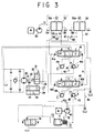
- Fig. 3 is a schematic diagram that shows a first
embodiment of a braking apparatus for a hydraulic motor
provided in accordance with the present invention;
- Fig. 4 is a cross sectional view that shows a
specific structure of a flow control means that is included
in the said first embodiment of the present invention;
- Fig. 5 is a perspective view that shows a spool that
is included in the said flow control means;
- Fig. 6 is a schematic diagram that shows a second
embodiment of a braking apparatus according to the present
invention;
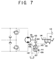
- Fig. 7 is a schematic diagram that shows a third
embodiment of a braking apparatus according to the present
invention;
- Fig. 8 is a schematic diagram that shows a fourth
embodiment of a braking apparatus according to the present
invention;
- Fig. 9 is schematic diagram that shows a fifth
embodiment of a braking apparatus according to the present
invention;
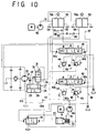
- Fig. 10 is a schematic diagram that shows a sixth
embodiment of a braking apparatus according to the present
invention;
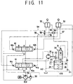
- Fig. 11 is a schematic diagram that shows a seventh
embodiment of a braking apparatus according to the present
invention; and
- Fig. 12 is a cross sectional view that shows a
specific structure of a restriction that may be included in
the said third through seventh embodiments of the invention.
-
BEST MODES FOR CARRYING OUT THE INVENTION
-
Hereinafter, suitable embodiments of the present
invention with regard to a braking apparatus for a hydraulic
motor are set forth with reference to the accompanying
drawings hereof.
-
As shown in Fig. 3, a hydraulic motor 20 that is
adapted for use in turning an object includes a rotary
portion 21 that has a rotation side friction plate 22
attached thereto. A fixed side friction plate 23 that is
attached to a fixed side of the hydraulic motor is adapted
for displacement by a braking cylinder assembly 24. The
braking cylinder assembly 24 has a piston 25 that is adapted
to be mechanically energized by a spring 26 in a direction
in which it is extended to apply a braking action (in a
braking direction) and to be displaceable in a piston
pressure receiving chamber 27 in a direction in which it is
retracted (in a braking release direction).
-
Connected to the piston pressure receiving chamber
27 is a hydraulic circuit 28 that is provided with a fluid
flow control means 30. The fluid flow control means 30 is
adapted to be pushed by pressure fluid in the pressure
receiving chamber 31 in a direction in which its area of
opening is reduced and to be pushed in a direction in which
the area of opening is increased by displacement of the
piston 25 from its breaking release position towards its
braking position. The flow control means 30 has a pressure
receiving portion 31 connected to an upstream side of the
hydraulic circuit 28.
-
A hydraulic motor, designated by reference numeral
40, is adapted to be driven by an engine M and has a fluid
discharge path 40a provided with a turning action dedicated
operating valve 41, a plurality of working machine action
dedicated operating valves including, for example an arm
action dedicated operating valve 42 as well as a boom action
dedicated operating valve and a bucket action operating
valve (not shown), all of these operating valves being
connected parallel to one another. Connected at the inlet
side of each these valves 41 and 42 and those not shown is
a pressure compensation valve 43 which having a check valve
portion 44 and a pressure reducing valve portion 45 may be
of any of the constructions well known in the art. The valve
43 is designed to perform a pressure compensation function
under a load pressure P0 for its own associated actuator and
a load pressure P1 detected at a load pressure sensing
circuit 46. It should be noted that the load pressure
sensing circuit 46 has a load pressure introduced therein
that becomes the highest when a plurality of hydraulic
actuators with which the above mentioned operating valves
may be associated are to be operated simultaneously.
-
A hydraulic pump 50, which is provided to supply
pilot pressure fluid, is designed to be also driven by the
above mentioned engine M and has, as shown, connected at its
fluid discharge path 51 a hydraulic pilot valve 52 dedicated
to an turning operation, an arm operation dedicated
hydraulic pilot valve 53. The turning operation dedicated
hydraulic pilot valve 52 has a first and a second output
circuit 54 and 55 connected to the turning action dedicated
operating valve 41 at a first and a second pressure
receiving portion 41a and 41b thereof, respectively. The arm
operation dedicated hydraulic pilot valve 53 has a third and
a fourth output circuit 56 and 57 connected to the arm
action dedicated operating valve 42 at a first and a second
pressure receiving portion 42a and 42b, respectively.
-
A first sensing circuit 59 is connected via a first
shuttle valve 58 to the first and second output circuits 54
and 55 to detect high pressure fluid (pilot pressure fluid)
at the latter two. The hydraulic circuit 28 mentioned
previously is connected via a second shuttle valve 60 to the
first sensing circuit 59 and the third output circuit 56 to
detect high pressure fluid at the latter two.
-
The hydraulic pilot valve 52, 53 is adapted, with a
lever 52a, 53a operated in one direction, to furnish pilot
pressure fluid to the first, third output circuit 54, 56 and
with the same lever operated in the opposite direction, to
furnish pilot pressure fluid to the second, fourth output
circuit 55, 57.
-
Operating the lever 52a for the turning operation
dedicated hydraulic pilot valve 52 in the one or the other
direction to furnish pilot pressure fluid to the first or
second output circuit 54 or 55 switches the turning action
dedicated operating valve 41 from its neutral position A to
its first position B or its second position C while
operating the lever 53a for the arm operation dedicated
hydraulic pilot valve 53 in the one direction to furnish
pilot pressure fluid to the third output circuit 56 switches
the arm action dedicated operating valve 42 to its second
position B. Switching the turning action dedicated operating
valve 41 from to its first position B or its second position
C while switching the arm action dedicated operating valve
42 to its second position B furnishes pilot pressure fluid
to the hydraulic circuit 28, thereby supplying pressure
fluid into the piston pressure receiving chamber 27 to
release the braking apparatus from its braking state.
-
An explanation will now be given in detail of an
operation of the braking apparatus described.
-
In the state shown in Fig. 3, the piston 25 in the
braking cylinder assembly 24 is pushed by the spring 26 in
the braking direction to urge the fixed side friction plate
23 into pressure contact with the rotation side friction
plate 22 to hold the braking apparatus in braking state. The
flow control means 30 has then its area of opening enlarged.
-
When pressure fluid flows into the hydraulic circuit
28, a plenty of the pressure fluid supplied past the flow
control valve 30 into the piston pressure receiving chamber
27 causes rapid displacement of the piston 25 against the
spring 26 in the braking release direction to separate the
fixed side friction plate 23 away from the rotation side
friction plate 22 to release the braking apparatus from its
braking state.
-
At the same time, the flow control valve 30 with
pressure fluid from the hydraulic circuit 28 acting on its
pressure receiving portion 31 is pushed towards a direction
in which its area of opening is reduced, reducing fluid flow
into the piston pressure receiving chamber 27 decelerating
displacement of the piston 25 in the braking release
direction.
-
More specifically, displacement of the piston 25
until it reaches its stroke end while progressively reducing
the area of opening of the flow control valve 30 (in two
steps) progressively reduces fluid flow supplied into the
piston pressure receiving chamber 27, progressively
decelerating displacement of the piston 25 in the braking
release direction.
-
It can be seen therefore that the fluid flow of
pressure fluid supplied into the piston pressure receiving
chamber 27 of the braking cylinder assembly 24 is great in
an initial stage of the time period in which braking is
released and is thereafter progressively reduced. Since the
fluid flow supplied into the first output circuit 54, the
second output circuit 55 and the third output circuit is
thus not much reduced and as a consequence the pressure drop
in the fluid discharge path 51 is reduced, where a compound
operation for both a turning dedicated hydraulic motor and
an arm action dedicated cylinder assembly is to be effected
by simultaneously switching the turning action dedicated
operating valve 41 and the arm action dedicated operating
valve 42, these operating valves can be switched smoothly.
-
In this manner, releasing the braking apparatus from
its braking state by using a pilot pressure fluid furnished
from a hydraulic pilot valve, 52 dedicated to a turning
action, 53 dedicated to an arm action allows the braking
apparatus to be automatically released from its braking
state when the hydraulic motor 20 dedicated to the turning
action is being rotated and the arm action dedicated
cylinder assembly (not shown) is being operated, and allows
the braking apparatus to be automatically locked into its
braking state when the turning action dedicated hydraulic
motor 20 is not being operated and the arm action dedicated
cylinder assembly is not being operated. Hence, any separate
switching valve or controller for performing a braking
action and a braking release action is made unnecessary.
-
It should be noted that it is for the purpose of
hydraulically holding the upper vehicle body in an offset
excavating operation of the hydraulic power shovel that the
braking apparatus is released from its braking state when
the arm action dedicated cylinder assembly is being
operated.
-
More specifically, in a hydraulic power shovel in
which an upper vehicle body is mounted on a lower vehicle
body so as to be turnable by a turning action dedicated
hydraulic motor and the upper vehicle body has mounted on it
a boom, an arm and a bucket that constitute an excavator so
as to be vertically rotatable by their respective working
cylinder assemblies, the upper vehicle body tends to be
placed under an excessive rotary torque when an excavating
operation is being carried out. As a consequence, the
problem is brought about that the hydraulic motor (including
a reducer) may be damaged and a noise may be emitted if a
braking apparatus is held in its braking state. It is thus
necessary then for the braking apparatus to be off its
braking state to maintain the upper vehicle body to be
hydraulically turnable.
-
In Fig. 3, it should also be noted that the
hydraulic pump 40 is designed to be a variable displacement
pump with its displacement controllably increased and
decreased by changing the angle of inclination of a swash
plate 70 with a control piston 71. The control piston 71 is
slidably displaced under a self-discharge pressure (i. e. a
discharge pressure of the hydraulic motor 40) of fluid
supplied into a small pressure receiving chamber 72 and a
large pressure receiving chamber 73 in the directions in
which a pump displacement is increased and decreased. The
self-discharge pressure fluid is supplied into the large
pressure receiving chamber 73 via the control valve 74 which
is switching operated under both a load pressure and the
self-discharge pressure so that the displacement of the
hydraulic pump 40 may be controlled so as to maintain the
balance between the self-discharge pressure and the load
pressure (P0-P1) substantially constant.
-
More specifically, the above mentioned operating
valves 41 and 42 are designed to be each of closed center
type in which when it is in its neutral position A its inlet
port is closed. The operating valve 41, 42 is brought into
its neutral position A to make the load pressure zero, thus
minimizing the displacement of the hydraulic motor 40 to
reduce the self-discharge pressure and in turn to diminish
the driving horse power of the engine M. When the operating
valve is switched to assume its first position B or second
position C, a consequential rise in the load pressure causes
the displacement of the hydraulic motor 40 to be increased
and in turn its self-discharge pressure to be elevated.
Thus, the balance between the self-discharge pressure and
the load pressure are so maintained constant.
-
An explanation will now be given of a specific
structure of the fluid flow control means.
-
As shown in Fig. 4, a housing 80 has formed in it a
bore 81 that is in fluid communication with the piston
pressure receiving chamber 27, and a fluid bore 82 that is
in fluid communication with the bore 81, providing the
hydraulic circuit 28 shown in Fig. 3. The bore 81 has a
spool 83 slidably inserted therein, which as shown in Fig. 5
is formed with a small diameter end portion 84, an
intermediate land portion 85, an annular groove 86 and a
large diameter base portion 87. On the front end face of the
spool 83 a slit 88 is formed diametrically and is formed on
a bottom thereof with an axial bore 89 that is in fluid
communication via a port 90 with the annular groove portion
86 and also in fluid communication with the rear end face of
the spool 83.
-
The spool 83 is pushed by a spring 91 against the
piston 25, and the piston pressure receiving chamber 27 is
in fluid communication with a spring chamber 92
(corresponding to the pressure receiving portion 31) via the
axial bore 89.
-
When the piston 25 is placed in a braking portion,
as shown in Fig. 4 the fluid bore 82 is held in fluid
communication with the piston pressure receiving chamber 27
via an annular space 93 formed between the small diameter
end portion 84 and the bore 81, the port 90 and the axial
bore 89. Then, the fluid bore 82 and the piston pressure
receiving chamber 24 have an enlarged area of opening or
fluid communication between them.
-
Displacement of the piston 25 in the braking release
direction (leftwards as shown in Fig. 4) causes the
intermediate land 85 to reduce an area of opening between
the fluid bore 82 and the annular space 93 and thereby the
area of opening or fluid communication between the fluid
bore 82 and the piston pressure receiving chamber 27 to be
reduced.
-
Fig. 6 shows a second embodiment of the present
invention having the turning action dedicated operating
valve 41 and the arm action dedicated operating valve 42
each constituted to be of open center type in which when the
valve is held in its neutral position its inlet port is in
fluid communication with a reservoir.
-
An explanation will now be given with respect to a
third embodiment of the present invention
-
As shown in Fig. 7, a turning action dedicated
hydraulic motor 101 has a rotary portion 102 that has a
friction plate (rotation side friction plate) 103 secured to
it. Another friction plate (fixed side friction plate) 104
and a braking cylinder assembly 105 are secured to a fixed
portion of the hydraulic motor 101 such as a housing of it.
A piston 106 in the braking cylinder assembly 105 is adapted
to be movable in a braking direction to urge the fixed side
friction plate 104 into a pressure contact with the rotation
side friction plate 103. The piston 106 is also displaceable
under fluid pressure in a piston pressure receiving chamber
108 in a braking release direction such as to separate the
fixed side friction plate 104 away from the rotation side
friction plate 103.
-
Connected to the piston pressure receiving chamber
108 is a drain circuit 109 which is in turn connected to an
internal drain path 110 of the hydraulic motor 101. The
drain circuit 109 has a restriction 111 provided therein.
-
The piston pressure receiving chamber 108 is adapted
to be connected by a switching valve 112 alternately with a
fluid pressure source 113 and a reservoir 114.
-
An explanation will now be given of an operation of
this third embodiment.
-
Placing the switching valve 112 in its first
position a as shown in Fig. 7 to cause pressure fluid to
flow from the switching valve 112 and to be supplied past a
hydraulic path 115 into the piston pressure receiving
chamber 108 releases the braking apparatus from its braking
state. Then, permitting air that remains in the path 115 to
be expelled through the drain circuit 109 into the internal
drain path 110 of the hydraulic motor 101 allows the time
expended after a braking action is initiated until it is
completed to be shortened. If from this state the switching
valve 112 is switched to its second position b, the pressure
fluid in the piston pressure receiving chamber 108 is
allowed to flow out into the reservoir 114 and at the same
time to flow out through the drain circuit 109 into the
internal drain path 110 of the hydraulic motor 101. Then,
even if a pressure remains in the hydraulic path 115, the
spring 107 urges the fixed side friction plate 104 into a
firm pressure contact with the rotation side friction plate
103, permitting a braking torque that is commensurate with
the spring force to ensue.
-
Fig. 8 shows a fourth embodiment of the present
invention in which a hydraulic pump 120 adapted to be driven
by an engine M has in a discharge path 120a thereof a
turning action dedicated operating valve 121 and a working
machine action dedicated operating valve 122 connected in
parallel so that pressure fluid may be supplied into the
turning action dedicated hydraulic motor 101 as well as
into a working machine action dedicated actuator such as a
working machine action dedicated cylinder assembly not
shown. Each of these operating valves has at its inlet side
a pressure compensation valve 123 which may be of any type
well known in the art, having a check valve portion 124 and
a pressure reducing valve portion 125 to effect a pressure
compensation according to a load pressure P0 of its
associated hydraulic actuator and a load pressure P1 from a
load pressure sensing circuit 126. It should be noted that
the load pressure sensing circuit 126 has introduced in it a
load pressure that becomes highest when a plurality of the
actuators are simultaneously operated.
-
The hydraulic pump 120 is designed to be a variable
displacement pump with its displacement controllably
increased and decreased by changing the angle of inclination
of a swash plate 120 with a control piston 128. The control
piston 128 is slidably displaced under a self-discharge
pressure (i. e. a discharge pressure of the hydraulic motor
120) of fluid supplied into a small pressure receiving
chamber 129 and a large pressure receiving chamber 130 in
the directions in which pump displacements are increased and
decreased. The self-discharge pressure fluid is supplied
into the large pressure receiving chamber 130 by the control
valve 131 which is switching operated under both a load
pressure and the self-discharge pressure so that the
displacement of the hydraulic pump 120 may be controlled so
as to maintain the balance between the self-discharge
pressure and the load pressure substantially constant.
-
Thus, providing a hydraulic pump 120 with its
displacement controllable in this fashion and providing
pressure compensation valves 123 allows discharge pressure
fluid of a single hydraulic pump 120 to be supplied into a
plurality of hydraulic actuators with a plurality of the
operating valves operated simultaneously and at a ratio of
fluid flows divided in proportion to the areas of opening of
these operating valves.
-
A hydraulic pump 140, which is provided to supply
pilot pressure fluid, is designed to be driven by the engine
M and has, as shown, connected at its fluid discharge path
140a a hydraulic pilot valve 141 dedicated to an turning
operation, a working operation dedicated hydraulic pilot
valve 142. The turning operation dedicated hydraulic pilot
valve 141 has a first and a second output circuit 143 and
144 connected to the turning operation dedicated operating
valve 121 at a first and a second pressure receiving portion
121a and 121b thereof, respectively. The working operation
dedicated hydraulic pilot valve 142 has a third and a fourth
output circuit 145 and 146 connected to the working
operation dedicated operating valve 122 at a first and a
second pressure receiving portion 122a and 122b,
respectively.
-
The first output circuit 143 and the second output
circuit 144 are connected to the inlet side of a first
shuttle valve 147. The outlet side of the shuttle valve 147
and the third output circuit 145 are connected to the inlet
side of a second shuttle valve 148 whose outlet side is
connected via a hydraulic circuit 149 to the piston pressure
receiving chamber 108 of the braking cylinder assembly 105.
-
An explanation will now be given of an operation of
this fourth embodiment.
-
The turning operation dedicated hydraulic pilot
valve 141 is operated to furnish pilot pressure fluid to the
first output circuit 143 or the second output circuit 144,
thereby switching the turning action operating valve 121 to
its first position B or second position C to rotate the
hydraulic motor 101 normally or reversely.
-
At the same time, the pilot pressure fluid furnished
from the turning operation dedicated hydraulic pilot valve
141 flows through the hydraulic circuit 149 and is supplied
into the piston pressure receiving chamber 108 in the
braking cylinder assembly 105 to release the braking
apparatus from its braking state. Then, air that remains in
the hydraulic circuit 149 is expelled in a manner as
mentioned previously.
-
In the state being established mentioned above, it
should be noted that a portion of pressure fluid flowing out
of the piston pressure receiving chamber 108 in the braking
cylinder assembly 105 does not cause a pressure drop in the
piston pressure receiving chamber 108 by virtue of the
restriction 111 provided in the drain circuit 109.
-
Switching the turning operation dedicated pilot
hydraulic valve 141 to its neutral position in a state in
which the hydraulic motor 101 is rotating and the braking
apparatus is released from its braking state causes the
pilot fluid to be no longer furnished, thus switching the
turning action dedicated operating valve 121 to its neutral
state A to terminate the rotation of the hydraulic motor
101.
-
This, causing the piston pressure receiving chamber
108 of the braking cylinder assembly 105 to be no longer
supplied with pressure fluid while permitting pressure fluid
to flow out of the piston pressure receiving chamber 108 to
flow through the drain circuit 109 into the internal drain
path 110 of the hydraulic motor 101 ensures that the braking
apparatus is brought into a braking state even if pressure
fluid flow through the hydraulic circuit 149 does not flow
through the second shuttle valve 148 into the reservoir. It
should be noted here that in the instance of operating the
working operation dedicated hydraulic pilot valve 142 to
furnish the third output circuit 145 with pilot pressure
fluid, thereby switching the working action dedicated
operating valve 122 to actuate the working dedicated
cylinder assembly, the braking apparatus is actuated in a
same manner as mentioned previously.
-
Fig. 9 shows a fifth embodiment of the present
invention in which a piston pressure receiving chamber 108
of a braking cylinder assembly 105 is connected to a load
pressure sensing circuit 126.
-
This embodiment thus allows the braking apparatus to
be brought into a braking release state with a load pressure
in the turning action dedicated hydraulic motor 101 or with
a load pressure in a working action dedicated cylinder
assembly.
-
Fig. 10 shows a fifth embodiment of the present
invention, which is designed to add an air extracting
arrangement as included in the aforementioned third
embodiment to the first embodiment previously described.
-
Fig. 11 shows a seventh embodiment of the present
invention, that is designed to add an air extracting
arrangement as included in the aforementioned third
embodiment to the second embodiment previously described.
-
An explanation will finally be given of a specific
structure of a restriction 111 as previously mentioned.
-
As shown in Fig. 12, a sleeve 150 has an outer
peripheral surface 150a formed with an annular recess 151
that communicates via bore 152 with an inner peripheral
surface 150b of the sleeve 150. A piston 153, which is
slidably fitted in the sleeve 150, is of a stepped shape
having a large diameter portion 154 and a small diameter
portion 155 and is axially formed with a bore 156. A
portion of the bore 156 that is closer to its bottom is
formed to communicate via a small bore 157 with the small
diameter portion 155, and a plurality of balls 158 which are
smaller in diameter than the inner diameter of the bore 156
are slidably fitted in the bore 156 of the piston 153.
-
A space between the large diameter portion 154 of
the piston 153 and the inner peripheral surface 150b of the
sleeve 150 is sealed with a sealing material 159, and the
small bore 157 is formed to communicate with a small bore
160 of the sleeve 150 so that pressure fluid introduced
through the bore 152 may flow through the small bore 157 and
an interstice which are formed by the wall of the small bore
157 and the balls 158 and flows out of the small bore 160.
-
The interstice between the wall of the bore 156 and
the balls 158 which is essentially defined by a difference
in diameter between the bore 156 and the balls 158, thus
provides a restriction that is compact and highly effective
to restrict a flow of pressure fluid when passing through
the interstice.
-
The interstice that is formed between the wall of
the bore 156 and the balls 158 being annular, it can be seen
that a block of one portion of the interstice with a
foreign matter permits pressure fluid to flow through
another portion of the interstice.
-
While the present invention has hereinbefore been
set forth with respect to certain illustrative embodiments
thereof, it will readily be appreciated by a person skilled
in the art to be obvious that many alterations thereof,
omissions therefrom and additions thereto can be made
without departing from the essence and the scope of the
present invention. Accordingly, it should be understood that
the present invention is not intended to be limited to the
specific embodiments thereof set out above, but to include
all possible embodiments thereof that can be made within the
scope with respect to the features specifically set forth
in the appended claims and encompasses all the equivalents
thereof.