EP0892159A2 - Dispositif et procédé d' épuration de gaz d' échappement pour moteurs à combustion interne - Google Patents
Dispositif et procédé d' épuration de gaz d' échappement pour moteurs à combustion interne Download PDFInfo
- Publication number
- EP0892159A2 EP0892159A2 EP98113113A EP98113113A EP0892159A2 EP 0892159 A2 EP0892159 A2 EP 0892159A2 EP 98113113 A EP98113113 A EP 98113113A EP 98113113 A EP98113113 A EP 98113113A EP 0892159 A2 EP0892159 A2 EP 0892159A2
- Authority
- EP
- European Patent Office
- Prior art keywords
- exhaust gas
- sox
- nox
- amount
- catalyst
- Prior art date
- Legal status (The legal status is an assumption and is not a legal conclusion. Google has not performed a legal analysis and makes no representation as to the accuracy of the status listed.)
- Withdrawn
Links
Images


Classifications
-
- F—MECHANICAL ENGINEERING; LIGHTING; HEATING; WEAPONS; BLASTING
- F01—MACHINES OR ENGINES IN GENERAL; ENGINE PLANTS IN GENERAL; STEAM ENGINES
- F01N—GAS-FLOW SILENCERS OR EXHAUST APPARATUS FOR MACHINES OR ENGINES IN GENERAL; GAS-FLOW SILENCERS OR EXHAUST APPARATUS FOR INTERNAL COMBUSTION ENGINES
- F01N3/00—Exhaust or silencing apparatus having means for purifying, rendering innocuous, or otherwise treating exhaust
- F01N3/08—Exhaust or silencing apparatus having means for purifying, rendering innocuous, or otherwise treating exhaust for rendering innocuous
- F01N3/0807—Exhaust or silencing apparatus having means for purifying, rendering innocuous, or otherwise treating exhaust for rendering innocuous by using absorbents or adsorbents
- F01N3/0828—Exhaust or silencing apparatus having means for purifying, rendering innocuous, or otherwise treating exhaust for rendering innocuous by using absorbents or adsorbents characterised by the absorbed or adsorbed substances
- F01N3/085—Sulfur or sulfur oxides
-
- B—PERFORMING OPERATIONS; TRANSPORTING
- B01—PHYSICAL OR CHEMICAL PROCESSES OR APPARATUS IN GENERAL
- B01D—SEPARATION
- B01D53/00—Separation of gases or vapours; Recovering vapours of volatile solvents from gases; Chemical or biological purification of waste gases, e.g. engine exhaust gases, smoke, fumes, flue gases, aerosols
- B01D53/34—Chemical or biological purification of waste gases
- B01D53/92—Chemical or biological purification of waste gases of engine exhaust gases
- B01D53/94—Chemical or biological purification of waste gases of engine exhaust gases by catalytic processes
- B01D53/9495—Controlling the catalytic process
-
- F—MECHANICAL ENGINEERING; LIGHTING; HEATING; WEAPONS; BLASTING
- F01—MACHINES OR ENGINES IN GENERAL; ENGINE PLANTS IN GENERAL; STEAM ENGINES
- F01N—GAS-FLOW SILENCERS OR EXHAUST APPARATUS FOR MACHINES OR ENGINES IN GENERAL; GAS-FLOW SILENCERS OR EXHAUST APPARATUS FOR INTERNAL COMBUSTION ENGINES
- F01N13/00—Exhaust or silencing apparatus characterised by constructional features ; Exhaust or silencing apparatus, or parts thereof, having pertinent characteristics not provided for in, or of interest apart from, groups F01N1/00 - F01N5/00, F01N9/00, F01N11/00
- F01N13/009—Exhaust or silencing apparatus characterised by constructional features ; Exhaust or silencing apparatus, or parts thereof, having pertinent characteristics not provided for in, or of interest apart from, groups F01N1/00 - F01N5/00, F01N9/00, F01N11/00 having two or more separate purifying devices arranged in series
-
- F—MECHANICAL ENGINEERING; LIGHTING; HEATING; WEAPONS; BLASTING
- F01—MACHINES OR ENGINES IN GENERAL; ENGINE PLANTS IN GENERAL; STEAM ENGINES
- F01N—GAS-FLOW SILENCERS OR EXHAUST APPARATUS FOR MACHINES OR ENGINES IN GENERAL; GAS-FLOW SILENCERS OR EXHAUST APPARATUS FOR INTERNAL COMBUSTION ENGINES
- F01N3/00—Exhaust or silencing apparatus having means for purifying, rendering innocuous, or otherwise treating exhaust
- F01N3/08—Exhaust or silencing apparatus having means for purifying, rendering innocuous, or otherwise treating exhaust for rendering innocuous
- F01N3/0807—Exhaust or silencing apparatus having means for purifying, rendering innocuous, or otherwise treating exhaust for rendering innocuous by using absorbents or adsorbents
- F01N3/0828—Exhaust or silencing apparatus having means for purifying, rendering innocuous, or otherwise treating exhaust for rendering innocuous by using absorbents or adsorbents characterised by the absorbed or adsorbed substances
- F01N3/0842—Nitrogen oxides
-
- F—MECHANICAL ENGINEERING; LIGHTING; HEATING; WEAPONS; BLASTING
- F01—MACHINES OR ENGINES IN GENERAL; ENGINE PLANTS IN GENERAL; STEAM ENGINES
- F01N—GAS-FLOW SILENCERS OR EXHAUST APPARATUS FOR MACHINES OR ENGINES IN GENERAL; GAS-FLOW SILENCERS OR EXHAUST APPARATUS FOR INTERNAL COMBUSTION ENGINES
- F01N3/00—Exhaust or silencing apparatus having means for purifying, rendering innocuous, or otherwise treating exhaust
- F01N3/08—Exhaust or silencing apparatus having means for purifying, rendering innocuous, or otherwise treating exhaust for rendering innocuous
- F01N3/10—Exhaust or silencing apparatus having means for purifying, rendering innocuous, or otherwise treating exhaust for rendering innocuous by thermal or catalytic conversion of noxious components of exhaust
-
- F—MECHANICAL ENGINEERING; LIGHTING; HEATING; WEAPONS; BLASTING
- F02—COMBUSTION ENGINES; HOT-GAS OR COMBUSTION-PRODUCT ENGINE PLANTS
- F02D—CONTROLLING COMBUSTION ENGINES
- F02D41/00—Electrical control of supply of combustible mixture or its constituents
- F02D41/02—Circuit arrangements for generating control signals
- F02D41/021—Introducing corrections for particular conditions exterior to the engine
- F02D41/0235—Introducing corrections for particular conditions exterior to the engine in relation with the state of the exhaust gas treating apparatus
- F02D41/027—Introducing corrections for particular conditions exterior to the engine in relation with the state of the exhaust gas treating apparatus to purge or regenerate the exhaust gas treating apparatus
- F02D41/0285—Introducing corrections for particular conditions exterior to the engine in relation with the state of the exhaust gas treating apparatus to purge or regenerate the exhaust gas treating apparatus the exhaust gas treating apparatus being a SOx trap or adsorbent
-
- F—MECHANICAL ENGINEERING; LIGHTING; HEATING; WEAPONS; BLASTING
- F01—MACHINES OR ENGINES IN GENERAL; ENGINE PLANTS IN GENERAL; STEAM ENGINES
- F01N—GAS-FLOW SILENCERS OR EXHAUST APPARATUS FOR MACHINES OR ENGINES IN GENERAL; GAS-FLOW SILENCERS OR EXHAUST APPARATUS FOR INTERNAL COMBUSTION ENGINES
- F01N11/00—Monitoring or diagnostic devices for exhaust-gas treatment apparatus, e.g. for catalytic activity
- F01N11/002—Monitoring or diagnostic devices for exhaust-gas treatment apparatus, e.g. for catalytic activity the diagnostic devices measuring or estimating temperature or pressure in, or downstream of the exhaust apparatus
-
- F—MECHANICAL ENGINEERING; LIGHTING; HEATING; WEAPONS; BLASTING
- F01—MACHINES OR ENGINES IN GENERAL; ENGINE PLANTS IN GENERAL; STEAM ENGINES
- F01N—GAS-FLOW SILENCERS OR EXHAUST APPARATUS FOR MACHINES OR ENGINES IN GENERAL; GAS-FLOW SILENCERS OR EXHAUST APPARATUS FOR INTERNAL COMBUSTION ENGINES
- F01N11/00—Monitoring or diagnostic devices for exhaust-gas treatment apparatus, e.g. for catalytic activity
- F01N11/007—Monitoring or diagnostic devices for exhaust-gas treatment apparatus, e.g. for catalytic activity the diagnostic devices measuring oxygen or air concentration downstream of the exhaust apparatus
-
- F—MECHANICAL ENGINEERING; LIGHTING; HEATING; WEAPONS; BLASTING
- F01—MACHINES OR ENGINES IN GENERAL; ENGINE PLANTS IN GENERAL; STEAM ENGINES
- F01N—GAS-FLOW SILENCERS OR EXHAUST APPARATUS FOR MACHINES OR ENGINES IN GENERAL; GAS-FLOW SILENCERS OR EXHAUST APPARATUS FOR INTERNAL COMBUSTION ENGINES
- F01N13/00—Exhaust or silencing apparatus characterised by constructional features ; Exhaust or silencing apparatus, or parts thereof, having pertinent characteristics not provided for in, or of interest apart from, groups F01N1/00 - F01N5/00, F01N9/00, F01N11/00
- F01N13/16—Selection of particular materials
-
- F—MECHANICAL ENGINEERING; LIGHTING; HEATING; WEAPONS; BLASTING
- F01—MACHINES OR ENGINES IN GENERAL; ENGINE PLANTS IN GENERAL; STEAM ENGINES
- F01N—GAS-FLOW SILENCERS OR EXHAUST APPARATUS FOR MACHINES OR ENGINES IN GENERAL; GAS-FLOW SILENCERS OR EXHAUST APPARATUS FOR INTERNAL COMBUSTION ENGINES
- F01N2550/00—Monitoring or diagnosing the deterioration of exhaust systems
- F01N2550/03—Monitoring or diagnosing the deterioration of exhaust systems of sorbing activity of adsorbents or absorbents
-
- F—MECHANICAL ENGINEERING; LIGHTING; HEATING; WEAPONS; BLASTING
- F01—MACHINES OR ENGINES IN GENERAL; ENGINE PLANTS IN GENERAL; STEAM ENGINES
- F01N—GAS-FLOW SILENCERS OR EXHAUST APPARATUS FOR MACHINES OR ENGINES IN GENERAL; GAS-FLOW SILENCERS OR EXHAUST APPARATUS FOR INTERNAL COMBUSTION ENGINES
- F01N2570/00—Exhaust treating apparatus eliminating, absorbing or adsorbing specific elements or compounds
- F01N2570/04—Sulfur or sulfur oxides
-
- F—MECHANICAL ENGINEERING; LIGHTING; HEATING; WEAPONS; BLASTING
- F01—MACHINES OR ENGINES IN GENERAL; ENGINE PLANTS IN GENERAL; STEAM ENGINES
- F01N—GAS-FLOW SILENCERS OR EXHAUST APPARATUS FOR MACHINES OR ENGINES IN GENERAL; GAS-FLOW SILENCERS OR EXHAUST APPARATUS FOR INTERNAL COMBUSTION ENGINES
- F01N2900/00—Details of electrical control or of the monitoring of the exhaust gas treating apparatus
- F01N2900/04—Methods of control or diagnosing
- F01N2900/0408—Methods of control or diagnosing using a feed-back loop
-
- F—MECHANICAL ENGINEERING; LIGHTING; HEATING; WEAPONS; BLASTING
- F01—MACHINES OR ENGINES IN GENERAL; ENGINE PLANTS IN GENERAL; STEAM ENGINES
- F01N—GAS-FLOW SILENCERS OR EXHAUST APPARATUS FOR MACHINES OR ENGINES IN GENERAL; GAS-FLOW SILENCERS OR EXHAUST APPARATUS FOR INTERNAL COMBUSTION ENGINES
- F01N2900/00—Details of electrical control or of the monitoring of the exhaust gas treating apparatus
- F01N2900/06—Parameters used for exhaust control or diagnosing
- F01N2900/16—Parameters used for exhaust control or diagnosing said parameters being related to the exhaust apparatus, e.g. particulate filter or catalyst
- F01N2900/1612—SOx amount trapped in catalyst
-
- F—MECHANICAL ENGINEERING; LIGHTING; HEATING; WEAPONS; BLASTING
- F01—MACHINES OR ENGINES IN GENERAL; ENGINE PLANTS IN GENERAL; STEAM ENGINES
- F01N—GAS-FLOW SILENCERS OR EXHAUST APPARATUS FOR MACHINES OR ENGINES IN GENERAL; GAS-FLOW SILENCERS OR EXHAUST APPARATUS FOR INTERNAL COMBUSTION ENGINES
- F01N2900/00—Details of electrical control or of the monitoring of the exhaust gas treating apparatus
- F01N2900/06—Parameters used for exhaust control or diagnosing
- F01N2900/16—Parameters used for exhaust control or diagnosing said parameters being related to the exhaust apparatus, e.g. particulate filter or catalyst
- F01N2900/1614—NOx amount trapped in catalyst
-
- F—MECHANICAL ENGINEERING; LIGHTING; HEATING; WEAPONS; BLASTING
- F01—MACHINES OR ENGINES IN GENERAL; ENGINE PLANTS IN GENERAL; STEAM ENGINES
- F01N—GAS-FLOW SILENCERS OR EXHAUST APPARATUS FOR MACHINES OR ENGINES IN GENERAL; GAS-FLOW SILENCERS OR EXHAUST APPARATUS FOR INTERNAL COMBUSTION ENGINES
- F01N9/00—Electrical control of exhaust gas treating apparatus
-
- F—MECHANICAL ENGINEERING; LIGHTING; HEATING; WEAPONS; BLASTING
- F02—COMBUSTION ENGINES; HOT-GAS OR COMBUSTION-PRODUCT ENGINE PLANTS
- F02D—CONTROLLING COMBUSTION ENGINES
- F02D41/00—Electrical control of supply of combustible mixture or its constituents
- F02D41/24—Electrical control of supply of combustible mixture or its constituents characterised by the use of digital means
- F02D41/26—Electrical control of supply of combustible mixture or its constituents characterised by the use of digital means using computer, e.g. microprocessor
- F02D41/28—Interface circuits
- F02D2041/286—Interface circuits comprising means for signal processing
- F02D2041/288—Interface circuits comprising means for signal processing for performing a transformation into the frequency domain, e.g. Fourier transformation
Definitions
- the present invention relates to an exhaust gas cleaning or purifying apparatus and method of effectively removing NOx in an exhaust gas while preventing or suppressing poisoning of a NOx reduction catalyst with SOx contained in the exhaust gas of an internal combustion engine such as an automobile engine.
- a lean-burn engine operated in a fuel-lean condition of an air-to-fuel ratio is regarded as a promising internal combustion engine for a vehicle from the viewpoints of reduction of fuel consuming quantity and prevention of global warming by carbon oxide gas.
- the exhaust gas of the engine becomes an oxidizing atmosphere in which O 2 concentration of the exhaust gas exceeds the stoichiometric ratio necessary for complete combustion of reductive components contained in the exhaust gas (hereinafter, such an oxidizing atmosphere is referred to as an oxidizing atmosphere).
- a conventional three-way catalyst efficiently cleans NOx, HC and CO under a reducing atmosphere in which O 2 concentration contained in the exhaust gas is below the stoichiometric ratio necessary for completely burning reductive components contained in the exhaust gas (hereinafter, such reductive atmosphere is referred to as a reductive atmosphere), and does not exhibit sufficient NOx purifying performance under the oxidizing atmosphere. Therefore, it is required to develop a catalyst capable of purifying NOx, HC and CO under a reductive atmosphere, and particularly, effectively purifying NOx.
- WO93/07363 and WO93/08383 propose that an NOx absorbent is arranged in an exhaust gas passage.
- the NOx absorbent absorbs NOx in the exhaust gas during lean fuel combustion and discharge NOx when the oxygen concentration in the exhaust gas decreases.
- the exhaust gas contains SOx, mainly SO 2 .
- SOx reacts with NOx absorbing components in a NOx absorbent to produce sulfuric salts or sulfurous salts.
- SOx poisoning problem by which the NOx absorbing capability is decreased.
- Turning the NOx absorbent into sulfuric salt or sulfurous salts becomes intensive in the oxidizing atmosphere of exhaust gas produced by lean combustion. Therefore, improvement of the resistance to SOx poisoning is important to develop a catalyst coping with the lean-burn engine.
- JP 2605553 specification discloses an exhaust gas purifying apparatus in which a sulphur capturing apparatus is arranged upstream of a NOx absorbent in an exhaust path of an internal combustion engine.
- the specification describes that sulphur, as well as NOx, is absorbed in the NOx absorbent, the absorbed sulphur is not released from the NOx absorbent and accumulated gradually in the NOx absorbent even if an air fuel ratio of an exhaust gas flowing in the NOx absorbent is turned to be fuel-rich, and the NOx absorbent comes almost not to absorb NOx as an amount of sulphur within the NOx absorbent increases.
- the invention of JP 2605553 is to suppress gradual accumulation of sulphur into the NOx absorbent by providing the sulphur capturing apparatus at an upstream side of the NOx absorbent.
- JP 2605559 specification, JP 2605571 specification and JP 2605580 specification each disclose that a SOx absorbent is arranged in an exhaust path of an internal combustion engine at an upstream side of a NOx absorbent, which SOx absorbent absorbs SOx when an air fuel ratio of an inflow exhaust gas is in fuel lean side and releases the absorbed SOx when the air fuel ratio of inflow exhaust gas comes to a fuel rich side.
- the specifications disclose that as the SOx absorbent, an absorbent, which has iron, manganese, nickel, tin, titanium, copper, lithium, etc. each supported on a support comprising alumina, is used, and that it is preferable to support platinum on the support of the SOx absorbent.
- the JP 2605559 specification discloses an air fuel ratio controlling means provided for controlling an air fuel ratio of an exhaust gas flowed in the SOx absorbent to be rich when SOx is to be released from the SOx absorbent.
- Japanese Patent Application Laid-Open No.8-192051 discloses suppressing SOx-poisoning of a NOx absorbent, using a support made of a complex oxide of titanium and zirconium.
- Japanese Patent Application Laid-Open No.9-155191 discloses suppressing sulphur poisoning of a NOx absorbent by supporting yttrium and an NOx absorbing component on a support.
- the method in which the SOx absorbent is provided upstream of the NOx absorbent is effective when the SOx absorbent has a very high SOx absorption capacity and is able to sufficiently absorb SOx in the exhaust gas.
- SOx absorption capacity is low and SOx in the exhaust gas can not be sufficiently absorbed
- SOx not absorbed by the SOx absorbent accumulates in the NOx absorbent.
- SOx absorption capacity of the SOx absorbent decreases according to passage of time, the SOx not absorbed by the SOx absorbent according thereto is absorbed in the NOx absorbent.
- SOx absorbed in the NOx absorbent is not released from the NOx absorbent, and the NOx absorption capacity of the NOx absorbent gradually decreases by accumulation of SOx.
- An object of the invention is to provide an exhaust gas purifying apparatus having a SOx absorbent and a NOx reduction catalyst which is able to recover the NOx purifying capacity, even if SOx is absorbed, by releasing the absorbed SOx.
- Another object of the invention is to provide an exhaust gas purifying apparatus having a SOx absorbent and a NOx purification catalyst, in which the SOx absorbent has a very high SOx absorption capacity and releases absorbed SOx as SO 2 , and which is made low in burden to environment contamination.
- An exhaust gas purifying apparatus in accordance with the present invention is characterized in that an SOx absorbent and a NOx chemisorption reduction catalyst are arranged in an exhaust path, which SOx absorbent absorbs SOx contained in the exhaust gas under an oxidizing atmosphere and discharges the absorbed SOx under a reducing atmosphere and which NOx chemisorption reduction catalyst chemically adsorbs NOx contained in the exhaust gas under the oxidizing atmosphere and reduces and cleans the adsorbed NOx with a reductive component contained in the exhaust gas.
- the SOx absorbent prevents or suppresses the NOx chemisorption reduction catalyst from absorbing SOx by oxidizing at least a part of SO 2 in the exhaust gas to absorb in the form of sulfurous salts or sulfuric salts under the oxidizing atmosphere. Further, it is desirable that the SOx absorbent reduces the sulfurous salts or sulfuric salts by the reductive components in the exhaust gas under the reductive atmosphere and discharges in the form of SO 2 . If the sulfurous salts or sulfuric salts are released in the form of H 2 S instead of SO 2 , environmental contamination is caused because H 2 S is poisonous and emit bad smell. Release of them in the form of SO 2 is able to have a less influence on the environment.
- the SOx absorbent is composed of an SO 2 oxidizing component and an SOx absorbing component. Roles of each component are as follows.
- the SO 2 oxidizing component oxidizes at least part of SO 2 in the exhaust gas to SO 3 with oxygen, and the SOx absorbing component absorbs the SO 2 and SO 3 in the forms of sulfurous salts and sulfuric salts.
- the SOx absorbing component containing the sulfurous salts and the sulfuric salts is deoxidized by the reductive components in the exhaust gas under the reductive atmosphere to discharge SO 2 .
- Temperature of the exhaust gas exhausted from the internal combustion engine of a vehicle is nearly 300 to 600 °C. Therefore, a temperature range in which the SOx absorbing component absorbs SOx under the oxidizing atmosphere and deoxidizes and discharges the absorbed SOx is preferably 300 to 600 °C.
- the thermal decomposition temperature for sulfuric salt is lower than 400 °C, an amount of SOx absorbed under the oxidizing atmosphere at 300 to 600 °C is small.
- the thermal decomposition temperature for sulfuric salt is higher than 800 °C, an amount released from the SOx absorbent by deoxidizing the absorbed SOx under the reductive atmosphere at 300 to 600 °C is small. Accordingly, such an SOx absorbent is not practical.
- the SOx absorbing component is an oxide having at least one element selected from the group consisting of Al, Co and Zn.
- the SOx absorbent can be prepared by a method in which the SOx absorbing component is used as a support and the SO 2 oxidizing component is supported on the SOx absorbing component, and a method in which the SOx absorbing component and the SO 2 oxidizing component are supported on a porous support.
- Al oxide Al 2 O 3
- the SOx absorbent which has, as a SO 2 oxidizing component, platinum, rhodium, palladium, etc. supported on alumina has a high heat-resistance, the SOx absorbent can be placed near the internal combustion engine where temperature of the exhaust gas in the exhaust passage reaches up to 900 °C.
- the porous support is made of Al 2 O 3 , and Zn and the SO 2 oxidizing component are supported on the porous support.
- At least one element selected from the group consisting of Rh, Pt, Pd is employed for the noble metal to be used as the SO 2 oxidizing component, whereby oxidization of SO 2 can be accelerated under the oxidizing atmosphere.
- the supporting amount of Zn is 7 to 40 weight % on the Zn metal basis to Al 2 O 3 of 100 weight %.
- the supporting amount of Zn is less than 7 weight %, Zn supporting effect is insufficient.
- the supporting amount of Zn is larger than 40 weight %, the specific surface area of the SOx absorbent decreases to decrease the SOx absorption performance under the oxidizing atmosphere and make the reduction and discharge of the absorbed SOx in sufficient.
- the supporting amount of the noble metal is 0.5 to 3 weight % on the metallic basis to Al 2 O 3 of 100 weight %.
- the supporting amount of the noble metal is less than 0.5 weight %, it is not practical because the SO 2 oxidizing performance of the SOx absorbent decreases. Even if the supporting amount of the noble metal is increased to an amount larger than 3 weight %, the SO 2 oxidizing performance is only saturated.
- the component forming the SOx absorbent and the component forming the NOx chemisorption reduction catalyst are supported on the common support, whereby the absorbing form or the adsorbing form of SOx to the NOx chemisorption reduction component becomes unstable, and accordingly the SOx absorbed in the NOx chemisorption reduction catalyst becomes easy to be discharged to increase the resistance against SOx poisoning.
- the SOx absorbent coated on the upper layer of the NOx chemisorption reduction catalyst component has an effect of preventing or suppressing SOx from reaching the NOx purifying catalyst.
- the coating amount of the SOx absorbent is too much, it is not preferable because NOx is difficult to reach the NOx chemisorption reduction catalyst to decrease the NOx purifying performance.
- the coating amount of the SOx absorbent is preferably within the range of 5 to 30 g/L.
- the coating amount of the SOx absorbent is smaller than 5 g/L, the NOx chemisorption reduction catalyst is SOx poisoned because the thickness of the coating layer is too thin.
- the coating amount of the SOx absorbent is larger than 30 g/L, the NOx purifying performance is decreased.
- the SOx absorbent containing the noble metal when the SOx absorbent containing the noble metal is arranged in the exhaust passage at a place upstream of the NOx chemisorption reduction catalyst, particularly near the engine, the SOx absorbent can have an HC purifying capability in a low temperature such as at a period of starting of the engine. Thereby, it is possible to clean NOx in the exhaust gas and cope with the HC emission restriction including a starting time of the engine while the NOx chemisorption reduction catalyst is prevented or suppressed from being poisoned with SOx.
- a mechanism in which SOx-poisoning of the NOx chemisorption reduction catalyst occurs under the oxidizing atmosphere can be roughly expressed as follows. SO 2 + MO ⁇ MSO 3 MSO 3 + 1/2 O 2 ⁇ MSO 4 SO 2 + 1/2 O 2 ⁇ SO 3 SO 3 + MO ⁇ MSO 4 where the M is an element of the component chemically adsorbing NOx.
- the SOx in the exhaust gas reacts with the component chemically adsorbing NOx to form a sulfurous salt (MSO 3 ) (reaction formula (1)), and a part of the sulfurous salt (MSO 3 ) is oxidized to form a sulfuric salt (MSO 4 ) (reaction formula (2)).
- the SO 2 is oxidized to form SO 3 (reaction formula (3)), and the SO 3 reacts with the component chemically adsorbing NOx to form the sulfuric salt (MSO 4 ) (reaction formula (4)).
- the NOx absorbent disclosed in the JP 2605553 specification and JP 2605571 specification absorbs NOx in the form of nitrate salts into the bulk of the NOx absorbing component (for example, Ba). This is the same in regard to absorption of SOx, and the NOx absorbing component absorbs SOx in the form of sulfuric salts into the bulk.
- the NOx absorbing component for example, Ba
- the NOx chemisorption reduction catalyst chemically adsorbing NOx in the form of NO 2 adsorbs NOx in the form of NO 2 near the surface of the NOx adsorbing component. For this reason, the absorption reactions (reaction formulas (1) to (4)) of SOx are also suppressed.
- the NOx adsorbing component can cause the SOx absorbed by the NOx absorbing component under the reductive atmosphere to be faster decreased under the oxidizing atmosphere.
- the NOx chemisorption reduction catalyst absorbs the SOx which remains as not absorbed by the SOx absorbent.
- the NOx purifying performance is gradually decreases and finally the NOx chemisorption reduction catalyst becomes unable to purify NOx. Therefore, it is preferable that the NOx chemisorption reduction catalyst is as low as possible in SOx absorbing performance and capable of removing the absorbed SOx under the reductive atmosphere.
- the catalyst adsorbing NOx in the exhaust gas in the form of NO 2 under the oxidizing atmosphere is suitable as the NOx chemisorption reduction catalyst because reaction with SOx is suppressed.
- the catalyst adsorbing NOx in the form of NO 2 is composed of a porous support of an inorganic oxide, an NOx adsorbing component, a noble metal and a rare earth metal;
- the NOx adsorbing component comprises Ti and at least one element selected from the group consisting of Li, K, Na, Sr, Mg and Ca;
- the noble metal comprises at least one element selected from the group consisting of Pd, Rh and Pt; and in particular, the rear earth metal is Ce.
- the NOx adsorbing component and the rear earth metal are present in the form of oxide. It is desirable that a part or all of the NOx adsorbing component is combined with Ti to be in the form of a complex oxide.
- the support comprises alumina.
- the catalyst comprises a porous support, an NOx adsorbing component, a noble metal, a rear earth metal and Zn
- the porous supporting body is made of Al 2 O 3
- the NOx adsorbing component comprises a complex oxide of Ti and at least one element selected from the group consisting of Li, K, Na, Sr, Mg and Ca
- the rear earth metal is Ce.
- the SOx absorbent and the NOx chemisorption reduction catalyst can be applied in various shapes depending on use.
- the applicable shapes for the SOx absorbent and the NOx chemisorption reduction catalyst are firstly a honeycomb shape which can be obtained by coating catalyst powder supporting various kinds of components on a honeycomb structure made of various kinds of materials such as cordierite, stainless steel or the like. Further their shape may be a pellet shape, a plate shape, a granular shape, a powder shape, and so on.
- the applicable methods for preparing the SOx absorbent and the NOx chemisorption reduction catalyst are preparation physical methods and methods utilizing chemical reaction such as an impregnating method, a kneading method, a co-precipitating method, a sol-gel method, an ion-exchange method, a vapor deposition method, and so on.
- the usable starting raw materials of the SOx absorbent and the NOx chemisorption reduction catalyst are various kinds of chemical compounds such as nitric compounds, acetic compounds, complex compounds, hydroxides, carbonic compound and organic compounds, and metals and metal oxides.
- alumina is most desirable, but metal oxides and complex metal oxides such as titania, silica, silica-alumina, magnesia, and so on also can be used for the porous support.
- the exhaust gas purifying apparatus or the exhaust gas purifying method by the SOx absorbent and NOx chemisorption reduction catalyst arranged in the exhaust path, of the present invention is conducted by alternately repeating a fuel lean combustion operation in which the exhaust gas is an oxidizing atmosphere, and a fuel rich or stoichiometric combustion operation in which the exhaust gas is a reducing atmosphere.
- a speed of SOx released from the SOx absorbent is much slower than a speed of NOx released from the NOx chemisorption reduction catalyst.
- An amount of SOx in the exhaust gas is very smaller than that of NOx. Therefore, in the internal combustion engine provided with the exhaust gas purifying apparatus of the present invention arranged in the exhaust path, it is preferable to repeat, in a usual operation, a fuel lean combustion operation and a fuel rich combustion operation of several to several ten seconds per one operation so as to effect chemisorption of NOx into the NOx chemisorption reduction catalyst and reduction of the adsorbed NOx and to continuously execute a fuel rich combustion operation or stoichiometric combustion operation for one to ten minutes by stopping the fuel lean combustion operation when the SOx absorbing capacity of the SOx absorbent comes to decrease according to passage of time or running distance.
- the exhaust gas purifying apparatus is desirable to provide an operating condition determining means for determining an operating condition of the internal combustion engine and an air-to-fuel ratio control means in addition to the SOx absorbent and NOx chemisorption reduction catalyst.
- the operating condition determining means of the internal combustion engine comprises a SOx absorbed amount estimation means for estimating an amount of SOx absorbed to the SOx absorbent under the oxidizing atmosphere and judging whether or not a cumulated value of the absorbed amount reaches a predetermined value, and an SOx discharged amount estimating means for estimating an amount of SOx discharged rate from the SOx absorbent under the reductive atmosphere and judging whether or not a cumulated value of the SOx discharged amount reaches a predetermined value.
- the SOx absorbed amount estimating means estimates an SOx absorbed amount to the SOx absorbent under the oxidizing atmosphere, and the operating condition of the combustion chamber is switched so as to produce the reductive atmosphere using the air-to-fuel ratio control means when it is judged that the cumulated value of the absorbed amount reaches the predetermined value. Successively, when the SOx discharged amount estimating means judges that the SOx discharged amount from the SOx absorbent under the reductive atmosphere reaches the predetermined value, the operating condition of the combustion chamber is switched so as to produce the oxidizing atmosphere using the air-to-fuel ratio control means.
- a reaction velocity of chemical reaction is a function of a velocity constant (k) and a molar concentration in connection with the reaction.
- [ ] indicates the molar concentration (unit: mol/l) of each component
- d[MSO 4 ]/d ⁇ indicates a molar concentration of sulfuric salts (MSO 4 ) produced per unit time. Therefore, if the initial values of MO and MSO 3 are known, a produced molar concentration [MSO 4 ] of MSO 4 at an accumulating time ⁇ can be obtained by integrating the reaction velocity equation (8) with time. By multiplying an exhaust gas velocity and an operating time period to the [MSO 4 ], the produced amount (mol) of MSO 4 can be obtained.
- the exhaust gas velocity can be estimated by an intake air rate and a fuel injecting rate supplied to the combustion chamber, and an exhaust gas temperature.
- the SOx concentration can be estimated based on information on an amount of the fuel injected into the combustion chamber (fuel injecting rate).
- an initial concentration of MO is a constant value inherent in the SOx absorbent.
- a and E can be regarded as constants though they are slightly varied depending on temperature, in the strict sense. Therefore, k is a constant determined on the basis of an exhaust gas temperature T.
- a produced amount of MSO 4 can be estimated from a fuel injecting rate, an intake air flow rate, an exhaust gas temperature T and an operating time period at the temperature. Since an air-to-fuel ratio is a value of an intake air flow rate to the combustion chamber divided by a fuel injecting rate, a produced amount of MSO 4 can be also estimated from an air-to-fuel ratio, an intake air flow rate, an exhaust gas temperature T and an operating time period t at the temperature.
- cumulated values of SOx absorbed amount and SOx discharged amount of the SOx absorbent can be estimated from information of a fuel injecting rate, or an air-to-fuel ratio and an intake air flow rate, and an exhaust gas temperature T, and an operating time period t.
- the cumulated value of SOx absorbed rate estimated in the manner described above exceeds a saturated SOx absorption amount of the SOx absorbent, the operating condition of the internal combustion engine should be switched so that the exhaust gas becomes the reductive atmosphere.
- HC, CO, H 2 in the exhaust gas under the reductive atmosphere are caused by fuel
- initial molar concentrations of HC, CO, H 2 can be estimated from a fuel injecting rate or an air-to-fuel ratio and an intake air flow rate. Therefore, an SOx discharged amount can be estimated from a fuel injecting rate or an air-to-fuel ratio and an intake air flow rate, and an exhaust gas temperature T, and an operating time period t by the air-to-fuel ratio, similarly in the case of the SOx absorbing reaction.
- An amount of SOx which should be discharged from the SOx absorbent can be determined from an estimated value of a cumulated value of SOx absorbed amount under the oxidizing atmosphere. Therefore, under the reductive atmosphere, an operating condition can be estimated from the amount of SOx which should be discharged.
- the operating condition estimating method there is the following method of estimating a time period t for maintaining the exhaust gas temperature T constant on the assumption that the exhaust gas flow rate, the air-to-fuel ratio and the SOx discharged rate from the SOx absorbent are fixed.
- the method comprises the steps of providing an exhaust gas velocity estimating means for estimating a flow rate of the exhaust gas discharged from an internal combustion engine, an exhaust gas temperature measuring means for measuring an exhaust gas temperature flowing to the SOx absorbent, a time measuring means for respectively measuring a time period in which the exhaust gas is an oxidizing atmosphere and a time period in which the exhaust gas is a reductive atmosphere, the operating condition determining means and the air-to-fuel ratio control means, the operating condition determining means including the SOx absorbed amount estimating means and the SOx discharged amount estimating means; estimating an SOx absorbed amount under the oxidizing atmosphere by the SOx absorbed amount estimating means using an air-to-fuel ratio or an fuel injection rate, an exhaust gas flow rate obtained from the exhaust gas velocity estimating means, measured results of the exhaust gas temperature measuring means and the time measuring means; and switching an operating condition of an combustion chamber so as to produce a reductive atmosphere exhaust gas by the air-to-fuel ratio control means if the SOx absorbed amount estimating means judges that a cumulative value
- a time period required for discharging SOx is estimated by the SOx discharged amount estimating means using the estimated value of the exhaust gas flow rate from the exhaust gas velocity estimating means, the measured value from the exhaust gas temperature measuring means, a predetermined air-to-fuel ratio and a predetermined SOx discharged amount. Then, the air-to-fuel ratio control means controls air-to-fuel ratio to the air-to-fuel ratio value and the time measuring means measures a time period of operating under the air-to-fuel ratio. After that, the air-to-fuel ratio control means switches the operating condition of the combustion chamber so as to produce an oxidizing atmosphere exhaust gas if the SOx discharged amount estimating means judges that the measured value of the time period exceeds the estimated time period.
- the exhaust gas velocity can be estimated from an intake air flow rate to the combustion chamber and the fuel injecting rate, or the air-to-fuel ratio and an exhaust gas temperature.
- the intake air flow rate can be measured by an air flow sensor.
- the exhaust gas temperature is a temperature of the exhaust gas flowing into the SOx absorbent, and can be measured by an exhaust gas temperature sensor arranged upstream of the SOx absorbent in the exhaust gas passage. Further, the measured time can be obtained, for example, by a method of counting operating time of the injector, or by a method of counting a timer started at a time when the exhaust gas is switched to the reductive atmosphere or the oxidizing atmosphere.
- the present invention it is possible to effectively prevent or suppress the SOx poisoning not depending on type of the internal combustion engine.
- type of the internal combustion engine there are two fuel injection types of internal combustion engine using gasoline, that is, an air intake port inside injection type and a cylinder inside injection type.
- the present invention can be applied to the both type.
- the method of estimating a SOx absorption amount and SOx release amount of the SOx absorbent and controlling a air fuel ratio also is effective as a method of releasing SOx, in order to recover the NOx chemisorption reduction catalyst of which the NOx purifying performance is lowered by absorption or adsorption of SOx.
- the NOx chemisorption reduction catalyst used in the present invention differs from the NOx absorbent disclosed in the JP2605553 and JP2605571, and can release absorbed or adsorbed SOx from the catalyst by making the air fuel ratio into a fuel-rich ratio or stoichiometric ratio.
- the above-mentioned method of estimating a SOx absorption amount and SOx release amount and controlling a air fuel ratio is effective.
- Recovery of the NOx chemisorption reduction catalyst also can be carried out by a method of switching an operation to a fuel rich or stoichiometric combustion operation when a running time or distance reaches a certain time or distance, without taking the method of estimating a SOx absorption amount and SOx release amount and controlling a air fuel ratio.
- a method of recovering a NOx chemisorption reduction catalyst which is arranged in an exhaust path of the internal combustion engine and of which the NOx purifying capacity is lowered by absorption or adsorption of SOx in the exhaust gas, wherein an operation is switched to a fuel rich or stoichiometric combustion operation to release SOx even during a fuel lean combustion operation when a running time of distance reaches a constant condition.
- the constant condition means a predetermined running time or running distance, and the condition can be determined through some experiments, etc.
- An alumina coated honeycomb having alumina coating of 150 g per 1 liter apparent volume of honeycomb was obtained by coating a slurry composed of alumina powder and a precursor of alumina adjusted to nitric acidity onto a honeycomb made of cordierite (400 cells/inc 2 ), and then drying and calcining.
- the alumina coated honeycomb was impregnated with an aqueous solution containing zinc nitrate, and then dried at 200 °C and calcined at 700 °C.
- the Zn supporting honeycomb was impregnated with a dinitro-diamine platinum nitrate solution, dried at 200 °C and then calcined at 700°C.
- an embodied material 1 containing Zn of 29 g/L and Pt of 2.7 g/L on a metal basis to honeycomb volume of 1 L was obtained.
- embodied materials 2 to 5 supporting Fe, Bi, Co, Cu instead of Zn an embodied material 6 supporting Pt on an aluminum support, and a comparative material 1 supporting Na on an alumina support were obtained. Further, a comparative material 2 of solely an alumina support was also obtained.
- compositions of the oxidizing atmosphere model gas were set to SO 2 : 150 ppm, NOx: 600 ppm, C 3 H 6 : 500 ppm, CO: 0.1 %, CO 2 : 10 %, O 2 : 5 %, H 2 O: 10 %, N 2 : the remainder.
- compositions of the reductive atmosphere model gas were set to NOx: 1000 ppm, C 3 H 6 : 600 ppm, CO: 0.5 %, CO 2 : 5 %, O 2 : 5 %, H 2 : 0.3 %, H 2 O: 10 %, N 2 : the remainder.
- the SOx absorbing ratio was measured, and then the SOx discharged amount was measured using the same test sample.
- the SOx absorbing ratio was obtained by conducting the oxidizing atmosphere model gas at SV 60,000/h through the SOx absorbent layer at 300 °C for 1 hour.
- the SOx absorbing ratio was defined as a percentage of a total amount [mol] of SOx absorbed in the SOx absorbent to a total amount [mol] of SOx supplied to the SOx absorbent under the reductive atmosphere.
- the SOx discharging ratio was obtained by conducting the reductive atmosphere model gas at SV 60,000/h through the SOx absorbent layer at 300 °C for 1 hour.
- the SOx discharging ratio was defined as a percentage of an amount [mol] of SOx remaining in the SOx absorbent after discharging SOx by the reductive atmosphere to a total amount [mol] of SOx absorbed in the SOx absorbent during the oxidizing atmosphere model gas flowing.
- Table 2 shows the test results.
- the comparative material 2 not supporting any noble metal hardly absorbs and discharges SOx and does not function a SOx absorbent.
- Each of the embodied materials 1, 4 and 6 has a high SOx absorbing ratio and high SOx discharging ratio, and they are suitable as SOx absorbent.
- the noble metal accelerates absorption and discharge of SOx.
- the embodied material 1 supporting Zn and Pt on the alumina support or the embodied material 6 supporting Pt on the alumina support is a particularly excellent SOx absorbent.
- Table 3 shows an SOx discharging ratio of the embodied material 1 in a case of excluding HC, CO, H 2 in the reductive atmosphere model gas during the SOx discharging ratio measurement. Discharge of SOx is accelerated by containing of HC, CO, H 2 in the reductive atmosphere model gas. SOx absorbent SOx discharging ratio [%] in case of excluding HC, CO, H 2 SOx discharging ratio [%] in case of including HC, CO, H 2 Embodied material 1 5 80
- this test method was similar to the test method of Example of Test 1 except that the SOx discharging temperature at the reductive atmosphere model gas treatment is set to 400 °C or 500 °C.
- Table 4 shows the results.
- the SOx discharging ratios of the embodied material 1 and the embodied material 6 depend on temperature, but SOx is discharged even at 400 °C. Further, SOx is easily discharged by containing Zn.
- the SOx absorbing ratio is above 60 % when the Pt supporting amount is above 0.5 g.
- the SOx absorbing ratio does not increase even if the noble metal supporting amount is increased above 1.5 g.
- Zn was supported 0 to 50 g on the Zn metal basis to Al 2 O 3 of 100 g, and evaluation was performed in the same manner as in the test method of Example of Test 1.
- Table 6 shows the results.
- the SOx discharging ratio becomes above 75 %.
- An alumina coated honeycomb having coated alumina of 150 g per 1 liter apparent volume of honeycomb was obtained by coating a slurry composed of alumina powder and a precursor of alumina adjusted to nitric acid acidity onto a honeycomb made of cordierite (400 cells/inc 2 ), and then drying and calcining.
- the alumina coated honeycomb was impregnated with an aqueous solution containing zinc nitrate, and then dried at 200 °C and calcined at 600 °C. Further, the alumina coated honeycomb was impregnated with an aqueous solution containing cerium nitrate, and then dried at 200 °C and calcined at 600 °C.
- the alumina coated honeycomb was impregnated with an aqueous solution containing sodium nitrate and strontium nitrate and magnesium nitrate, and then dried at 200 °C and calcined at 600 °C. Further, the alumina supporting honeycomb was impregnated with a mixed solution of dinitro-diamine platinum nitrate solution and a rhodium nitrate solution, and then dried at 200 °C and calcined at 450 °C for 1 hour. After that, the alumina supporting honeycomb was impregnated with an aqueous solution containing magnesium nitrate, and then dried at 200 °C and calcined at 450 °C.
- alumina supporting honeycomb was calcined at 700 °C for 5 hours, and thus the preparation of catalyst was completed.
- an embodied catalyst 1 containing Zn of 29 g/L, Ce of 29 g/L, Na of 9 g/L, Sr of 11 g/L, Mg of 0.9 g/L, Pt of 2.7 g/L, Rh of 0.23 g/L and Mg of 2.1 g/L, on a metal basis, per honeycomb volume of 1 L was obtained.
- embodied catalysts 2 and 3 embodied catalysts 4 to 6 not supporting Zn were obtained.
- Compositions of the prepared catalysts are shown in Table 7.
- the active components were supported in the following order, that is, the first component, the second component, the third component, and then the fourth component, were supported.
- a supported amount on the metal basis to honeycomb volume of 1 L is shown at a position before each kind of supported metal.
- Embodied catalyst 1 29 Zn 27 Ce 9 Na, 11 Sr, 0.9 Mg 0.23 Rh, 2.7 Pt 2.1 Mg Embodied catalyst 2 29 Zn 27 Ce 23 Sr, 8 Ti 0.23 Rh, 2.7 Pt 2.1 Mg Embodied catalyst 3 29 Zn 27 Ce 18 Na, 4 Ti, 1.8 Mg 0.23 Rh, 2.7 Pt 2.1 Mg Embodied catalyst 4 27 Ce 9 Na, 11 Sr, 0.9 Mg 0.23 Rh, 2.7 Pt 2.1 Mg None Embodied catalyst 5 27 Ce 23 Sr, 8 Ti 0.23 Rh, 2.7 Pt 2.1 Mg None Embodied catalyst 6 27 Ce 18 Na, 4 Ti, 1.8 Mg 0.23 Rh, 2.7 Pt 2.1 Mg None Embodied catalyst 6 27 Ce 18 Na, 4 Ti, 1.8 Mg 0.23 Rh, 2.7 Pt 2.1 Mg None
- the honeycomb catalyst having a volume of 1.7 L was mounted on a vehicle mounting a gasoline engine of lean-burn type having a piston displacement of 1.8 L.
- Fuel rich combustion operation of 1 minute with an air-to-fuel ratio of approximately 13 and fuel lean combustion operation of 1 minute with an air-to-fuel ratio of approximately 22 were alternately repeated.
- the reductive atmosphere exhaust gas was obtained during the fuel rich combustion operation, and the oxidizing atmosphere exhaust gas was obtained during the fuel lean combustion operation.
- An NOx purifying ratio, HC purifying ratio and CO purifying ratio were obtained by measuring NOx, HC, CO in the exhaust gases before and after the catalyst.
- NOx was measured by a chemical luminescence method
- HC was measured by an FID method
- CO was measured by an infrared absorption method.
- Table 8 shows NOx purifying ratios 1 minute after switching to the fuel lean combustion operation.
- the measured temperature is a temperature of gas just before flowing into the catalyst layer.
- the embodied catalysts 1 to 3 supporting Zn in accordance with the present invention show NOx purifying ratios higher than the embodied catalysts 4 to 6 not supporting Zn even after thermal history of 700 °C for 5 hours.
- the NOx purifying ratios during the fuel rich combustion operation are above 90 % at 300 °C and 100 % at 400 °C, and the catalysts have sufficient ternary performance. Even though the fuel rich combustion operation and the fuel lean combustion operation were alternately repeated plural times, the NOx purifying ratio of the catalyst in accordance with the present invention did not vary during the each operation.
- HC and CO purifying ratios in the fuel lean combustion operation were above 90 %.
- Catalyst 300 °C 400 °C Embodied Catalyst 1 82 79 Embodied Catalyst 2 70 75 Embodied Catalyst 3 79 78 Embodied Catalyst 4 60 58 Embodied Catalyst 5 62 55 Embodied Catalyst 6 62 60
- the reductive atmosphere exhaust gas was conducted through the embodied catalysts 1 to 6 poisoned with SOx in the same method of Example of Test 3.
- the reductive atmosphere exhaust gas used was a combustion exhaust gas during operation at an air-to-fuel ratio of 14.7 near the stoichiometric air-to-fuel ratio, the exhaust gas temperature was set to 500 °C or 600 °C, and the exhaust gas flowing period to the embodied catalyst was set to 10 minutes.
- NOx purifying ratio was measured by the method described in the test method of Example of Test 1. Table 10 shows the results in the oxidizing atmosphere at 300 °C. It is clear that recovering of NOx purifying performance is accelerated by containing Zn. This is considered to be a multiplier effect of the NOx purifying component and Zn.
- Alumina powder was impregnated with an aqueous solution containing zinc nitrate, and then dried at 200 °C and calcined at 600 °C. After that, the alumina powder was impregnated with a dinitro-diamine platinum nitrate solution, dried at 200 °C and then calcined at 600 °C. Thus, powder of SOx absorbent was obtained.
- the powder of SOx absorbent was dispersed in a basic silica sol, and the embodied catalyst 4 was coated with the basic silica sol to obtain an SOx absorbent coated catalyst.
- the calcining temperature at coating was set to 700 °C. Then, NOx purifying ratio after flowing of the reductive atmosphere exhaust gas was measured by the method similar to in Example of Test 5.
- Table 11 shows the results at 400 °C.
- the embodied catalyst 4 can be suppressed to be poisoned by SOx by coating the SOx absorbent above 5 g/L. However, when the coating amount exceeds 30 g/L, NOx is suppressed to diffuse into the NOx purifying catalyst to decrease the purifying ratio.
- Coating amount of SOx absorbent [g/L] NOx purifying rate (%) Initial After SOx treatment 0 60 30 2 62 30 5 67 45 20 67 51 30 62 51 35 38 36 50 37 35
- the embodied catalyst 4 having a volume of 0.6 L was arranged in series in an exhaust gas passage under the floor of a vehicle mounting a gasoline engine of lean-burn type having a piston displacement of 1.8 L.
- two of the embodied catalysts 4 having a volume of 0.6 L were arranged in series, for purpose of a comparative test.
- Table 12 shows the test results.
- the NOx purifying ratio is a value 1 minute after switching to the fuel lean combustion operation. By using the embodied material 1, decrease in NOx purifying ratio by SOx can be substantially improved.
- Arrangement of SOx absorbent and NOx chemisorption reduction catalyst NOx purifying rate (%) Initial After 5 hour operation Embodied catalyst 4 is arranged downstream of Embodied material 1 90 80 Two Embodied catalysts 4 are arranged in series 90 60
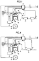
- FIG. 1 is a view showing the overall construction of an embodiment of an internal combustion engine including an exhaust gas purifying apparatus in accordance with the present invention.
- the internal combustion engine in this embodiment is a system mounting an engine 99 of an in-cylinder injection type (or gasoline direct injection type) capable of operation in an oxidizing atmosphere, and comprises an intake air system having an air flow sensor 2, a throttle valve 3 and so on, an exhaust gas system having an oxygen concentration sensor (or an air-to-fuel sensor) 19, an exhaust gas temperature sensor 21, an SOx absorbent 20 and an NOx chemisorption reduction catalyst 23 in accordance with the present invention, a catalyst outlet gas temperature sensor 22 and so on, and a control unit (ECU) 25 and so on.
- the ECU 25 is composed of an I/O LSI as an interface, a microprocessor MPU, memory units ROM and RAM storing a group of control programs, a timer counter and so on.
- Detected signals from a load sensor 8 for detecting an amount of stepping on an accelerator pedal 7, a crank angle sensor 29, the air flow sensor, a water temperature sensor 28, the oxygen concentration sensor (or the air-to-fuel sensor) 19, the exhaust gas temperature sensor 21, the catalyst outlet gas temperature sensor 22 and the like are input to the ECU 25 through an input interface.
- the internal combustion engine described above operates as follows.
- the engine is operated by forming a mixed gas of intake air and fuel by the in-cylinder injection engine 99, gathering the mixed gas around a spark plug 6, and burning the mixed gas just before the time when the piston 9 reaches the top dead point.
- the intake air to the in-cylinder injection engine 99 is filtered by an air cleaner 1, measured by the air flow sensor 2 and supplied to the combustion chamber of the in-cylinder injection engine 99 through the throttle valve 3.
- fuel is supplied from a fuel tank 13 through a fuel pump 12, and injected in the combustion chamber through an injector 5 with a high pressure.
- the ECU 25 determines an operating condition such as an air-to-fuel ratio and so on by evaluating the operating condition of the internal combustion engine and the conditions of the SOx absorbent 20 and the NOx chemisorption reduction catalyst 23 in accordance with the present invention based on each of the sensor signals and the group of pre-stored control programs, and controls the injector 5 and the spark plug 6 and so on to burn the mixed gas under an appropriate condition.
- an operating condition such as an air-to-fuel ratio and so on by evaluating the operating condition of the internal combustion engine and the conditions of the SOx absorbent 20 and the NOx chemisorption reduction catalyst 23 in accordance with the present invention based on each of the sensor signals and the group of pre-stored control programs, and controls the injector 5 and the spark plug 6 and so on to burn the mixed gas under an appropriate condition.
- the ECU 25 controls the air-to-fuel ratio to a fuel lean limit value in order to attain the most economical fuel consumption rate.
- the air-to-fuel ratio exceeds the fuel lean limit value, the combustion condition of the engine 99 is deteriorated to cause an abnormality such as misfiring and to increase fluctuation of generating torque due to decrease in combustion pressure.
- the torque fluctuation causes fluctuation in rotating speed of the engine. Therefore, by predetermining a limit value of the fluctuation in rotating speed, the ECU 25 can control the air-to-fuel ratio or the fuel injection rate so that the rotating speed of the engine obtained from the crank angle sensor 29 is always equal to the limit value. By doing so, the air-to-fuel ratio can be always controlled to the fuel lean limit value without deteriorating the combustion condition of the engine.
- the NOx chemisorption reduction catalyst 23 is arranged downstream of the SOx absorbent 20 in the exhaust gas system.
- SOx in the oxidizing atmosphere exhaust gas is absorbed in the SOx absorbent 20 and NOx is adsorbed in the NOx chemisorption reduction catalyst 23.
- the air-to-fuel ratio is shifted to the fuel rich condition to perform discharging of the absorbed SOx in the SOx absorbent 20 by reduction or purifying of the NOx adsorbed and held during the fuel lean combustion operation. Further, during the fuel rich operation, NOx, HC, CO in the exhaust gas are also cleaned by the three-way catalyst function.
- the NOx in the exhaust gas can be effectively cleaned while the NOx chemisorption reduction catalyst 23 is being prevented from being SOx poisoned under all the combustion conditions of the engine.
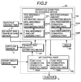
- the ECU 25 comprises an SOx absorbed amount estimating means 101 and an SOx discharged amount estimating means 102 and an air-to-fuel ratio control means 103 and an exhaust gas velocity estimating means 104.
- the SOx absorbed amount estimating means 101 comprises a function for estimating an amount of SOx absorbed in the SOx absorbent (an SOx absorbed amount estimating part) 101A and a function for judging from the estimated value that the cumulated value of the SOx absorbed amount reaches a preset value (an SOx absorbed amount judging part) 101B.
- the SOx discharged amount estimating means 102 comprises (a discharging condition setting part) 102A for estimating a time period required for discharging SOx from the SOx absorbent and operating condition such as an air-to-fuel ratio, and (an SOx discharging condition judging part) 102B for judging that the operating condition reaches an estimated value.
- the air-to-fuel control means 103 comprises a fuel lean combustion operation control part 103A and a fuel rich combustion operation control part 103B.
- the SOx absorbed amount estimating part 101A estimates an amount of SOx absorbed in the SOx absorbent and the SOx absorbed amount judging part 101B judges that the cumulated value of the SOx absorbed amount reaches a preset value
- the fuel rich combustion operation control part 103B of the air-to-fuel control means 103 starts fuel injection amount control of the injector 5 by setting the air-to-fuel ratio so as to produce the reductive atmosphere exhaust gas.
- the discharging condition setting part 102A of the SOx discharged amount estimating means 102 estimates control values (a time period, as an air-to-fuel ratio and the like) required for discharging SOx from the SOx absorbent 20, and the fuel rich combustion operation control part 103B controls based on the estimated values.
- the SOx discharging condition judging part 102B monitors the information of the fuel rich combustion operation control part 103B, and when the SOx discharging condition judging part 102B judges the control value reaches the estimated value, the fuel lean combustion operation control part 103A of the air-to-fuel control means 103 starts fuel injection amount control of the injector 5 by setting the air-to-fuel ratio so as to produce the reductive atmosphere exhaust gas.
- the amount of SOx absorbed to the SOx absorbent under the oxidizing atmosphere and the amount of SOx discharged from the SOx absorbent can be estimated from an gas flow velocity and a fuel consumption rate and an exhaust gas temperature and an operating time period.
- the gas flow velocity can be estimated by the exhaust gas velocity estimating means 104 from an intake air amount and a fuel injection rate and an exhaust gas temperature.
- the information on the fuel consumption rate can be obtained from the air-to-fuel ratio control means 103.
- the exhaust gas temperature can be obtained from the exhaust gas temperature sensor 21, and the intake air amount can be obtained from the air flow sensor 2.
- the operating time period can be measured by a driving time of the injector or by operating a timer 30 during the fuel lean combustion operation.
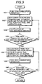
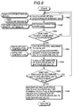
- FIG. 3 is a flow chart showing an embodiment in accordance with the present invention.
- step 1001 when the fuel lean combustion operation (step 1001) is started, based on information of an intake air rate, an exhaust gas temperature, an air-to-fuel ratio or a fuel consumption rate, and an operating time (step 1002), an SOx absorbed amount is calculated by the SOx absorbed amount estimating part 101A (step 1003).
- step 1003 the processing proceeds to step 1004, the SOx absorbed amount judging part 101 judges whether or not the cumulated value of the SOx absorbed amount reaches a predetermined value. If it is judged that the cumulated value of the SOx absorbed amount exceeds the predetermined value, the air-to-fuel ratio control means 103 starts control of the fuel rich combustion operation.
- a fuel rich combustion operating time is calculated by the SOx discharging condition judging part 102B based on the exhaust gas temperature and the intake air rate (step 1005).
- an air-to-fuel ratio during the fuel rich combustion operation is necessary, but here, the air-to-fuel ratio can be fixed to, for example, approximately 13.
- the air-to-fuel ratio control means 103 starts the fuel rich combustion operation (step 1006).
- step 1007 the operating time is monitored, and when the SOx discharging condition judging part 102B judges that the measured value exceeds the calculated value, the processing returns to step 1001 to start the fuel lean combustion operation.
- the NOx chemisorption reduction catalyst 23 can be prevented or suppress to be poisoned with SOx.
- FIG. 4 is an example of a construction of mounting an NOx chemisorption reduction catalyst (18) in a case where the SOx absorbent component and the NOx chemisorption reduction catalyst component are supported in the same support or in a case where the SOx absorbent is coated on the upper layer of the NOx chemisorption reduction catalyst.
- the SOx absorbent and the NOx chemisorption reduction catalyst can be compactly arranged in the exhaust gas passage.
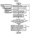
- FIG. 5 is a flow chart showing an embodiment of a means for detecting a stage before the time when sulfurous salts are produced in a catalyst by sulfur poisoning and an amount of sulfuric salts converted from the sulfurous salts reaches a predetermined value.
- step 1002 an amount of SO 2 discharged in the exhaust gas is estimated by calculation from a sulfur concentration in the fuel and a consumption rate of the fuel.
- step 1003 an amount of SO 2 absorbed in the catalyst out of the amount of the discharged SO 2 estimated in step 1002 is estimated by reading the signals such as an exhaust gas temperature and the like, and an amount of sulfurous salts newly produced on the catalyst is estimated.
- step 1003 an amount of sulfuric salts which are to be converted from the sulfurous salt accumulated on the catalyst by heating is estimated. This is because both of the SO 2 absorption rate to the catalyst and the conversion rate from the sulfurous salts to the sulfuric salts are varied depending on temperature.
- the amounts of sulfurous salts and sulfuric salts estimated in step 1004 are respectively cumulated.
- step 1005 it is judged whether or not the cumulated amount of sulfurous salts or sulfuric salts exceeds a predetermined value. If the cumulated amount does not exceed the predetermined value, the processing is repeated from step 1002. If the cumulated amount exceeds the predetermined value, in step 1006 a reductive atmosphere is formed to reduce and decompose the sulfur oxides, and the cumulate of the sulfurous salts and the sulfuric salts are reset.
- FIG. 6 is a flow chart showing another embodiment of a means for detecting a stage before the time when sulfurous salts are produced in a catalyst by sulfur poisoning and an amount of sulfuric salts converted from the sulfurous salts reaches a predetermined value.
- step 1008 an operating condition of the engine is obtained from signals of an oxygen concentration, an A/F and others.
- step 1009 it is judged whether the operating condition of the engine now is lean, stoichiometric or rich operation. If it is lean operation, the processing proceeds to step 1003 to cumulate amounts of sulfurous salts and sulfuric salts. If it is stoichiometric or rich operation, the processing skips the steps below step 1003 to return to step 1002. This is because since the sulfur poisoning particularly strongly occurs during lean operation, accuracy of cumulating amounts of the sulfurous salts and the sulfuric salts is higher in a case of cumulating only during lean operation than in a case of cumulating over the whole operating period.
- FIG. 7 is a flow chart showing another embodiment of a means for detecting a stage before the time when sulfurous salts are produced in a catalyst by sulfur poisoning and an amount of sulfuric salts converted from the sulfurous salts reaches a predetermined value.
- Lean operation is performed in step 1010.
- step 1011 an NOx adsorbing capability of the catalyst is estimated.
- step 1012 it is judged from the NOx adsorbing capability whether or not adsorbed NOx needs to be cleaned by shifting the A/F to a rich condition.
- the A/F is shifted to a rich condition in step 1013, and an elapsing time after the rich shifting is cumulated in step 1014, and completion of the rich shifting is judged in step 1015.
- the A/F is lean shifted in step 1016, and an elapsing time after the lean shifting is cumulated in step 1017.
- step 1018 it is judged whether a predetermined time after the lean shifting elapses or not.
- an NOx purifying rate is estimated using signal from the NOx sensor arranged downstream of the catalyst and so on in step 1019.
- steps 1020 amounts of sulfurous salts and sulfuric salts produced in the catalyst are estimated from the NOx purifying rate estimated.
- step 1021 it is judged whether or not the estimated amount of sulfurous salts or sulfuric salts reaches a predetermined value. If the estimated amount of sulfurous salts or sulfuric salts exceeds the predetermined value, the sulfur oxides are reduced and decomposed by forming a reductive atmosphere in step 1022.
- FIG. 8 shows an example of change of air-to-fuel ratio in operation using a method of recovering a catalyst according to the present invention.
- the sulfurous salts and the sulfuric salts produced in the catalyst by being poisoned by sulfur oxide can be reduced and decomposed with a reductive atmosphere, but this reaction is more difficult to occur compared to the reaction to reducing and purifying NOx adsorbed to an NOx chemisorption reduction catalyst. Therefore, the rich shifting for reducing and decomposing the sulfurous salts and the sulfuric salts needs to be performed for a time period equal to or longer than at least a time period required for the rich shifting for reducing and purifying the NOx adsorbed to the NOx chemisorption reduction catalyst. However, since the fuel economy becomes degraded by performing the rich shifting, the rich shifting should not be kept for a time longer than necessary. As shown in FIG. 8, the rich shifting time is preferably longer than 0.2 second and shorter than 10 minutes.
- an SOx absorbent and an NOx chemisorption reduction catalyst are arranged in an exhaust path of an internal combustion engine, whereby a decrease in NOx purifying capacity of the NOx chemisorption reduction catalyst by absorption or adsorption of SOx can be suppressed.
- the NOx chemisorption reduction catalyst can release SOx by effecting a fuel rich combustion operation or stoichiometric combustion operation even if SOx is absorbed or adsorbed, the NOx purifying capacity can be recovered by estimating an absorption amount or adsorption amount of SOx in the NOx chemisorption reduction catalyst, and operating so as to release SOx when approached to a saturated condition.
Landscapes
- Engineering & Computer Science (AREA)
- Chemical & Material Sciences (AREA)
- Combustion & Propulsion (AREA)
- Mechanical Engineering (AREA)
- General Engineering & Computer Science (AREA)
- Chemical Kinetics & Catalysis (AREA)
- Health & Medical Sciences (AREA)
- Biomedical Technology (AREA)
- Analytical Chemistry (AREA)
- General Chemical & Material Sciences (AREA)
- Oil, Petroleum & Natural Gas (AREA)
- Environmental & Geological Engineering (AREA)
- Toxicology (AREA)
- Exhaust Gas After Treatment (AREA)
Applications Claiming Priority (6)
| Application Number | Priority Date | Filing Date | Title |
|---|---|---|---|
| JP19215897A JP3772478B2 (ja) | 1997-07-17 | 1997-07-17 | 内燃機関の排ガス浄化触媒の再生方法 |
| JP192158/97 | 1997-07-17 | ||
| JP19215897 | 1997-07-17 | ||
| JP23926997 | 1997-09-04 | ||
| JP9239269A JPH1181987A (ja) | 1997-09-04 | 1997-09-04 | NOxの浄化方法 |
| JP239269/97 | 1997-09-04 |
Publications (2)
| Publication Number | Publication Date |
|---|---|
| EP0892159A2 true EP0892159A2 (fr) | 1999-01-20 |
| EP0892159A3 EP0892159A3 (fr) | 2000-04-26 |
Family
ID=26507146
Family Applications (1)
| Application Number | Title | Priority Date | Filing Date |
|---|---|---|---|
| EP98113113A Withdrawn EP0892159A3 (fr) | 1997-07-17 | 1998-07-14 | Dispositif et procédé d' épuration de gaz d' échappement pour moteurs à combustion interne |
Country Status (4)
| Country | Link |
|---|---|
| US (1) | US6272848B1 (fr) |
| EP (1) | EP0892159A3 (fr) |
| KR (1) | KR100481904B1 (fr) |
| CN (1) | CN1103857C (fr) |
Cited By (10)
| Publication number | Priority date | Publication date | Assignee | Title |
|---|---|---|---|---|
| WO2000068551A1 (fr) * | 1999-05-05 | 2000-11-16 | Ford Global Technologies, Inc. | Systeme de gestion d'un moteur |
| EP1080783A2 (fr) * | 1999-09-02 | 2001-03-07 | Toyota Jidosha Kabushiki Kaisha | Catalyseur multi-couches pour l'épuration des gaz d'échappement |
| EP1083306A1 (fr) * | 1999-09-07 | 2001-03-14 | MAGNETI MARELLI S.p.A. | Procédé de controle auto-adaptive pour un systeme d'échappement d'un moteur à combustion interne |
| EP1147802A1 (fr) * | 2000-04-10 | 2001-10-24 | Kemira Metalkat Oy | Adsorbent-catalyseur |
| EP1026374A3 (fr) * | 1999-02-08 | 2002-03-20 | Mazda Motor Corporation | Dispositif de purification de gaz d'échappement pour un moteur à combustion interne |
| EP1030043A3 (fr) * | 1999-02-16 | 2003-02-12 | Nissan Motor Company, Limited | Dispositif de purification de gaz d'échappement pour un moteur |
| WO2003018178A1 (fr) * | 2001-08-24 | 2003-03-06 | Engelhard Corporation | Catalyseur monobloc a piege a sox et ses procedes de fabrication et d'utilisation |
| EP1867381A1 (fr) * | 2005-03-29 | 2007-12-19 | Yanmar Co., Ltd. | Purificateur de gaz d echappement |
| WO2009056958A1 (fr) * | 2007-11-02 | 2009-05-07 | Toyota Jidosha Kabushiki Kaisha | Dispositif d'épuration de gaz d'échappement pour moteur à combustion interne |
| CN109126408A (zh) * | 2018-08-23 | 2019-01-04 | 南京天创电子技术有限公司 | 一种湿法脱硫装置及智能控制方法 |
Families Citing this family (42)
| Publication number | Priority date | Publication date | Assignee | Title |
|---|---|---|---|---|
| KR100580448B1 (ko) * | 1999-12-30 | 2006-05-15 | 현대자동차주식회사 | Obd-ⅱ용 스레스홀드 촉매의 제조방법 |
| FR2805174B1 (fr) * | 2000-02-22 | 2002-05-03 | Inst Francais Du Petrole | Procede et dispositif pour controler la regeneration par combustion, d'un filtre retenant des particules |
| US6487849B1 (en) * | 2000-03-17 | 2002-12-03 | Ford Global Technologies, Inc. | Method and apparatus for controlling lean-burn engine based upon predicted performance impact and trap efficiency |
| US6901749B2 (en) * | 2000-08-01 | 2005-06-07 | Honda Giken Kogyo Kabushiki Kaisha | Exhaust emission control system for internal combustion engine |
| WO2002022239A1 (fr) * | 2000-09-12 | 2002-03-21 | Emerachem Llc | Elimination d'oxydes de soufre des gaz d'echappement provenant de processus de combustion |
| US7021049B2 (en) * | 2000-09-29 | 2006-04-04 | Ford Global Technologies, Llc | Vehicle sulfur oxide trap and related method |
| US6758036B1 (en) * | 2000-10-27 | 2004-07-06 | Delphi Technologies, Inc. | Method for sulfur protection of NOx adsorber |
| US20020107139A1 (en) * | 2000-12-05 | 2002-08-08 | Degnan Thomas F. | Encapsulated hydrogenation catalysts with controlled dispersion and activity |
| JP3711329B2 (ja) * | 2001-02-01 | 2005-11-02 | ミヤマ株式会社 | 車両運転状態評価システム |
| US6832473B2 (en) * | 2002-11-21 | 2004-12-21 | Delphi Technologies, Inc. | Method and system for regenerating NOx adsorbers and/or particulate filters |
| JP4092486B2 (ja) * | 2003-04-02 | 2008-05-28 | 日産自動車株式会社 | 内燃機関の排気後処理装置の診断装置 |
| JP4349119B2 (ja) * | 2003-12-19 | 2009-10-21 | いすゞ自動車株式会社 | 排気ガス浄化方法及び排気ガス浄化システム |
| JP4543689B2 (ja) * | 2004-02-02 | 2010-09-15 | トヨタ自動車株式会社 | 排気浄化触媒 |
| US7767163B2 (en) * | 2004-04-20 | 2010-08-03 | Umicore Ag & Co. Kg | Exhaust treatment devices |
| JP4192905B2 (ja) | 2005-03-04 | 2008-12-10 | トヨタ自動車株式会社 | 内燃機関の排気浄化装置 |
| US7389638B2 (en) * | 2005-07-12 | 2008-06-24 | Exxonmobil Research And Engineering Company | Sulfur oxide/nitrogen oxide trap system and method for the protection of nitrogen oxide storage reduction catalyst from sulfur poisoning |
| US7435275B2 (en) * | 2005-08-11 | 2008-10-14 | Delphi Technologies, Inc. | System and method of heating an exhaust treatment device |
| US20070084116A1 (en) * | 2005-10-13 | 2007-04-19 | Bayerische Motoren Werke Aktiengesellschaft | Reformer system having electrical heating devices |
| JP5157068B2 (ja) * | 2006-01-10 | 2013-03-06 | トヨタ自動車株式会社 | 硫化水素生成抑制材及び排ガス浄化用触媒 |
| JP5582671B2 (ja) * | 2006-04-21 | 2014-09-03 | 株式会社キャタラー | 排ガス浄化用触媒、排ガス浄化用触媒の回復方法、及び排ガス浄化用触媒システム |
| DE602007004039D1 (de) * | 2006-08-01 | 2010-02-11 | Honda Motor Co Ltd | Schwefelreinigungssteuerungsvorrichtung für einen Verbrennungsmotor |
| US7654079B2 (en) | 2006-11-07 | 2010-02-02 | Cummins, Inc. | Diesel oxidation catalyst filter heating system |
| US7533523B2 (en) * | 2006-11-07 | 2009-05-19 | Cummins, Inc. | Optimized desulfation trigger control for an adsorber |
| US7654076B2 (en) * | 2006-11-07 | 2010-02-02 | Cummins, Inc. | System for controlling absorber regeneration |
| US7707826B2 (en) | 2006-11-07 | 2010-05-04 | Cummins, Inc. | System for controlling triggering of adsorber regeneration |
| US7594392B2 (en) * | 2006-11-07 | 2009-09-29 | Cummins, Inc. | System for controlling adsorber regeneration |
| JP4656065B2 (ja) * | 2007-02-06 | 2011-03-23 | トヨタ自動車株式会社 | 内燃機関の排気浄化装置 |
| JP4665914B2 (ja) * | 2007-02-23 | 2011-04-06 | トヨタ自動車株式会社 | 内燃機関の排気浄化装置 |
| JP4793316B2 (ja) * | 2007-04-20 | 2011-10-12 | トヨタ自動車株式会社 | 硫黄吸蔵触媒 |
| JP4710872B2 (ja) * | 2007-05-16 | 2011-06-29 | トヨタ自動車株式会社 | 内燃機関の排気浄化装置 |
| DE102007050272A1 (de) * | 2007-10-18 | 2009-04-23 | Robert Bosch Gmbh | Tank zur Bevorratung eines Reduktionsmittels |
| JP5422215B2 (ja) * | 2009-01-30 | 2014-02-19 | 三菱重工業株式会社 | 排ガス浄化装置 |
| WO2010128562A1 (fr) * | 2009-05-07 | 2010-11-11 | トヨタ自動車株式会社 | Dispositif de purification de gaz d'échappement pour moteur à combustion interne |
| EP2505997B1 (fr) * | 2009-11-26 | 2015-10-21 | Toyota Jidosha Kabushiki Kaisha | Appareil de détection de composants soufrés |
| US20110185708A1 (en) * | 2010-01-29 | 2011-08-04 | Eaton Corporation | Adaptive Desulfation Control Algorithm |
| DE102013017230B4 (de) * | 2013-10-17 | 2021-12-23 | Man Energy Solutions Se | Verfahren zur Desulfatierung eines Abgasnachbehandlungssystem einer Brennkraftmaschine |
| JP6036786B2 (ja) * | 2014-10-17 | 2016-11-30 | トヨタ自動車株式会社 | 内燃機関の硫黄濃度判定システム |
| JP6179505B2 (ja) * | 2014-12-24 | 2017-08-16 | トヨタ自動車株式会社 | 内燃機関の排気浄化システム |
| WO2016175737A1 (fr) * | 2015-04-27 | 2016-11-03 | Cummins Emission Solutions, Inc. | Catalyseur d'oxydation bicouche destiné à améliorer le rendement de soufre |
| JP6550996B2 (ja) * | 2015-07-16 | 2019-07-31 | いすゞ自動車株式会社 | 吸蔵量推定装置 |
| US11085848B2 (en) * | 2019-09-04 | 2021-08-10 | GM Global Technology Operations LLC | Method of estimating oxygen storage capacity of catalyst |
| CN111167274B (zh) * | 2020-01-19 | 2021-11-12 | 中南大学 | 一种从冶炼烟气中脱除三氧化硫的方法及其脱除装置 |
Citations (8)
| Publication number | Priority date | Publication date | Assignee | Title |
|---|---|---|---|---|
| WO1993008383A1 (fr) * | 1991-10-14 | 1993-04-29 | Toyota Jidosha Kabushiki Kaisha | Dispositif d'echappement et d'epuration pour moteurs a combustion interne |
| EP0625633A1 (fr) * | 1992-12-03 | 1994-11-23 | Toyota Jidosha Kabushiki Kaisha | Epurateur de gaz d'echappement pour moteurs a combustion interne |
| JPH07155601A (ja) * | 1993-10-14 | 1995-06-20 | Toyota Motor Corp | 排気ガス浄化用触媒 |
| US5451558A (en) * | 1994-02-04 | 1995-09-19 | Goal Line Environmental Technologies | Process for the reaction and absorption of gaseous air pollutants, apparatus therefor and method of making the same |
| DE19522165A1 (de) * | 1994-06-17 | 1995-12-21 | Mitsubishi Motors Corp | Vorrichtung und Verfahren für die Regelung einer Verbrennungskraftmaschine |
| JPH08259344A (ja) * | 1995-03-28 | 1996-10-08 | Matsushita Electric Works Ltd | 多孔性吸着体 |
| JPH0988560A (ja) * | 1995-09-27 | 1997-03-31 | Nissan Motor Co Ltd | エンジンの診断装置 |
| EP0814242A1 (fr) * | 1996-06-20 | 1997-12-29 | Johnson Matthey Public Limited Company | Lutte contre la pollution atmosphérique |
Family Cites Families (11)
| Publication number | Priority date | Publication date | Assignee | Title |
|---|---|---|---|---|
| US5116800A (en) * | 1990-12-11 | 1992-05-26 | Allied-Signal Inc. | High durability and exhuast catalyst with low hydrogen sulfide emissions |
| US5134108A (en) * | 1991-05-22 | 1992-07-28 | Engelhard Corporation | Process for preparing catalyst with copper or zinc and with chromium, molybdenum, tungsten, or vanadium, and product thereof |
| JP2605586B2 (ja) * | 1992-07-24 | 1997-04-30 | トヨタ自動車株式会社 | 内燃機関の排気浄化装置 |
| EP0664147B1 (fr) * | 1994-01-20 | 1998-07-22 | Toyota Jidosha Kabushiki Kaisha | Catalyseur pour la purification de gaz d'échappement |
| JP3544400B2 (ja) | 1995-01-13 | 2004-07-21 | 株式会社豊田中央研究所 | 排ガス浄化用触媒 |
| US5911961A (en) * | 1994-12-06 | 1999-06-15 | Ict Co., Ltd. | Catalyst for purification of diesel engine exhaust gas |
| US5750082A (en) * | 1995-09-21 | 1998-05-12 | Ford Global Technologies, Inc. | Nox trap with improved performance |
| JPH09155191A (ja) | 1995-10-06 | 1997-06-17 | Toyota Central Res & Dev Lab Inc | 排ガス浄化用触媒及びその製造方法 |
| DE19543219C1 (de) * | 1995-11-20 | 1996-12-05 | Daimler Benz Ag | Verfahren zum Betreiben eines Dieselmotors |
| US5758489A (en) * | 1996-06-13 | 1998-06-02 | Ford Global Technologies, Inc. | Sulfur tolerant Pt/lithium NOx traps |
| JPH1071325A (ja) * | 1996-06-21 | 1998-03-17 | Ngk Insulators Ltd | エンジン排ガス系の制御方法および触媒/吸着手段の劣化検出方法 |
-
1998
- 1998-07-14 EP EP98113113A patent/EP0892159A3/fr not_active Withdrawn
- 1998-07-16 KR KR10-1998-0028890A patent/KR100481904B1/ko not_active IP Right Cessation
- 1998-07-17 CN CN98116130A patent/CN1103857C/zh not_active Expired - Fee Related
- 1998-07-17 US US09/116,708 patent/US6272848B1/en not_active Expired - Fee Related
Patent Citations (8)
| Publication number | Priority date | Publication date | Assignee | Title |
|---|---|---|---|---|
| WO1993008383A1 (fr) * | 1991-10-14 | 1993-04-29 | Toyota Jidosha Kabushiki Kaisha | Dispositif d'echappement et d'epuration pour moteurs a combustion interne |
| EP0625633A1 (fr) * | 1992-12-03 | 1994-11-23 | Toyota Jidosha Kabushiki Kaisha | Epurateur de gaz d'echappement pour moteurs a combustion interne |
| JPH07155601A (ja) * | 1993-10-14 | 1995-06-20 | Toyota Motor Corp | 排気ガス浄化用触媒 |
| US5451558A (en) * | 1994-02-04 | 1995-09-19 | Goal Line Environmental Technologies | Process for the reaction and absorption of gaseous air pollutants, apparatus therefor and method of making the same |
| DE19522165A1 (de) * | 1994-06-17 | 1995-12-21 | Mitsubishi Motors Corp | Vorrichtung und Verfahren für die Regelung einer Verbrennungskraftmaschine |
| JPH08259344A (ja) * | 1995-03-28 | 1996-10-08 | Matsushita Electric Works Ltd | 多孔性吸着体 |
| JPH0988560A (ja) * | 1995-09-27 | 1997-03-31 | Nissan Motor Co Ltd | エンジンの診断装置 |
| EP0814242A1 (fr) * | 1996-06-20 | 1997-12-29 | Johnson Matthey Public Limited Company | Lutte contre la pollution atmosphérique |
Non-Patent Citations (3)
| Title |
|---|
| PATENT ABSTRACTS OF JAPAN vol. 1995, no. -Ÿ, 31 October 1995 (1995-10-31) & JP 07 155601 A (TOYOTA MOTOR CORP), 20 June 1995 (1995-06-20) * |
| PATENT ABSTRACTS OF JAPAN vol. 1997, no. 07, 31 July 1997 (1997-07-31) & JP 09 088560 A (NISSAN MOTOR CO LTD), 31 March 1997 (1997-03-31) * |
| PATENT ABSTRACTS OF JAPAN vol. 1997, no. -Ÿ, 28 February 1997 (1997-02-28) & JP 08 259344 A (MATSUSHITA ELECTRIC WORKS LTD), 8 October 1996 (1996-10-08) * |
Cited By (15)
| Publication number | Priority date | Publication date | Assignee | Title |
|---|---|---|---|---|
| EP1026374A3 (fr) * | 1999-02-08 | 2002-03-20 | Mazda Motor Corporation | Dispositif de purification de gaz d'échappement pour un moteur à combustion interne |
| EP1030043A3 (fr) * | 1999-02-16 | 2003-02-12 | Nissan Motor Company, Limited | Dispositif de purification de gaz d'échappement pour un moteur |
| WO2000068551A1 (fr) * | 1999-05-05 | 2000-11-16 | Ford Global Technologies, Inc. | Systeme de gestion d'un moteur |
| EP1080783A2 (fr) * | 1999-09-02 | 2001-03-07 | Toyota Jidosha Kabushiki Kaisha | Catalyseur multi-couches pour l'épuration des gaz d'échappement |
| EP1080783A3 (fr) * | 1999-09-02 | 2002-06-26 | Toyota Jidosha Kabushiki Kaisha | Catalyseur multi-couches pour l'épuration des gaz d'échappement |
| EP1083306A1 (fr) * | 1999-09-07 | 2001-03-14 | MAGNETI MARELLI S.p.A. | Procédé de controle auto-adaptive pour un systeme d'échappement d'un moteur à combustion interne |
| US6327848B1 (en) | 1999-09-07 | 2001-12-11 | Magneti Marelli S.P.A | Self-adapting control method for an exhaust system for internal combustion engines with controlled ignition |
| EP1147802A1 (fr) * | 2000-04-10 | 2001-10-24 | Kemira Metalkat Oy | Adsorbent-catalyseur |
| US6818582B2 (en) | 2000-04-10 | 2004-11-16 | Kemira Metalkat Oy | Adsorbent catalyst |
| WO2003018178A1 (fr) * | 2001-08-24 | 2003-03-06 | Engelhard Corporation | Catalyseur monobloc a piege a sox et ses procedes de fabrication et d'utilisation |
| EP1867381A1 (fr) * | 2005-03-29 | 2007-12-19 | Yanmar Co., Ltd. | Purificateur de gaz d echappement |
| EP1867381A4 (fr) * | 2005-03-29 | 2010-05-26 | Yanmar Co Ltd | Purificateur de gaz d echappement |
| WO2009056958A1 (fr) * | 2007-11-02 | 2009-05-07 | Toyota Jidosha Kabushiki Kaisha | Dispositif d'épuration de gaz d'échappement pour moteur à combustion interne |
| CN109126408A (zh) * | 2018-08-23 | 2019-01-04 | 南京天创电子技术有限公司 | 一种湿法脱硫装置及智能控制方法 |
| CN109126408B (zh) * | 2018-08-23 | 2024-04-16 | 南京天创电子技术有限公司 | 一种湿法脱硫装置及智能控制方法 |
Also Published As
| Publication number | Publication date |
|---|---|
| CN1206070A (zh) | 1999-01-27 |
| CN1103857C (zh) | 2003-03-26 |
| US6272848B1 (en) | 2001-08-14 |
| EP0892159A3 (fr) | 2000-04-26 |
| KR100481904B1 (ko) | 2005-06-08 |
| KR19990013960A (ko) | 1999-02-25 |
Similar Documents
| Publication | Publication Date | Title |
|---|---|---|
| US6272848B1 (en) | Exhaust gas cleaning apparatus and method for internal combustion engine | |
| US6397582B1 (en) | Exhaust gas purification apparatus of internal combustion engine and catalyst for purifying exhaust gas of internal combustion engine | |
| KR20010052088A (ko) | 내연기관의 배기가스 정화장치, 배기가스정화방법 및배기가스정화촉매 | |
| JP4415989B2 (ja) | 内燃機関の排ガス浄化装置、排ガス浄化方法、及び内燃機関用s分捕捉材 | |
| JP2001050036A (ja) | 排気浄化制御装置 | |
| KR20000053474A (ko) | 내연기관의 배기가스 정화방법,배기가스 정화촉매 및배기가스 정화장치 | |
| US8689546B2 (en) | Exhaust purification system of internal combustion engine | |
| JP3772478B2 (ja) | 内燃機関の排ガス浄化触媒の再生方法 | |
| JP4147702B2 (ja) | 内燃機関の排ガス浄化用NOx吸着触媒 | |
| JP4333612B2 (ja) | 排ガスの浄化装置および排ガス浄化触媒 | |
| EP2581576B1 (fr) | Système d'épuration des gaz d'échappement pour moteur à combustion interne | |
| JP3896224B2 (ja) | 内燃機関の制御装置 | |
| JPH1181987A (ja) | NOxの浄化方法 | |
| JP3107303B2 (ja) | 内燃機関の排ガス浄化装置 | |
| JP2004028041A (ja) | 排気ガス浄化システム及び排気ガス浄化方法 | |
| AU742434B2 (en) | Exhaust gas purification apparatus of internal combustion engine and catalyst for purifying exhaust gas of internal combustion engine | |
| JPH11114377A (ja) | 内燃機関排ガスの浄化方法及び触媒 | |
| JP2001259415A (ja) | 窒素酸化物吸脱着材及び排気ガス浄化システム |
Legal Events
| Date | Code | Title | Description |
|---|---|---|---|
| PUAI | Public reference made under article 153(3) epc to a published international application that has entered the european phase |
Free format text: ORIGINAL CODE: 0009012 |
|
| AK | Designated contracting states |
Kind code of ref document: A2 Designated state(s): DE FR GB IT |
|
| AX | Request for extension of the european patent |
Free format text: AL;LT;LV;MK;RO;SI |
|
| RIC1 | Information provided on ipc code assigned before grant |
Free format text: 6F 02D 41/02 A, 6B 01D 53/94 B, 6F 01N 3/08 B |
|
| PUAL | Search report despatched |
Free format text: ORIGINAL CODE: 0009013 |
|
| AK | Designated contracting states |
Kind code of ref document: A3 Designated state(s): AT BE CH CY DE DK ES FI FR GB GR IE IT LI LU MC NL PT SE |
|
| AX | Request for extension of the european patent |
Free format text: AL;LT;LV;MK;RO;SI |
|
| 17P | Request for examination filed |
Effective date: 20000831 |
|
| AKX | Designation fees paid |
Free format text: DE FR GB IT |
|
| 17Q | First examination report despatched |
Effective date: 20020912 |
|
| GRAP | Despatch of communication of intention to grant a patent |
Free format text: ORIGINAL CODE: EPIDOSNIGR1 |
|
| STAA | Information on the status of an ep patent application or granted ep patent |
Free format text: STATUS: THE APPLICATION IS DEEMED TO BE WITHDRAWN |
|
| 18D | Application deemed to be withdrawn |
Effective date: 20060923 |