EP0876893B1 - Vorrichtung zum Spritzgiessen von Kunststoffteilen - Google Patents
Vorrichtung zum Spritzgiessen von Kunststoffteilen Download PDFInfo
- Publication number
- EP0876893B1 EP0876893B1 EP98104450A EP98104450A EP0876893B1 EP 0876893 B1 EP0876893 B1 EP 0876893B1 EP 98104450 A EP98104450 A EP 98104450A EP 98104450 A EP98104450 A EP 98104450A EP 0876893 B1 EP0876893 B1 EP 0876893B1
- Authority
- EP
- European Patent Office
- Prior art keywords
- edge
- sealing
- workpiece
- mouldings
- moulding
- Prior art date
- Legal status (The legal status is an assumption and is not a legal conclusion. Google has not performed a legal analysis and makes no representation as to the accuracy of the status listed.)
- Expired - Lifetime
Links
- 239000004033 plastic Substances 0.000 title claims description 14
- 238000001746 injection moulding Methods 0.000 title claims description 13
- 238000000034 method Methods 0.000 title description 4
- 238000007789 sealing Methods 0.000 claims description 83
- 238000002347 injection Methods 0.000 claims description 33
- 239000007924 injection Substances 0.000 claims description 33
- 238000000465 moulding Methods 0.000 claims description 30
- 239000011521 glass Substances 0.000 claims description 24
- 125000006850 spacer group Chemical group 0.000 claims description 6
- 239000000463 material Substances 0.000 claims description 5
- 238000009966 trimming Methods 0.000 claims description 3
- 239000004413 injection moulding compound Substances 0.000 claims 2
- 230000035515 penetration Effects 0.000 claims 1
- 239000013589 supplement Substances 0.000 claims 1
- 150000001875 compounds Chemical class 0.000 description 12
- 239000007921 spray Substances 0.000 description 10
- 238000005507 spraying Methods 0.000 description 4
- 238000004519 manufacturing process Methods 0.000 description 3
- 230000006978 adaptation Effects 0.000 description 2
- 238000005538 encapsulation Methods 0.000 description 2
- 239000002023 wood Substances 0.000 description 2
- 229910000831 Steel Inorganic materials 0.000 description 1
- 230000004888 barrier function Effects 0.000 description 1
- 239000007795 chemical reaction product Substances 0.000 description 1
- 238000005520 cutting process Methods 0.000 description 1
- 238000007688 edging Methods 0.000 description 1
- 230000000694 effects Effects 0.000 description 1
- 238000005516 engineering process Methods 0.000 description 1
- 239000012530 fluid Substances 0.000 description 1
- -1 for example Substances 0.000 description 1
- 238000009957 hemming Methods 0.000 description 1
- 239000002184 metal Substances 0.000 description 1
- 239000002991 molded plastic Substances 0.000 description 1
- 238000005192 partition Methods 0.000 description 1
- 230000002093 peripheral effect Effects 0.000 description 1
- 238000012805 post-processing Methods 0.000 description 1
- 238000003825 pressing Methods 0.000 description 1
- 238000012545 processing Methods 0.000 description 1
- 239000012858 resilient material Substances 0.000 description 1
- 239000000243 solution Substances 0.000 description 1
- 239000010959 steel Substances 0.000 description 1
Images



Classifications
-
- B—PERFORMING OPERATIONS; TRANSPORTING
- B29—WORKING OF PLASTICS; WORKING OF SUBSTANCES IN A PLASTIC STATE IN GENERAL
- B29C—SHAPING OR JOINING OF PLASTICS; SHAPING OF MATERIAL IN A PLASTIC STATE, NOT OTHERWISE PROVIDED FOR; AFTER-TREATMENT OF THE SHAPED PRODUCTS, e.g. REPAIRING
- B29C45/00—Injection moulding, i.e. forcing the required volume of moulding material through a nozzle into a closed mould; Apparatus therefor
- B29C45/14—Injection moulding, i.e. forcing the required volume of moulding material through a nozzle into a closed mould; Apparatus therefor incorporating preformed parts or layers, e.g. injection moulding around inserts or for coating articles
- B29C45/14336—Coating a portion of the article, e.g. the edge of the article
- B29C45/14418—Sealing means between mould and article
-
- B—PERFORMING OPERATIONS; TRANSPORTING
- B29—WORKING OF PLASTICS; WORKING OF SUBSTANCES IN A PLASTIC STATE IN GENERAL
- B29C—SHAPING OR JOINING OF PLASTICS; SHAPING OF MATERIAL IN A PLASTIC STATE, NOT OTHERWISE PROVIDED FOR; AFTER-TREATMENT OF THE SHAPED PRODUCTS, e.g. REPAIRING
- B29C45/00—Injection moulding, i.e. forcing the required volume of moulding material through a nozzle into a closed mould; Apparatus therefor
- B29C45/17—Component parts, details or accessories; Auxiliary operations
- B29C45/26—Moulds
- B29C45/2608—Mould seals
Definitions
- the Moldings have dividers that run towards each other and at closed injection mold to form sealing edges Face the workpiece so that a sealed recess for Injection molding of the skirt is formed, finally the sealing edges of the Molded parts thanks to spring-elastic elements formed and parallel to the closing direction of the Moldings of the injection mold adjustable are.
- EP A 0 401 091 is also a device for an injection mold known, with a workpiece in the Injection mold is insertable, at the Edging made of plastic is injected and that for injection molding the sealing edges provided through one in the designated chambers located, adjustable pressure fluid are formed and thus sealing against the Workpiece to be pressed.
- DE 32 27 014 A1 is a Device for pressure spraying a Known edge protection made of plastic, being in the injection mold for example a plate made of wood-based materials inserted will and for sealing the mold space Plate towards sealing strips made of steel are provided in the mold halves are limitedly displaceable and under the action of an elastic pressing force stand.
- JP-A-57 193 334, JP-A-07 156 193, JP-A-03 292 120, DE-A-35 32 424, WO-A-87 04 973 and EP-A-0 127 546 are others Generic devices known.
- each resilient element by a Push belt is formed, the one Variety of essentially transverse to Longitudinal course of the closing direction of the Moldings adjustable sealing edge directed, immediately adjacent, has dimensionally stable rod elements, which in a Backing layer made of flexible material used or held by this, the carrier layer on which the sealing edge supporting molded part is fixed, and that the Distance between adjacent bar elements of the push link belt is so low that prevents the inflow of spray compound is.
- the adjusting means through between the sealing edge and the it load-bearing molded part screwed Set screws are formed.
- the viscosity of the spray compound is usually not so big that a Flow of spray compound into the gap between the neighboring finger-like Spring elements are to be expected. In each Case the gap can be made so small be an inflow of spray compound is prevented. Freezes during the spraying process the molding compound in the mold like this quickly that an inflow of No injection compound into the slots anyway is to be expected.
- a particularly preferred training is seen in the fact that the sealing edges partially or completely parallel to Closing direction of the molded parts Injection mold are resilient.
- the seal in the area of the sealing webs takes place on the glass pane or on the Workpiece through a relatively narrow edge the resilient sealing edge, see above that an effective seal barrier between the inner freedom and the outer Form recesses are created.
- the sealing edge is made of rigid thermally highly resilient material, for example, metal, are in in practice, extremely long service life reached.
- the on its edge encapsulating disc or the like one versus the entire area of the Disk very small area sufficient firmly clamped. Because the sealing edge is springy compliant is sufficient Assured mobility so that when Closing the molded parts an automatic Adaptation to different Disc curvatures and contours. This will result in the risk of breaking panes strong during the production process diminishes and thus the economy noticeable in such mass production elevated.
- both sides of the glass pane or the Workpiece between the corresponding Molding and the glass pane or the Workpiece a resilient Sealing edge, partially or completely all around, is arranged.
- the resilient sealing edge can be formed from several individual elements, leaving the corner areas free and are formed by rigid sealing edges, that from the material of the molded parts consist.
- adjustable sealing edge arrangement can the resilient sealing edges in a simple way to make an adjustment for example by underlaying Spacer bars or set screws Tolerance compensation is made.
- edge or glass pane as orthogonal separating edge or cutting edge is designed without trimming.
- FIGS. 5 to 9 are not part of the invention, in particular no embodiments of the invention.
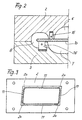
- FIG. 1 is schematic a device for injection molding Plastic parts shown. It consists of an injection mold 1 with two molded parts 2.3 (mold halves in the exemplary embodiment).
- the injection mold 1 has at least one Inlet opening 14 for spray compound.
- the Moldings 2,3 have sealing edges that in the area of the closing surfaces 4.5 in generally without a liner Gasket pressed against each other. There is at least one of the two Closing surfaces 4 or 5 often with one molded sealing edge formed.
- the Mold halves 2,3 each have approximately in the Free spaces 6,7 in the mold as well a circumferential recess 8 on the the free spaces 6,7 by two Recess 8 delimiting, against each other directional, circumferential sealing webs 9 are limited. The spacing of the sealing webs 9 are designed so that between them a disc 10 is inserted tightly.
- the sealing webs 9 Sealing edges on either only in Partial areas or even over their entire are adjustable. Training such a seal is shown in Figure 5 to 7 explained in more detail using an example.
- a sealing web sealing web 9 in the form of a rigid sealing edge above the disc 10 formed on the Disc 10 is present during the corresponding sealing web on the underside of the Washer 10 through a sealing edge 11 is formed, which is parallel to Closing direction of the molded parts 2,3 is adjustable.
- the sealing edge 11 is thereby by resilient elements 12 formed, for example, by Documents or means of positioning relative to Parting plane of the molded part 3 adjustable and are noticeable. According to the The embodiment according to FIG.
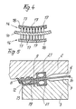
- a Push link belt 16 can spring elastic element by a Push link belt 16 be formed, which in essentially transverse to the longitudinal course of the Sealing edge directed dimensionally rigid Bar elements 17, which in a Backing layer 18 made of flexible material, for example rubber used by these are held, the Carrier layer 18 on which the sealing edge supporting molded part 2 or 3 is fixed.
- the resilient Element 12 formed by a leaf spring, the base 19 on which the sealing edge 11 load-bearing molding, such as the Molding 3, is fixed and from its base 19 finger-like isolated spring elements 12 protrude in the same direction.
- the distance between the neighboring ones Rod element 17 of the push link belt 16 or the finger-like spring elements 12 of the Leaf spring is so low that a Influence of spray compound excluded is.
- resilient element 12 While in the embodiment for example according to FIGS. 5 to 7 resilient element 12 is fixed, thus when the disc 10 is placed for example, cannot spring or the Travel is at least rigidly limited in the embodiment, for example Figure 8 and 9 and also in training according to Figures 2 and 4, the sealing edge resilient yielding.
- Positioning means 21 provided in a starting position in the Drawing figures is shown in which the molded parts 2, 3 of the injection mold 1 Closing the shape are approximated and the sealing edges 9 and 11 respectively the glass pane 10 or the workpiece apply, distance from the glass pane 10 or have the workpiece.
- This training will improve a secure, yet soft holder of the Glass pane 10 in the mold 1 guaranteed, due to this Arrangement of the peripheral edge of the Glass panel 10, for example, not trimmed must be, but it can only be through be a separating cut, the orthogonal to the area extension of the Glass pane 10 runs.
- the Positioning means 21 ensures that the edge of the glass sheet 10 not against stationary stops or the like pressed and by trimming the Glass pane 10 no longer required is, the end product can be cheaper are manufactured.
Landscapes
- Engineering & Computer Science (AREA)
- Manufacturing & Machinery (AREA)
- Mechanical Engineering (AREA)
- Moulds For Moulding Plastics Or The Like (AREA)
- Injection Moulding Of Plastics Or The Like (AREA)
Description
Es zeigt:
- Figur 1
- eine Spritzgießvorrichtung im Querschnitt bei geschlossenen Formteilen;
- Figur 2
- einen Ausschnitt in vergrößerter Darstellung;
- Figur 3
- ein Formteil der Gießform in Ansicht;
- Figur 4
- eine Einzelheit in vergrößerter Darstellung;
- Figur 5-7
- weitere Einzelheiten in vergrößerter Darstellung;
- Figur 8 und 9
- eine weitere Einzelheit in der Ansicht gemäß Figur 5 und 7.
Claims (10)
- Vorrichtung zum Spritzgießen von Kunststoffteilen, bestehend aus einer aus wenigstens zwei Formteilen (2,3), gebildeten Spritzgießform (1) mit mindestens einer Einlaßöffnung (14) für Spritzmasse, wobei die Formteile (2,3) Dichtkanten aufweisen, die bei geschlossener Spritzgießform (1) dicht aneinander anliegen oder dicht an einer Gegenfläche des jeweils anderen Formteiles (2,3) anliegen, wobei ferner in die Spritzgießform (1) ein Werkstück, z.B. eine Glasscheibe (10), einlegbar ist, an das oder an dessen Rand eine Einfassung aus Kunststoff angespritzt wird, wobei die Formteile (2,3) Trennstege aufweisen, die zueinander hin gerichtet verlaufen und bei geschlossener Spritzgießform (1) unter Ausbildung von Dichtkanten (11) dichtend an Flächen des Werkstückes anliegen, so dass eine abgedichtete Ausnehmung (8) zur Spritzformung der Einfassung gebildet ist, wobei schließlich die Dichtkanten (11) der Formteile (2,3) durch federelastische Elemente gebildet und parallel zur Schließrichtung der Formteile (2,3) der Spritzgießform einstellbar sind, dadurch gekennzeichnet, dass jedes federelastische Element durch ein Schubgliederband (16) gebildet ist, das eine Vielzahl von im Wesentlichen quer zum Längsverlauf der zur Schließrichtung der Formteile (2,3) einstellbaren Dichtkante (11) gerichtete, unmittelbar benachbarte, formsteife Stabelemente (17) aufweist, die in eine Trägerschicht (18) aus flexiblem Material eingesetzt oder von dieser gehalten sind, wobei die Trägerschicht (18) an dem die Dichtkante (11) tragenden Formteil (2 oder 3) fixiert ist, und dass der Abstand zueinander benachbarter Stabelemente (17) des Schubgliederbandes (16) so gering ist, dass ein Einfließen von Spritzmasse verhindert ist.
- Vorrichtung nach Anspruch 1, dadurch gekennzeichnet, dass die federelastischen Elemente (12) mittels Unterlagen oder durch Stellmittel relativ zur Trennebene des Formteiles (2 oder 3) verstellbar und feststellbar sind.
- Vorrichtung nach Anspruch 1 oder 2, dadurch gekennzeichnet, dass die Unterlagen durch zwischen der Dichtkante (11) und dem sie tragenden Formteil (2 oder 3) angeordnete Distanzleisten gebildet sind.
- Vorrichtung nach Anspruch 1 oder 2, dadurch gekennzeichnet, dass die Unterlagen durch zwischen die Dichtkante (11) und das sie tragende Formteil (2 oder 3) eingeschobene Distanzkeile (13) gebildet sind.
- Vorrichtung nach Anspruch 2, dadurch gekennzeichnet, dass die Stellmittel durch zwischen der Dichtkante (11) und dem sie tragenden Formteil (2 oder 3) eingeschraubte Stellschrauben (15) gebildet sind.
- Vorrichtung nach einem der Ansprüche 1 bis 5, dadurch gekennzeichnet, dass die Dichtkanten (11) partiell oder vollständig parallel zur Schließrichtung der Formteile (2,3) der Spritzgießform (1) federnd nachgiebig sind.
- Vorrichtung nach Anspruch 6, dadurch gekennzeichnet, dass bei einer Spritzvorrichtung zum Anspritzen einer den Rand eines Werkstückes, z.B. einer Glasscheibe (10), ganz oder teilweise umfassenden Einfassung aus Kunststoff die Formteile (2,3) der Spritzgießform (1) Freiräume (6,7) aufweisen, die von zueinander hin gerichteten Dichtkanten(11) begrenzt sind, gegenüber denen der zu umspritzende Rand des Werkstückes nach außen in eine Spritzform Ausnehmung (8) vorsteht, und dass zur Einspannung des Werkstückes zumindest an einer Außenfläche des Werkstückes mindestens eine partiell oder vollständig umlaufende federnd nachgiebige Dichtkante (11) vorgesehen ist.
- Vorrichtung nach Anspruch 7, dadurch gekennzeichnet, dass an beiden Seiten des Werkstückes zwischen dem entsprechenden Formteil (2 oder 3) und dem Werkstück eine federnd nachgiebige Dichtkante (11), partiell oder vollständig umlaufend, angeordnet ist.
- Vorrichtung nach einem der Ansprüche 7 oder 8, dadurch gekennzeichnet, dass bei einem eckigen Werkstück z.B. einer eckigen Glasscheibe (10), die federnd nachgiebige Dichtkante (11) aus Einzelelementen gebildet ist, wobei die Einzelelemente die Eckbereiche (20) freilassen und in den Eckbereichen starre Dichtkanten in Ergänzung der nachgiebigen Dichtkanten (11) an den Formteilen (2 oder 3) vorgesehen sind.
- Vorrichtung nach einem der Ansprüche 1 bis 9, dadurch gekennzeichnet, dass die Randkante des Werkstisches als orthogonale Trennkante oder Schnittkante ohne Besäumung ausgebildet ist.
Applications Claiming Priority (2)
| Application Number | Priority Date | Filing Date | Title |
|---|---|---|---|
| DE19719314 | 1997-05-08 | ||
| DE19719314A DE19719314A1 (de) | 1997-05-08 | 1997-05-08 | Vorrichtung zum Spritzgießen von Kunststoffteilen |
Publications (2)
| Publication Number | Publication Date |
|---|---|
| EP0876893A1 EP0876893A1 (de) | 1998-11-11 |
| EP0876893B1 true EP0876893B1 (de) | 2002-11-27 |
Family
ID=7828906
Family Applications (1)
| Application Number | Title | Priority Date | Filing Date |
|---|---|---|---|
| EP98104450A Expired - Lifetime EP0876893B1 (de) | 1997-05-08 | 1998-03-12 | Vorrichtung zum Spritzgiessen von Kunststoffteilen |
Country Status (7)
| Country | Link |
|---|---|
| US (1) | US6071108A (de) |
| EP (1) | EP0876893B1 (de) |
| JP (1) | JPH10315278A (de) |
| CZ (1) | CZ293172B6 (de) |
| DE (2) | DE19719314A1 (de) |
| ES (1) | ES2184157T3 (de) |
| PT (1) | PT876893E (de) |
Families Citing this family (8)
| Publication number | Priority date | Publication date | Assignee | Title |
|---|---|---|---|---|
| US6770721B1 (en) | 2000-11-02 | 2004-08-03 | Surface Logix, Inc. | Polymer gel contact masks and methods and molds for making same |
| DE10154553B4 (de) * | 2001-11-07 | 2005-06-09 | Saint-Gobain Sekurit Deutschland Gmbh & Co. Kg | Verfahren und Vorrichtung zum Herstellen eines Profilstrangs an einem Bauteil |
| EP1346820A1 (de) * | 2002-03-22 | 2003-09-24 | Pilkington Italia S.p.A. | Verfahren zur Herstellung von einem Verglasungselement |
| US7147293B2 (en) * | 2003-01-31 | 2006-12-12 | Gemtron Corporation | Encapsulated wire shelf |
| DE102004030026B4 (de) * | 2004-06-22 | 2009-07-09 | Lisa Dräxlmaier GmbH | Einrichtung zum bereichsweisen Ummanteln von Leitungen |
| JP2010262897A (ja) * | 2009-05-11 | 2010-11-18 | Rohm Co Ltd | 有機半導体装置 |
| DE102017213560B4 (de) * | 2017-08-04 | 2022-01-13 | Volkswagen Aktiengesellschaft | Formwerkzeug |
| EP4201631A1 (de) * | 2021-12-23 | 2023-06-28 | Stefan Pfaff Werkzeug- und Formenbau GmbH Co KG | Nivelliereinsatz für glasumspritzwerkzeuge |
Family Cites Families (16)
| Publication number | Priority date | Publication date | Assignee | Title |
|---|---|---|---|---|
| JPS57193334A (en) * | 1981-05-26 | 1982-11-27 | Hitachi Ltd | Injection mold |
| DE3149599C2 (de) * | 1981-12-15 | 1989-01-12 | Rehau Plastiks Ag & Co, 8673 Rehau | Vorrichtung zum Umspritzen umlaufender Schnittkanten von Platten aus Holzwerkstoff |
| DE3216063C2 (de) * | 1982-04-30 | 1989-03-16 | Fa. Wilhelm Schade, 5970 Plettenberg | Spritzgießvorrichtung zum Anspritzen einer den Scheibenrand einer Fensterscheibe ganz oder teilweise umfassenden Einfassung aus Kunststoff |
| DE3227014A1 (de) * | 1982-07-20 | 1984-01-26 | Karl-Heinz 7585 Lichtenau Meier | Vorrichtung zum druckspritzen eines kunststoff-kantenschutzes an platten |
| FR2546812B1 (de) * | 1983-05-30 | 1986-04-18 | Saint Gobain Vitrage | |
| FR2572987B1 (fr) * | 1984-09-21 | 1987-01-02 | Pont A Mousson | Procede et dispositif de surmoulage d'un entourage de dimensions precises sur le pourtour d'une piece plane ou galbee a tolerances dimensionnelles |
| WO1987004973A1 (en) * | 1986-02-20 | 1987-08-27 | Libbey-Owens-Ford Co. | Seal construction for a mold structure for encapsulating glass with a gasket |
| EP0354481B1 (de) * | 1988-08-09 | 1995-11-29 | Asahi Glass Company Ltd. | Verfahren zum Herstellen einer Glasscheibe mit einer Abdichtung und Form zum Herstellen einer solchen Glasscheibe |
| US5196210A (en) * | 1988-08-09 | 1993-03-23 | Asahi Glass Company Ltd. | Shaping mold for preparing a window glass with a gasket |
| JPH02249616A (ja) * | 1989-03-24 | 1990-10-05 | Takagi Seiko:Kk | 板ガラスインサート成形方法 |
| FR2647707B1 (fr) * | 1989-06-02 | 1991-09-20 | Peugeot | Surmoulage sur vitre d'un joint ou element d'encadrement |
| JPH03292120A (ja) * | 1990-04-09 | 1991-12-24 | Toyoda Gosei Co Ltd | ガラス一体窓枠ゴムの金型構造 |
| US5268183A (en) * | 1990-05-04 | 1993-12-07 | Vidrio Plano De Mexico, S.A. | Mold apparatus having an outwardly angled seal for encapsulating a glass sheet |
| DE4106252C1 (de) * | 1991-02-28 | 1992-05-27 | Webasto-Schade Gmbh, 8031 Oberpfaffenhofen, De | |
| IT232213Y1 (it) * | 1993-06-01 | 1999-12-17 | Siv Soc Italiana Vetro | Stampo perfezionato per formare una guarnizione aderente ad una lastra di vetro. |
| JP3290525B2 (ja) * | 1993-12-10 | 2002-06-10 | 豊田工機株式会社 | モールの装着方法およびその装置 |
-
1997
- 1997-05-08 DE DE19719314A patent/DE19719314A1/de not_active Withdrawn
-
1998
- 1998-03-12 PT PT98104450T patent/PT876893E/pt unknown
- 1998-03-12 DE DE59806394T patent/DE59806394D1/de not_active Expired - Lifetime
- 1998-03-12 ES ES98104450T patent/ES2184157T3/es not_active Expired - Lifetime
- 1998-03-12 EP EP98104450A patent/EP0876893B1/de not_active Expired - Lifetime
- 1998-04-22 JP JP10148211A patent/JPH10315278A/ja active Pending
- 1998-05-07 CZ CZ19981436A patent/CZ293172B6/cs not_active IP Right Cessation
- 1998-05-08 US US09/074,966 patent/US6071108A/en not_active Expired - Fee Related
Also Published As
| Publication number | Publication date |
|---|---|
| JPH10315278A (ja) | 1998-12-02 |
| CZ143698A3 (cs) | 1998-11-11 |
| US6071108A (en) | 2000-06-06 |
| ES2184157T3 (es) | 2003-04-01 |
| DE59806394D1 (de) | 2003-01-09 |
| CZ293172B6 (cs) | 2004-02-18 |
| PT876893E (pt) | 2003-03-31 |
| DE19719314A1 (de) | 1998-11-12 |
| EP0876893A1 (de) | 1998-11-11 |
Similar Documents
| Publication | Publication Date | Title |
|---|---|---|
| DE19926997C2 (de) | Überdruckventil und Verfahren zu dessen Herstellung | |
| DE102004038852B4 (de) | Spritzgießmaschine | |
| DE3532424A1 (de) | Verfahren und vorrichtung zum aufformen einer eingespritzten einfassung mit genauen abmessungen auf den umfang eines ebenen oder gewoelbten teils mit abmessungstoleranzen und danach hergestelltes zusammengesetztes produkt | |
| EP0222978B1 (de) | Feuerfeste Verschleissplatte für Schieberverschlüsse an metallurgischen Gefässen | |
| EP0876893A1 (de) | Vorrichtung zum Spritzgiessen von Kunststoffteilen | |
| DE19809720C2 (de) | Tauchkantenwerkzeug für eine Spritzgießmaschine | |
| DE4407892A1 (de) | Glas-Verbundscheibe und Verfahren zu ihrer Herstellung | |
| DE3511954A1 (de) | Verfahren zur herstellung von verbindungen zwischen elastischen dichtlippen o.dgl. und befestigungsmaterialien und vorrichtung zur durchfuehrung des verfahrens | |
| DE4241409A1 (de) | Verfahren und Vorrichtung zum Herstellen von Bauteilen aus Kunststoff sowie ein nach diesem Verfahren hergestelltes Bauteil | |
| WO1999007534A1 (de) | Kunststoff-formteil sowie verfahren und vorrichtung zu dessen herstellung | |
| DE102004056479B4 (de) | Vorrichtung zum Umschäumen und/oder Umspritzen eines im Wesentlichen plattenförmigen Werkstücks | |
| DE102005013563B4 (de) | Auswerfersystem für Formkästen | |
| EP1737637B1 (de) | Vorrichtung zum teilweisen Umspritzen metallischer Einleger mit einem Spritzgiesswerkzeug | |
| DE3216063C2 (de) | Spritzgießvorrichtung zum Anspritzen einer den Scheibenrand einer Fensterscheibe ganz oder teilweise umfassenden Einfassung aus Kunststoff | |
| DE4110150C2 (de) | Vorrichtung zum Anbringen eines Kunststoffrands an einer Platte | |
| DE102011017408B4 (de) | Spritzgießmaschine für Kunststoffformteil | |
| EP0081671A2 (de) | Vorrichtung zum Umspritzen der umlaufenden Schnittkanten von Platten aus Holzwerkstoff | |
| EP1338398A1 (de) | Vorrichtung zum Herstellen von mehrkomponentigen Kunststoffformteilen | |
| DE19621261A1 (de) | Dichtungsanordnung | |
| DE3906810A1 (de) | Presswerkzeug zur herstellung von formkoerpern, insbesondere blattfedern aus faserverbundwerkstoffen | |
| DE19703016A1 (de) | Verfahren zur Herstellung einer Platte mit einem Rahmen | |
| DE4338861C2 (de) | Flachdichtung, insbesondere Zylinderkopfdichtung | |
| DE102022106826A1 (de) | Konsolidierwerkzeug zum Konsolidieren thermoplastischer Halbzeuge | |
| DE3021827A1 (de) | Formwerkzeug fuer spritzgiessmaschinen | |
| EP4201631A1 (de) | Nivelliereinsatz für glasumspritzwerkzeuge |
Legal Events
| Date | Code | Title | Description |
|---|---|---|---|
| PUAI | Public reference made under article 153(3) epc to a published international application that has entered the european phase |
Free format text: ORIGINAL CODE: 0009012 |
|
| AK | Designated contracting states |
Kind code of ref document: A1 Designated state(s): DE ES FR GB IE IT PT SE |
|
| AX | Request for extension of the european patent |
Free format text: AL;LT;LV;MK;RO;SI |
|
| 17P | Request for examination filed |
Effective date: 19981007 |
|
| AKX | Designation fees paid |
Free format text: DE ES FR GB IE IT PT SE |
|
| 17Q | First examination report despatched |
Effective date: 20000111 |
|
| GRAG | Despatch of communication of intention to grant |
Free format text: ORIGINAL CODE: EPIDOS AGRA |
|
| GRAG | Despatch of communication of intention to grant |
Free format text: ORIGINAL CODE: EPIDOS AGRA |
|
| GRAH | Despatch of communication of intention to grant a patent |
Free format text: ORIGINAL CODE: EPIDOS IGRA |
|
| GRAH | Despatch of communication of intention to grant a patent |
Free format text: ORIGINAL CODE: EPIDOS IGRA |
|
| GRAA | (expected) grant |
Free format text: ORIGINAL CODE: 0009210 |
|
| AK | Designated contracting states |
Kind code of ref document: B1 Designated state(s): DE ES FR GB IE IT PT SE |
|
| PG25 | Lapsed in a contracting state [announced via postgrant information from national office to epo] |
Ref country code: IT Free format text: LAPSE BECAUSE OF FAILURE TO SUBMIT A TRANSLATION OF THE DESCRIPTION OR TO PAY THE FEE WITHIN THE PRESCRIBED TIME-LIMIT;WARNING: LAPSES OF ITALIAN PATENTS WITH EFFECTIVE DATE BEFORE 2007 MAY HAVE OCCURRED AT ANY TIME BEFORE 2007. THE CORRECT EFFECTIVE DATE MAY BE DIFFERENT FROM THE ONE RECORDED. Effective date: 20021127 Ref country code: IE Free format text: LAPSE BECAUSE OF FAILURE TO SUBMIT A TRANSLATION OF THE DESCRIPTION OR TO PAY THE FEE WITHIN THE PRESCRIBED TIME-LIMIT Effective date: 20021127 |
|
| REG | Reference to a national code |
Ref country code: GB Ref legal event code: FG4D Free format text: NOT ENGLISH |
|
| RAP2 | Party data changed (patent owner data changed or rights of a patent transferred) |
Owner name: DURA AUTOMOTIVE PLETTENBERG ENTWICKLUNGS- UND VERT |
|
| REG | Reference to a national code |
Ref country code: IE Ref legal event code: FG4D Free format text: GERMAN |
|
| REF | Corresponds to: |
Ref document number: 59806394 Country of ref document: DE Date of ref document: 20030109 |
|
| PG25 | Lapsed in a contracting state [announced via postgrant information from national office to epo] |
Ref country code: SE Free format text: LAPSE BECAUSE OF FAILURE TO SUBMIT A TRANSLATION OF THE DESCRIPTION OR TO PAY THE FEE WITHIN THE PRESCRIBED TIME-LIMIT Effective date: 20030227 |
|
| GBT | Gb: translation of ep patent filed (gb section 77(6)(a)/1977) |
Effective date: 20030219 |
|
| REG | Reference to a national code |
Ref country code: PT Ref legal event code: SC4A Free format text: AVAILABILITY OF NATIONAL TRANSLATION Effective date: 20030207 |
|
| REG | Reference to a national code |
Ref country code: ES Ref legal event code: FG2A Ref document number: 2184157 Country of ref document: ES Kind code of ref document: T3 |
|
| ET | Fr: translation filed | ||
| REG | Reference to a national code |
Ref country code: IE Ref legal event code: FD4D Ref document number: 0876893E Country of ref document: IE |
|
| PLBE | No opposition filed within time limit |
Free format text: ORIGINAL CODE: 0009261 |
|
| STAA | Information on the status of an ep patent application or granted ep patent |
Free format text: STATUS: NO OPPOSITION FILED WITHIN TIME LIMIT |
|
| 26N | No opposition filed |
Effective date: 20030828 |
|
| PGFP | Annual fee paid to national office [announced via postgrant information from national office to epo] |
Ref country code: GB Payment date: 20050204 Year of fee payment: 8 |
|
| PGFP | Annual fee paid to national office [announced via postgrant information from national office to epo] |
Ref country code: FR Payment date: 20050214 Year of fee payment: 8 Ref country code: ES Payment date: 20050214 Year of fee payment: 8 |
|
| PGFP | Annual fee paid to national office [announced via postgrant information from national office to epo] |
Ref country code: PT Payment date: 20050215 Year of fee payment: 8 |
|
| PG25 | Lapsed in a contracting state [announced via postgrant information from national office to epo] |
Ref country code: GB Free format text: LAPSE BECAUSE OF NON-PAYMENT OF DUE FEES Effective date: 20060312 |
|
| PG25 | Lapsed in a contracting state [announced via postgrant information from national office to epo] |
Ref country code: ES Free format text: LAPSE BECAUSE OF NON-PAYMENT OF DUE FEES Effective date: 20060313 |
|
| PG25 | Lapsed in a contracting state [announced via postgrant information from national office to epo] |
Ref country code: PT Free format text: LAPSE BECAUSE OF NON-PAYMENT OF DUE FEES Effective date: 20060912 |
|
| REG | Reference to a national code |
Ref country code: PT Ref legal event code: MM4A Effective date: 20060912 |
|
| GBPC | Gb: european patent ceased through non-payment of renewal fee |
Effective date: 20060312 |
|
| REG | Reference to a national code |
Ref country code: FR Ref legal event code: ST Effective date: 20061130 |
|
| REG | Reference to a national code |
Ref country code: ES Ref legal event code: FD2A Effective date: 20060313 |
|
| PG25 | Lapsed in a contracting state [announced via postgrant information from national office to epo] |
Ref country code: FR Free format text: LAPSE BECAUSE OF NON-PAYMENT OF DUE FEES Effective date: 20060331 |
|
| PGFP | Annual fee paid to national office [announced via postgrant information from national office to epo] |
Ref country code: DE Payment date: 20110329 Year of fee payment: 14 |
|
| REG | Reference to a national code |
Ref country code: DE Ref legal event code: R119 Ref document number: 59806394 Country of ref document: DE Effective date: 20121002 |
|
| PG25 | Lapsed in a contracting state [announced via postgrant information from national office to epo] |
Ref country code: DE Free format text: LAPSE BECAUSE OF NON-PAYMENT OF DUE FEES Effective date: 20121002 |