EP0872675B1 - Clapet à flux direct - Google Patents
Clapet à flux direct Download PDFInfo
- Publication number
- EP0872675B1 EP0872675B1 EP98106578A EP98106578A EP0872675B1 EP 0872675 B1 EP0872675 B1 EP 0872675B1 EP 98106578 A EP98106578 A EP 98106578A EP 98106578 A EP98106578 A EP 98106578A EP 0872675 B1 EP0872675 B1 EP 0872675B1
- Authority
- EP
- European Patent Office
- Prior art keywords
- sealing tube
- linear valve
- valve according
- drive unit
- linear
- Prior art date
- Legal status (The legal status is an assumption and is not a legal conclusion. Google has not performed a legal analysis and makes no representation as to the accuracy of the status listed.)
- Expired - Lifetime
Links
Images

Classifications
-
- F—MECHANICAL ENGINEERING; LIGHTING; HEATING; WEAPONS; BLASTING
- F16—ENGINEERING ELEMENTS AND UNITS; GENERAL MEASURES FOR PRODUCING AND MAINTAINING EFFECTIVE FUNCTIONING OF MACHINES OR INSTALLATIONS; THERMAL INSULATION IN GENERAL
- F16K—VALVES; TAPS; COCKS; ACTUATING-FLOATS; DEVICES FOR VENTING OR AERATING
- F16K39/00—Devices for relieving the pressure on the sealing faces
- F16K39/02—Devices for relieving the pressure on the sealing faces for lift valves
- F16K39/022—Devices for relieving the pressure on the sealing faces for lift valves using balancing surfaces
-
- F—MECHANICAL ENGINEERING; LIGHTING; HEATING; WEAPONS; BLASTING
- F16—ENGINEERING ELEMENTS AND UNITS; GENERAL MEASURES FOR PRODUCING AND MAINTAINING EFFECTIVE FUNCTIONING OF MACHINES OR INSTALLATIONS; THERMAL INSULATION IN GENERAL
- F16K—VALVES; TAPS; COCKS; ACTUATING-FLOATS; DEVICES FOR VENTING OR AERATING
- F16K1/00—Lift valves or globe valves, i.e. cut-off apparatus with closure members having at least a component of their opening and closing motion perpendicular to the closing faces
- F16K1/12—Lift valves or globe valves, i.e. cut-off apparatus with closure members having at least a component of their opening and closing motion perpendicular to the closing faces with streamlined valve member around which the fluid flows when the valve is opened
- F16K1/123—Lift valves or globe valves, i.e. cut-off apparatus with closure members having at least a component of their opening and closing motion perpendicular to the closing faces with streamlined valve member around which the fluid flows when the valve is opened with stationary valve member and moving sleeve
-
- F—MECHANICAL ENGINEERING; LIGHTING; HEATING; WEAPONS; BLASTING
- F16—ENGINEERING ELEMENTS AND UNITS; GENERAL MEASURES FOR PRODUCING AND MAINTAINING EFFECTIVE FUNCTIONING OF MACHINES OR INSTALLATIONS; THERMAL INSULATION IN GENERAL
- F16K—VALVES; TAPS; COCKS; ACTUATING-FLOATS; DEVICES FOR VENTING OR AERATING
- F16K31/00—Actuating devices; Operating means; Releasing devices
- F16K31/02—Actuating devices; Operating means; Releasing devices electric; magnetic
- F16K31/06—Actuating devices; Operating means; Releasing devices electric; magnetic using a magnet, e.g. diaphragm valves, cutting off by means of a liquid
- F16K31/0682—Actuating devices; Operating means; Releasing devices electric; magnetic using a magnet, e.g. diaphragm valves, cutting off by means of a liquid with an articulated or pivot armature
-
- F—MECHANICAL ENGINEERING; LIGHTING; HEATING; WEAPONS; BLASTING
- F16—ENGINEERING ELEMENTS AND UNITS; GENERAL MEASURES FOR PRODUCING AND MAINTAINING EFFECTIVE FUNCTIONING OF MACHINES OR INSTALLATIONS; THERMAL INSULATION IN GENERAL
- F16K—VALVES; TAPS; COCKS; ACTUATING-FLOATS; DEVICES FOR VENTING OR AERATING
- F16K31/00—Actuating devices; Operating means; Releasing devices
- F16K31/02—Actuating devices; Operating means; Releasing devices electric; magnetic
- F16K31/06—Actuating devices; Operating means; Releasing devices electric; magnetic using a magnet, e.g. diaphragm valves, cutting off by means of a liquid
- F16K31/10—Actuating devices; Operating means; Releasing devices electric; magnetic using a magnet, e.g. diaphragm valves, cutting off by means of a liquid with additional mechanism between armature and closure member
-
- F—MECHANICAL ENGINEERING; LIGHTING; HEATING; WEAPONS; BLASTING
- F16—ENGINEERING ELEMENTS AND UNITS; GENERAL MEASURES FOR PRODUCING AND MAINTAINING EFFECTIVE FUNCTIONING OF MACHINES OR INSTALLATIONS; THERMAL INSULATION IN GENERAL
- F16K—VALVES; TAPS; COCKS; ACTUATING-FLOATS; DEVICES FOR VENTING OR AERATING
- F16K31/00—Actuating devices; Operating means; Releasing devices
- F16K31/44—Mechanical actuating means
- F16K31/53—Mechanical actuating means with toothed gearing
- F16K31/54—Mechanical actuating means with toothed gearing with pinion and rack
Definitions
- the invention relates to a direct-acting pressure-relieved linear valve according to the preamble of claim 1.
- linear valves of this type is a direct acting Magnet drive or one operated by external medium Piston drive is rotationally symmetrical around what can be moved in the medium Sealing pipe arranged. This means that rotationally symmetrical arrangement for each nominal size one individual electric or pneumatic drive unit required.
- the drive unit must completely remove the linear valve from the Medium circuit are expanded to the electrical or Piston drive to be replaced. A maintenance or repair the drive unit of a linear valve consequently leads to long downtimes of the entire system.
- a linear valve is created by the invention, at which is the magnetic, pneumatic or electromotive Drive component is arranged outside the media stream and especially a lever or knee lever translation generated, which makes it possible with less electrical or pneumatically generated driving forces.
- a drive component can therefore be used for several nominal sizes.
- the drive unit can be engaged in the fluidic part of the linear valve exchanged in a short time or be replaced, e.g. B. are manually operated, electromagnetic, Pneumatic, electromotive drive modules can be attached.
- the conversion of the valve function is according to the invention from de-energized / depressurized to de-energized / depressurized open electrical-pneumatic possible in the network.
- the fluidic housing of the linear valve on its underside receives a drainage hole going through to the outside z. B. a leak of the seals can be seen directly.
- Sensor elements connectable, e.g. B. for position feedback of the sealing pipe, leakage indicator or Read flow.
- the drive unit becomes small nominal widths of 4 to 10 mm equipped with a hinged anchor that is radially adjacent on one side the fluid housing is preferably flanged and over an extension lever with a toothed segment in a toothed segment engages in a form-fitting manner on the sealing tube. Due to the proposed arrangement, the drive unit in a simple manner without intervention in the fluid part be removed.
- the arrangement of the linear drive according to the invention takes into account that between the fluid space of the Linear valve and the armature space of the magnet a through seals separate space open to the atmosphere exists, which prevents a leak in one of the two ring seals penetrates medium into the armature space.
- This measure is especially for linear valves from Advantage that are used to control liquids especially for linear valves designed for aggressive Media are used, with additional protection of the Armature space the drive preferably above the fluid housing is appropriate.
- Another improvement in minimizing the displacement forces can be achieved by using lip seals for the sealing points on the sealing pipe that go to this Purpose to get a given profile and in an optimized Way to be clamped.
- the To dampen movement of the sealing tube in a simple way is achieved in that the linear valve in a first movement phase except for a remaining one small gap opens / closes very quickly and then in a second movement phase due to the effect of a cushioning the movement until it closes completely runs slowly.
- the fluidic Part of the linear valve using different Housing, pipe, sealing and connection materials for use a wide range of media.
- housing and connecting parts made of brass and one Sealing pipe made of steel can do all known control tasks with neutral media, such as B. water or Steam, with the help of linear valves in 2/2 and 3/2 way versions cover.
- neutral media such as B. water or Steam
- housing and connecting parts as well as sealing tube it comes from plastics such as PVC, PVDF, Peek Version for all aggressive media in the areas of wastewater treatment, chemical industry, etc. into consideration.
- plastics such as PVC, PVDF, Peek Version for all aggressive media in the areas of wastewater treatment, chemical industry, etc. into consideration.
- PVC plastics
- PVDF PVDF
- Peek Version for all aggressive media in the areas of wastewater treatment, chemical industry, etc. into consideration.
- everyone is in contact with the media Parts are acid-proof, with all metal parts being vented Space and double seals protected are.
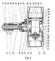
- FIG. 1 Another embodiment that is particularly suitable for large Sizes, differs essentially from the previously described embodiment in that Instead of a hinged anchor, a lifting anchor magnet or motor or piston drive occurs. In this case, too Advantageously separate the drive unit from the fluid part without in to intervene in the fluid circuit. The force of the magnet, the engine or the piston drive is preferred over a toothed segment onto a rack on the sealing tube transfer.
- the linear valve 1 shown in Figure 1 consists of a Fluid housing 2, which in a pipe 3 between two Line sections 4, 5 is fitted, and a drive housing 6, the one-sided with a drive unit 7 after is attached to the top of the fluid housing 2.
- a coil 8 which encloses a hinged anchor 9, who, as long as no counterforce is exerted, by the force of two springs 10, 11 held in position until the circuit of the coil 8 is closed or by means of a manual control device 12 against the Force of the springs 10, 11 of the hinged anchor 9 from the shown Position is moved.
- an extension lever 14 with a toothed segment 15 at its lower End 16 attached, which in an open space 17 of the Fluid housing 2 protrudes and into a toothed segment 18 Sealing pipe 19 engages.
- Valve seat seal 21 pressed and seals the media flow through the channel 22 between the line sections 4, 5 from.
- Linear valve 1 connects the damping part 26 through the its outside fitted seal 28 against the fluid housing 2 from.
- the linear valve 1 is open, the medium flows around the damping part 26 because of the larger cross section 29 at the end of the fluid housing 2.
- the closing of the linear valve 1 is pressure-balanced very quickly, on the one hand because of the thin-walled design of the sealing tube 19 and the other because on Damping part 26 of the sealing tube 19 a pressure equalization takes place as long as the damping part 26 in the larger Cross section 29 of the fluid housing 2 is located. That displaced Medium flows past the damping part 26 into the line section 5.
- Kicks the damping part 26 in the narrower Cross section 30 of the fluid housing 2 includes the seal 28 the gap 31 from all around hermetically. Only through a small throttle bore 32 in the rectangular cross section 50 the medium can flow out of the closed gap 31, whereby the sealing tube 19 closes damped.
- a drain hole 34 from the fluid housing 2 to the outside.
- Sensor elements 35 connected for feedback.
- a lifting armature magnet is used 36 as drive unit 7.
- the lifting armature 36 is in two parts 38, 39, which are connected by a spring 40.
- a toggle 41 with a link 42 at the lower end 39 of the lifting armature 36 fixed and with a second link 43 on Drive housing 6 adjustable clamped by a screw 45 is.
- Another link 44 of the toggle lever 41 is over a transmission 46 connected to a rack 47 in such a way that by the force-displacement ratio a comparatively great force on the toothed segment 18 on the sealing tube 19 is transmitted.
Landscapes
- Engineering & Computer Science (AREA)
- General Engineering & Computer Science (AREA)
- Mechanical Engineering (AREA)
- Physics & Mathematics (AREA)
- Fluid Mechanics (AREA)
- Mechanically-Actuated Valves (AREA)
- Magnetically Actuated Valves (AREA)
- Lift Valve (AREA)
- Valve Device For Special Equipments (AREA)
Claims (14)
- Valve linéaire à action directe et à équilibre de pression, comportant un boítier de fluide (2), un tube d'étanchéité (19) creux déplaçable, agencé dans ledit boítier de fluide (2), la valve disposant en outre d'un siège de valve (20) et d'un corps de valve (49) avec un joint de siège de valve (21), et d'une unité d'entraínement (7) engageant le tube d'étanchéité (19), caractérisée en ce que l'unité d'entraínement (7) est agencée en tant qu'unité isolée à l'extérieur du flux de fluide à côté du tube d'étanchéité (19) et est accouplée au tube d'étanchéité (19) par des moyens de transmission (15, 18) s'engageant les uns dans les autres de manière détachable, de sorte que l'unité d'entraínement (7) peut être détachée du boítier de fluide (12) sans interrompre le flux de fluide.
- Valve linéaire selon la revendication 1, caractérisée en ce que les moyens de transmission présentent un segment denté (15) qui est formé sur un levier de rallonge (14) de l'unité d'entraínement (7) et qui s'engage dans un segment denté (18) sur le tube d'étanchéité (19), dans un espace intermédiaire (17) ouvert du boítier de fluide (2).
- Valve linéaire selon la revendication 2, caractérisée en ce que le levier de rallonge (14) attaque une armature mobile (9) de l'unité d'entraínement (7).
- Valve linéaire selon la revendication 1, caractérisée en ce qu'un levier à genouillère (41) transmet la force de l'unité d'entraínement (7) à un segment denté (18) sur le tube d'étanchéité (19) via une transmission (46).
- Valve linéaire selon la revendication 4, caractérisée en ce que la force de fermeture transmise au tube d'étanchéité (19) est ajustable au moyen d'une vis (45) à laquelle est fixé un élément (44) du levier à genouillère (41).
- Valve linéaire selon l'une des revendications 1 à 5, caractérisée en ce que pour un groupe de sections nominales de passage, on utilise des unités d'entraínement (7) standardisées.
- Valve linéaire selon l'une des revendications 1 à 6, caractérisée en ce que le joint de siège de valve (21) est monté dans le boítier de fluide (2) et en ce que le tube d'étanchéité (19) porte un siège de valve (20) serré par rapport au joint de valve (21).
- Valve linéaire selon l'une des revendications 1 à 7, caractérisée en ce que le tube d'étanchéité (19) est réalisé à paroi mince et en métal.
- Valve linéaire selon l'une des revendications 1 à 7, caractérisée en ce que le tube d'étanchéité (19) est réalisé à paroi mince et en matière plastique.
- Valve linéaire selon l'une des revendications 1 à 9, caractérisée en ce que le tube d'étanchéité (19) est entouré par deux joints à lèvres (23, 24) qui séparent du boítier de fluide (2) fermé, un espace intermédiaire (17) ouvert vers l'unité d'entraínement (7).
- Valve linéaire selon l'une des revendications 1 à 10, caractérisée en ce que le tube d'étanchéité (19) comporte, à l'extrémité (25) opposée au siège de valve (20), une pièce d'amortissement (26) qui est agencée à la manière d'une bague autour du tube d'étanchéité (19), présente une section transversale rectangulaire (50) et est pourvue d'un orifice d'étranglement (32) ainsi que d'un joint annulaire (28).
- Valve linéaire selon l'une des revendications 1 à 11, caractérisée en ce qu'un orifice de drainage (34) forme un passage vers l'extérieur sur la face inférieure (33) du boítier de fluide (2).
- Valve linéaire selon la revendication 12, caractérisée en ce qu'un module de capteur (35) est raccordé à travers l'orifice de drainage (34).
- Valve linéaire selon l'une des revendications 1 à 13, caractérisée en ce qu'elle peut être commutée depuis un mode de fonctionnement "fermée sans entraínement" à un mode de fonctionnement "ouverte sans entraínement", et inversement, sans intervenir dans le circuit de fluide.
Applications Claiming Priority (2)
| Application Number | Priority Date | Filing Date | Title |
|---|---|---|---|
| DE29706688U DE29706688U1 (de) | 1997-04-14 | 1997-04-14 | Linearventil |
| DE29706688U | 1997-04-14 |
Publications (2)
| Publication Number | Publication Date |
|---|---|
| EP0872675A1 EP0872675A1 (fr) | 1998-10-21 |
| EP0872675B1 true EP0872675B1 (fr) | 2002-12-18 |
Family
ID=8038957
Family Applications (1)
| Application Number | Title | Priority Date | Filing Date |
|---|---|---|---|
| EP98106578A Expired - Lifetime EP0872675B1 (fr) | 1997-04-14 | 1998-04-09 | Clapet à flux direct |
Country Status (5)
| Country | Link |
|---|---|
| US (1) | US6116571A (fr) |
| EP (1) | EP0872675B1 (fr) |
| JP (1) | JP2000514163A (fr) |
| DE (2) | DE29706688U1 (fr) |
| WO (1) | WO1998046916A2 (fr) |
Families Citing this family (27)
| Publication number | Priority date | Publication date | Assignee | Title |
|---|---|---|---|---|
| DE19901257C1 (de) | 1999-01-15 | 2000-10-26 | Daimler Chrysler Ag | Regelventil für Tieftemperatur-Einsatz |
| DE19960330C2 (de) * | 1999-12-15 | 2003-08-21 | Astrium Gmbh | Koaxialventil mit elektrischem Stellantrieb |
| US6695817B1 (en) | 2000-07-11 | 2004-02-24 | Icu Medical, Inc. | Medical valve with positive flow characteristics |
| DE10108492A1 (de) * | 2001-02-22 | 2002-09-05 | Mueller Co Ax Gmbh | Koaxialventil |
| WO2002086361A1 (fr) * | 2001-04-18 | 2002-10-31 | Fisher Controls International Llc | Vanne a manchon actionnee au moyen d'un pivot |
| US7066447B2 (en) * | 2001-04-18 | 2006-06-27 | Fisher Controls International Llc. | Sleeve valve with adjustable flow characteristics |
| DE10227550A1 (de) * | 2002-06-14 | 2003-12-24 | Mueller Co Ax Ag | Coaxialventil |
| JP2004108518A (ja) * | 2002-09-19 | 2004-04-08 | Aisin Seiki Co Ltd | 流体バルブ装置 |
| DE10247097A1 (de) * | 2002-10-09 | 2004-04-22 | müller co-ax ag | Ventil mit Dämpfungsglied |
| US20060161115A1 (en) | 2004-11-05 | 2006-07-20 | Fangrow Thomas F | Soft-grip medical connector |
| AU2007201231A1 (en) * | 2006-03-30 | 2007-10-18 | Scotsman Beverage Systems Limited | Beverage Dispense Valve |
| ATE506985T1 (de) | 2006-10-25 | 2011-05-15 | Icu Medical Inc | Medizinischer verbinder |
| US8454579B2 (en) | 2009-03-25 | 2013-06-04 | Icu Medical, Inc. | Medical connector with automatic valves and volume regulator |
| USD644731S1 (en) | 2010-03-23 | 2011-09-06 | Icu Medical, Inc. | Medical connector |
| RU2449194C2 (ru) * | 2010-05-04 | 2012-04-27 | Общество с ограниченной ответственностью Научно-производственное предприятие "Технопроект" | Клапан электромагнитный |
| US8758306B2 (en) | 2010-05-17 | 2014-06-24 | Icu Medical, Inc. | Medical connectors and methods of use |
| US8522821B2 (en) * | 2010-09-17 | 2013-09-03 | Woodward Hrt, Inc. | Torque motor linearization |
| FR2981133B1 (fr) * | 2011-10-10 | 2013-10-25 | In Lhc | Procede de detection de defaillance d'une servovalve et servovalve faisant application. |
| US20140054477A1 (en) * | 2012-08-27 | 2014-02-27 | Ross Arthur Schade | Axial fluid valves with annular flow control members |
| KR101388861B1 (ko) * | 2012-09-06 | 2014-04-23 | 최상진 | 손잡이 부착형 콘밸브 |
| AU2014364218B2 (en) | 2013-12-11 | 2019-06-06 | Icu Medical, Inc. | Check valve |
| USD793551S1 (en) | 2014-12-03 | 2017-08-01 | Icu Medical, Inc. | Fluid manifold |
| USD786427S1 (en) | 2014-12-03 | 2017-05-09 | Icu Medical, Inc. | Fluid manifold |
| CN106579512A (zh) * | 2017-01-11 | 2017-04-26 | 辽宁工程技术大学 | 农用秸秆膨化装置 |
| US11359735B2 (en) * | 2018-05-14 | 2022-06-14 | Hydromat D.O.O. | Axial valve of the modular concept of construction |
| US20230400102A1 (en) * | 2020-10-29 | 2023-12-14 | Miraial Co., Ltd. | Fluid control device |
| US11713813B2 (en) * | 2022-01-03 | 2023-08-01 | Woodward, Inc. | Inline variable sonic valve |
Family Cites Families (20)
| Publication number | Priority date | Publication date | Assignee | Title |
|---|---|---|---|---|
| DE1068966B (de) * | 1959-11-12 | Kruapsack-Griesheim Aktiengesellschaft, Knapsack bei Köln | Gasdichte Durchschleuseinrichtung für den Durchtritt von staubhaltigen Feststoffen, Gasen oder Dämpfen | |
| DE589994C (de) * | 1933-08-05 | 1933-12-21 | Saeureschutz Ges M B H | Durchgangsventil |
| US2622622A (en) * | 1947-10-10 | 1952-12-23 | Gen Controls Co | Fluid control valve |
| DE896140C (de) * | 1949-03-25 | 1953-11-09 | Artur Metz | Vorrichtung zum Regeln des Durchflusses in Leitungen mittels eines rohrfoermigen axialbeweglichen Schiebers |
| US2675508A (en) * | 1953-01-19 | 1954-04-13 | Gen Controls Co | Electromagnetically controlled operator |
| DE951691C (de) * | 1953-07-24 | 1956-10-31 | Zimmermann & Jansen Gmbh | Absperrschieber mit einem beweglichen Absperrkoerper, der aus einem Rohrstueck besteht |
| US3284044A (en) * | 1964-04-03 | 1966-11-08 | Automatic Switch Co | Valve disc guide for lever-operated solenoid valves |
| DE1247793B (de) * | 1964-04-23 | 1967-08-17 | Nostorag A G | Magnetventil |
| CH424679A (de) * | 1964-09-11 | 1966-11-15 | Escher Wyss Ag | Nadelventil für Freistrahlturbine |
| US3570807A (en) * | 1969-01-14 | 1971-03-16 | Bell Aerospace Corp | Electromechanical control valve |
| US3532121A (en) * | 1969-01-15 | 1970-10-06 | Bell Aerospace Corp | Latching valve |
| NL7113700A (fr) * | 1970-10-13 | 1972-04-17 | ||
| DE2109217A1 (de) * | 1971-02-25 | 1972-08-31 | Paetzel H | Ventil, insbesondere für aggressive oder empfindliche Medien |
| DE2426748C3 (de) * | 1974-06-01 | 1979-10-11 | Buerkert Gmbh, 7118 Ingelfingen | Mehrwegemagnetventil für aggressive Medien |
| DE2724901C2 (de) * | 1977-06-02 | 1983-07-07 | Bürkert GmbH, 7118 Ingelfingen | Magnetventil |
| DE2853719A1 (de) * | 1978-12-13 | 1980-07-03 | Siebeck Metallwerk | Ventil fuer fluessigkeiten mit hoher stroemungsgeschwindigkeit |
| US4416301A (en) * | 1981-06-22 | 1983-11-22 | Grove Valve And Regulator Company | Annular piston valve |
| JPS6018680A (ja) * | 1983-07-08 | 1985-01-30 | Walbro Far East | 倍力機構型直動式電磁弁 |
| IT228445Y1 (it) * | 1992-04-14 | 1998-02-19 | Omal Di Bonomi A & C Sas | Valvola frontale a comando pneumatico |
| CH688833A5 (de) * | 1993-05-19 | 1998-04-15 | Fischer Georg Rohrleitung | Ventil. |
-
1997
- 1997-04-14 DE DE29706688U patent/DE29706688U1/de not_active Expired - Lifetime
-
1998
- 1998-04-09 JP JP10543455A patent/JP2000514163A/ja not_active Ceased
- 1998-04-09 WO PCT/EP1998/002067 patent/WO1998046916A2/fr active Application Filing
- 1998-04-09 EP EP98106578A patent/EP0872675B1/fr not_active Expired - Lifetime
- 1998-04-09 US US09/147,389 patent/US6116571A/en not_active Expired - Fee Related
- 1998-04-09 DE DE59806666T patent/DE59806666D1/de not_active Expired - Lifetime
Also Published As
| Publication number | Publication date |
|---|---|
| WO1998046916A3 (fr) | 1999-01-21 |
| WO1998046916A2 (fr) | 1998-10-22 |
| DE29706688U1 (de) | 1997-07-17 |
| DE59806666D1 (de) | 2003-01-30 |
| JP2000514163A (ja) | 2000-10-24 |
| US6116571A (en) | 2000-09-12 |
| EP0872675A1 (fr) | 1998-10-21 |
Similar Documents
| Publication | Publication Date | Title |
|---|---|---|
| EP0872675B1 (fr) | Clapet à flux direct | |
| DE4308678B4 (de) | Ventil mit einer Verstelleinrichtung für das Ventilglied | |
| DE60117219T2 (de) | Elektromagnetisches Ventil | |
| DE4308679A1 (fr) | ||
| EP3263962A1 (fr) | Soupape | |
| DE19960630B4 (de) | Kunststoffventil | |
| DE2623301A1 (de) | Rohrleitungsschalter | |
| EP0928388B1 (fr) | Clapet de turbine | |
| DE69502536T2 (de) | Elektrisch gesteuertes 3-Wege-Ventil | |
| DE10300772A1 (de) | Fluidbetätigter Aktuator | |
| EP3546809B1 (fr) | Dispositif d'arrêt sous-marin | |
| EP3719295B1 (fr) | Soupape d'ouverture et de fermeture d'une conduite de gaz d'échappement et système d'acheminement des gaz d'échappement | |
| EP0846904A1 (fr) | Soupape à actionnement direct. | |
| DE69715199T2 (de) | Ventilanordnung für Heizsysteme und Wasserheizgeräte und Verfahren zu ihrer Herstellung | |
| DE19606040C2 (de) | Schnellschaltendes Hydraulikventil | |
| DE19934383A1 (de) | Dämpfungseinrichtung und Ventileinsatz für eine solche Dämpfungseinrichtung | |
| DE19605895C2 (de) | Druckkraftkompensierte Drosseleinrichtung | |
| DE102008001647A1 (de) | Steuerventil | |
| EP3969789B1 (fr) | Soupape à siège à membrane | |
| EP1467134A1 (fr) | Soupape double électromagnétique avec bobine commune | |
| DE3606102A1 (de) | Schwenkantrieb | |
| DE9107562U1 (de) | Proportionalventil | |
| DE102018124864B4 (de) | Hochdruck-Sicherheitsventil | |
| AT412169B (de) | Verfahren zum betreiben eines hydraulischen umschaltventils | |
| EP0662575A1 (fr) | Mécanisme de vanne avec guidage forcé |
Legal Events
| Date | Code | Title | Description |
|---|---|---|---|
| PUAI | Public reference made under article 153(3) epc to a published international application that has entered the european phase |
Free format text: ORIGINAL CODE: 0009012 |
|
| AK | Designated contracting states |
Kind code of ref document: A1 Designated state(s): DE FR GB IT |
|
| AX | Request for extension of the european patent |
Free format text: AL;LT;LV;MK;RO;SI |
|
| 17P | Request for examination filed |
Effective date: 19990416 |
|
| AKX | Designation fees paid |
Free format text: DE FR GB IT |
|
| GRAG | Despatch of communication of intention to grant |
Free format text: ORIGINAL CODE: EPIDOS AGRA |
|
| 17Q | First examination report despatched |
Effective date: 20020606 |
|
| GRAH | Despatch of communication of intention to grant a patent |
Free format text: ORIGINAL CODE: EPIDOS IGRA |
|
| GRAG | Despatch of communication of intention to grant |
Free format text: ORIGINAL CODE: EPIDOS AGRA |
|
| GRAH | Despatch of communication of intention to grant a patent |
Free format text: ORIGINAL CODE: EPIDOS IGRA |
|
| GRAA | (expected) grant |
Free format text: ORIGINAL CODE: 0009210 |
|
| AK | Designated contracting states |
Kind code of ref document: B1 Designated state(s): DE FR GB IT |
|
| REG | Reference to a national code |
Ref country code: GB Ref legal event code: FG4D Free format text: NOT ENGLISH |
|
| REF | Corresponds to: |
Ref document number: 59806666 Country of ref document: DE Date of ref document: 20030130 Kind code of ref document: P Ref document number: 59806666 Country of ref document: DE Date of ref document: 20030130 |
|
| GBT | Gb: translation of ep patent filed (gb section 77(6)(a)/1977) |
Effective date: 20030428 |
|
| ET | Fr: translation filed | ||
| PLBE | No opposition filed within time limit |
Free format text: ORIGINAL CODE: 0009261 |
|
| STAA | Information on the status of an ep patent application or granted ep patent |
Free format text: STATUS: NO OPPOSITION FILED WITHIN TIME LIMIT |
|
| 26N | No opposition filed |
Effective date: 20030919 |
|
| PGFP | Annual fee paid to national office [announced via postgrant information from national office to epo] |
Ref country code: FR Payment date: 20080312 Year of fee payment: 11 |
|
| PGFP | Annual fee paid to national office [announced via postgrant information from national office to epo] |
Ref country code: IT Payment date: 20080428 Year of fee payment: 11 |
|
| PGFP | Annual fee paid to national office [announced via postgrant information from national office to epo] |
Ref country code: GB Payment date: 20080409 Year of fee payment: 11 |
|
| GBPC | Gb: european patent ceased through non-payment of renewal fee |
Effective date: 20090409 |
|
| REG | Reference to a national code |
Ref country code: FR Ref legal event code: ST Effective date: 20091231 |
|
| PG25 | Lapsed in a contracting state [announced via postgrant information from national office to epo] |
Ref country code: GB Free format text: LAPSE BECAUSE OF NON-PAYMENT OF DUE FEES Effective date: 20090409 Ref country code: FR Free format text: LAPSE BECAUSE OF NON-PAYMENT OF DUE FEES Effective date: 20091222 |
|
| PG25 | Lapsed in a contracting state [announced via postgrant information from national office to epo] |
Ref country code: IT Free format text: LAPSE BECAUSE OF NON-PAYMENT OF DUE FEES Effective date: 20090409 |
|
| PGFP | Annual fee paid to national office [announced via postgrant information from national office to epo] |
Ref country code: DE Payment date: 20130425 Year of fee payment: 16 |
|
| REG | Reference to a national code |
Ref country code: DE Ref legal event code: R119 Ref document number: 59806666 Country of ref document: DE |
|
| PG25 | Lapsed in a contracting state [announced via postgrant information from national office to epo] |
Ref country code: DE Free format text: LAPSE BECAUSE OF NON-PAYMENT OF DUE FEES Effective date: 20141101 |
|
| REG | Reference to a national code |
Ref country code: DE Ref legal event code: R119 Ref document number: 59806666 Country of ref document: DE Effective date: 20141101 |