EP3719295B1 - Soupape d'ouverture et de fermeture d'une conduite de gaz d'échappement et système d'acheminement des gaz d'échappement - Google Patents
Soupape d'ouverture et de fermeture d'une conduite de gaz d'échappement et système d'acheminement des gaz d'échappement Download PDFInfo
- Publication number
- EP3719295B1 EP3719295B1 EP19465519.7A EP19465519A EP3719295B1 EP 3719295 B1 EP3719295 B1 EP 3719295B1 EP 19465519 A EP19465519 A EP 19465519A EP 3719295 B1 EP3719295 B1 EP 3719295B1
- Authority
- EP
- European Patent Office
- Prior art keywords
- valve
- valve body
- plunger
- tappet
- open position
- Prior art date
- Legal status (The legal status is an assumption and is not a legal conclusion. Google has not performed a legal analysis and makes no representation as to the accuracy of the status listed.)
- Active
Links
- 230000008878 coupling Effects 0.000 claims description 15
- 238000010168 coupling process Methods 0.000 claims description 15
- 238000005859 coupling reaction Methods 0.000 claims description 15
- 239000007789 gas Substances 0.000 description 29
- 230000005540 biological transmission Effects 0.000 description 2
- 238000004519 manufacturing process Methods 0.000 description 2
- RRLHMJHRFMHVNM-BQVXCWBNSA-N [(2s,3r,6r)-6-[5-[5-hydroxy-3-(4-hydroxyphenyl)-4-oxochromen-7-yl]oxypentoxy]-2-methyl-3,6-dihydro-2h-pyran-3-yl] acetate Chemical compound C1=C[C@@H](OC(C)=O)[C@H](C)O[C@H]1OCCCCCOC1=CC(O)=C2C(=O)C(C=3C=CC(O)=CC=3)=COC2=C1 RRLHMJHRFMHVNM-BQVXCWBNSA-N 0.000 description 1
- 238000010276 construction Methods 0.000 description 1
- 230000000694 effects Effects 0.000 description 1
- 230000007246 mechanism Effects 0.000 description 1
Images


Classifications
-
- F—MECHANICAL ENGINEERING; LIGHTING; HEATING; WEAPONS; BLASTING
- F02—COMBUSTION ENGINES; HOT-GAS OR COMBUSTION-PRODUCT ENGINE PLANTS
- F02M—SUPPLYING COMBUSTION ENGINES IN GENERAL WITH COMBUSTIBLE MIXTURES OR CONSTITUENTS THEREOF
- F02M26/00—Engine-pertinent apparatus for adding exhaust gases to combustion-air, main fuel or fuel-air mixture, e.g. by exhaust gas recirculation [EGR] systems
- F02M26/65—Constructional details of EGR valves
- F02M26/66—Lift valves, e.g. poppet valves
- F02M26/69—Lift valves, e.g. poppet valves having two or more valve-closing members
-
- F—MECHANICAL ENGINEERING; LIGHTING; HEATING; WEAPONS; BLASTING
- F02—COMBUSTION ENGINES; HOT-GAS OR COMBUSTION-PRODUCT ENGINE PLANTS
- F02M—SUPPLYING COMBUSTION ENGINES IN GENERAL WITH COMBUSTIBLE MIXTURES OR CONSTITUENTS THEREOF
- F02M26/00—Engine-pertinent apparatus for adding exhaust gases to combustion-air, main fuel or fuel-air mixture, e.g. by exhaust gas recirculation [EGR] systems
- F02M26/65—Constructional details of EGR valves
- F02M26/71—Multi-way valves
-
- F—MECHANICAL ENGINEERING; LIGHTING; HEATING; WEAPONS; BLASTING
- F16—ENGINEERING ELEMENTS AND UNITS; GENERAL MEASURES FOR PRODUCING AND MAINTAINING EFFECTIVE FUNCTIONING OF MACHINES OR INSTALLATIONS; THERMAL INSULATION IN GENERAL
- F16K—VALVES; TAPS; COCKS; ACTUATING-FLOATS; DEVICES FOR VENTING OR AERATING
- F16K11/00—Multiple-way valves, e.g. mixing valves; Pipe fittings incorporating such valves
- F16K11/02—Multiple-way valves, e.g. mixing valves; Pipe fittings incorporating such valves with all movable sealing faces moving as one unit
- F16K11/04—Multiple-way valves, e.g. mixing valves; Pipe fittings incorporating such valves with all movable sealing faces moving as one unit comprising only lift valves
- F16K11/044—Multiple-way valves, e.g. mixing valves; Pipe fittings incorporating such valves with all movable sealing faces moving as one unit comprising only lift valves with movable valve members positioned between valve seats
-
- F—MECHANICAL ENGINEERING; LIGHTING; HEATING; WEAPONS; BLASTING
- F16—ENGINEERING ELEMENTS AND UNITS; GENERAL MEASURES FOR PRODUCING AND MAINTAINING EFFECTIVE FUNCTIONING OF MACHINES OR INSTALLATIONS; THERMAL INSULATION IN GENERAL
- F16K—VALVES; TAPS; COCKS; ACTUATING-FLOATS; DEVICES FOR VENTING OR AERATING
- F16K11/00—Multiple-way valves, e.g. mixing valves; Pipe fittings incorporating such valves
- F16K11/10—Multiple-way valves, e.g. mixing valves; Pipe fittings incorporating such valves with two or more closure members not moving as a unit
- F16K11/14—Multiple-way valves, e.g. mixing valves; Pipe fittings incorporating such valves with two or more closure members not moving as a unit operated by one actuating member, e.g. a handle
- F16K11/18—Multiple-way valves, e.g. mixing valves; Pipe fittings incorporating such valves with two or more closure members not moving as a unit operated by one actuating member, e.g. a handle with separate operating movements for separate closure members
-
- F—MECHANICAL ENGINEERING; LIGHTING; HEATING; WEAPONS; BLASTING
- F16—ENGINEERING ELEMENTS AND UNITS; GENERAL MEASURES FOR PRODUCING AND MAINTAINING EFFECTIVE FUNCTIONING OF MACHINES OR INSTALLATIONS; THERMAL INSULATION IN GENERAL
- F16K—VALVES; TAPS; COCKS; ACTUATING-FLOATS; DEVICES FOR VENTING OR AERATING
- F16K31/00—Actuating devices; Operating means; Releasing devices
- F16K31/02—Actuating devices; Operating means; Releasing devices electric; magnetic
- F16K31/06—Actuating devices; Operating means; Releasing devices electric; magnetic using a magnet, e.g. diaphragm valves, cutting off by means of a liquid
- F16K31/08—Actuating devices; Operating means; Releasing devices electric; magnetic using a magnet, e.g. diaphragm valves, cutting off by means of a liquid using a permanent magnet
- F16K31/086—Actuating devices; Operating means; Releasing devices electric; magnetic using a magnet, e.g. diaphragm valves, cutting off by means of a liquid using a permanent magnet the magnet being movable and actuating a second magnet connected to the closing element
-
- F—MECHANICAL ENGINEERING; LIGHTING; HEATING; WEAPONS; BLASTING
- F02—COMBUSTION ENGINES; HOT-GAS OR COMBUSTION-PRODUCT ENGINE PLANTS
- F02M—SUPPLYING COMBUSTION ENGINES IN GENERAL WITH COMBUSTIBLE MIXTURES OR CONSTITUENTS THEREOF
- F02M26/00—Engine-pertinent apparatus for adding exhaust gases to combustion-air, main fuel or fuel-air mixture, e.g. by exhaust gas recirculation [EGR] systems
- F02M26/52—Systems for actuating EGR valves
- F02M26/53—Systems for actuating EGR valves using electric actuators, e.g. solenoids
-
- F—MECHANICAL ENGINEERING; LIGHTING; HEATING; WEAPONS; BLASTING
- F02—COMBUSTION ENGINES; HOT-GAS OR COMBUSTION-PRODUCT ENGINE PLANTS
- F02M—SUPPLYING COMBUSTION ENGINES IN GENERAL WITH COMBUSTIBLE MIXTURES OR CONSTITUENTS THEREOF
- F02M26/00—Engine-pertinent apparatus for adding exhaust gases to combustion-air, main fuel or fuel-air mixture, e.g. by exhaust gas recirculation [EGR] systems
- F02M26/65—Constructional details of EGR valves
- F02M26/72—Housings
Definitions
- the invention relates to a valve for opening and closing an exhaust pipe and an exhaust gas ducting system.
- Valves for letting an exhaust gas flow through are used, inter alia, in motor vehicles and are known from the prior art.
- the tightness with which the valve closes the line is important for the function of such valves.
- a reliable movement of a valve body, which is intended to reliably open or close an exhaust line, in order to be able to regulate the opening and closing of the valve, and a controlled guidance of an exhaust gas flow into the exhaust line are also required.
- the drive of a tappet and the valve body is typically formed by an electric motor and a gearbox.
- the gearing is used to convert the rotary movement of the electric motor into a translatory movement so that the tappet connected to the gearing can move the valve body linearly and open or close an associated exhaust pipe.
- Valves are off, for example WO 2006125259 A1 , US 4705070 A , US 2003075159 A1 , EP 1275838 A1 and US 6041764 A known.
- a valve for opening and closing an exhaust pipe comprises a housing and a first tappet arranged in the housing, which can be coupled to a drive and is designed to be moved along a longitudinal axis of the first tappet by means of the drive.
- the valve further has a second tappet which is arranged in the housing and is designed at a distance from the first tappet to be moved along a longitudinal axis of the second tappet.
- the valve further comprises a first and a second valve seat, which are arranged in the housing and each have a valve outlet, and a first and a second valve body, the first valve body fixed to the first plunger and the second valve body fixed to the second
- the plunger is connected so that the respective valve body can be actuated by moving the respective plunger between an open position in which the respective valve outlet is released and a closed position, the first and second valve bodies being movable in the opposite direction from the open position to the closed position.
- the valve also has a first and a second magnetic element, the first magnetic element being arranged on the first valve body and the second magnetic element being arranged on the second valve body, and the magnetic elements at least in sections forming a magnetic coupling between the first and second tappets.
- the valve is designed in such a way that by means of the contact-free coupling of the tappets to one another, three different positions of the valve bodies and thus three different states of the valve can be formed.
- the tappets are coupled to one another without contact, so that in a first state of the valve the first tappet and the first valve body form a closed position and the second tappet and the second valve body form an open position, in a second state of the valve the first tappet and the first valve body as well as the the second tappet and the second valve body form an open position, and in a third state of the valve the first tappet and the first valve body form an open position and drive the second tappet and the second valve body into a closed position.
- the first plunger is designed to be coupled to a drive and to be driven directly by it. If the magnetic elements of the valve bodies face each other with the same pole orientation, a magnetic force causes the second valve body to repel the second valve body in a corresponding direction when the first tappet and the first valve body approach the second tappet with the second valve body from a certain distance conditional. Alternatively, if the magnetic elements are aligned in opposite directions to one another, a magnetic force of attraction can be formed.
- a direct drive of the first plunger therefore forms an indirect drive for the second plunger in cooperation with the contact-free coupling.
- it can be specified from which distance a movement of the first tappet and the first valve body leads to a movement of the second tappet with the second valve body.
- valve described By means of the valve described, a particularly controlled routing of an exhaust gas flow into different exhaust gas lines is possible during operation, so that an exhaust gas flow can usefully be guided and further processed.
- the valve is particularly suitable for linear valves in which the two tappets are moved linearly along one direction, in particular their respective longitudinal axes, so that an advantageous double linear valve can be implemented with which the respective valve outlets can be closed or opened. It is inexpensive to manufacture and, as a modular concept, offers a clear and simple structure.
- the valve can be used in an exhaust gas recirculation system of a motor vehicle in order to open and close exhaust lines of the motor vehicle.
- an exhaust gas recirculation system of a motor vehicle has the valve.
- the tappets are arranged and designed in the housing in such a way that an opening direction of the first valve body essentially corresponds to a closing direction of the second valve body.
- the first and second plungers are thus moved in opposite directions in order to form a respective open position or closed position.
- the tappets and valve bodies are in particular arranged opposite one another, so that the two tappets form a common longitudinal axis.
- the tappets are coupled to one another without contact, so that a movement of the first tappet and the first valve body at least in sections causes a movement of the second tappet and the second valve body.
- the two plungers and their associated valve bodies form mechanically decoupled closing and opening mechanisms of corresponding valve outlets.
- the described contact-free coupling specifies that a movement of the plungers is at least partially coupled to one another, but there is no direct mechanical connection between the plungers.
- Such a contact-free coupling can be designed, for example, as an electrical, hydraulic and / or in particular as a magnetic coupling, which can influence a movement of the respective tappet on the basis of corresponding force effects.
- the respective magnetic element is designed as an annular permanent magnet and is arranged on a surface of the respective valve body which faces the respective other valve body.
- a permanent magnet ring can be attached to the surface of the respective valve body or extend entirely or partially into the valve body and, for example, form a flush surface termination within a recess of the valve body.
- the magnetic elements can also be designed as a plurality of rod-shaped permanent magnets which are arranged as magnetic pins on one of the opposing surfaces of the respective valve body or extend entirely or partially therein.
- the valve comprises a spring element which is coupled to the second tappet and exerts a predetermined spring force on the second tappet.
- the spring element is designed as a spiral spring and is coupled to the second tappet in a pretensioned manner, so that the second valve body is always driven into an open position in the direction of the first valve body due to the spring force acting.
- the spring force or the coupling force can then predominate or an equilibrium of forces can be established between the forces acting on the first tappet and the second tappet.
- a spring force of the spring element acting on the second tappet is designed in a predetermined manner in coordination with the magnetic coupling between the first and second tappets, so that in a third state of the valve a magnetic force of the magnetic coupling exceeds the spring force of the spring element and the first tappet and the first valve body form an open position and drive the second tappet and the second valve body into a closed position.
- a movement of the first and / or the second tappet therefore takes place on the basis of a balance of forces between the spring force, the magnetic force and the drive force acting by a drive which drives the first tappet.
- the first tappet with the first valve body In a first state of the valve, the first tappet with the first valve body is in the closed position.
- the spring force which drives the second tappet with the second valve body into an open position acts on the second tappet with the second valve body and predominates.
- the first tappet is connected to the first valve body by means of a Drive driven and forms an open position.
- the spring force continues to act on the second tappet with the second valve body and possibly also a magnetic repulsive force of the approaching magnet elements of the two valve bodies. If the spring force continues to predominate or a force equilibrium is set between the drive or holding force on the first tappet, spring force and magnetic force, the second tappet with the second valve body also remains in an open position.
- the first tappet with the first valve body is driven further by means of the drive, so that the first valve body forms a completely open position.
- a magnetic force acts on the second tappet with the second valve body, which outweighs the spring force and drives the second tappet with the second valve body into its closed position.
- the first tappet can be actively driven and the second tappet passively by means of a drive in order to open or close a respective valve outlet and to open or close an exhaust gas line connected to it.
- an exhaust gas routing system comprises an embodiment of the for opening and closing an exhaust gas line which is fluidically coupled with a valve inlet to an inlet line of the exhaust gas routing system and with a valve outlet to an outlet line of the exhaust gas routing system.
- the exhaust gas routing system is arranged as a recirculation system and / or for the aftertreatment of exhaust gases in a motor vehicle in order to enable a controlled guidance of an exhaust gas flow. Since the exhaust gas recirculation system comprises an embodiment of the valve, the properties and features of the valve described are, if applicable, also disclosed for the exhaust gas recirculation system, and vice versa.
- FIG. 1 shows a schematic representation of a valve 100 for opening and closing an exhaust pipe in a perspective view.
- the valve 100 has a housing 1 in which an electric motor 2 is arranged. By means of a gear 3, the rotary movement of the electric motor 2 is converted into a linear movement of a first plunger 41, which is mounted in the housing 1.
- the first tappet 41 extends from a gear chamber 6 into a valve chamber 7, the first tappet 41 being mounted at a first point 81.
- the valve 100 further has a second tappet 42 which is movably arranged at a distance from the first tappet 41 within the housing 1.
- the second tappet 42 extends through a housing cover 13 into the valve chamber 7, the second tappet 42 being mounted at a second location 82.
- the valve chamber 7 consists of three sub-chambers 7a, 7b, 7c lying one behind the other, which are separated from one another by a first and a second valve seat 91 and 92.
- a first valve body 101 is fixedly arranged on the first tappet 41 so that when the first tappet 41 moves linearly along a longitudinal axis L of the first tappet 41 it can rest against the first valve seat 91 and seal a corresponding valve outlet 121 or move away from the first valve seat 91 move away and thus release the corresponding valve outlet 121 and a gas can flow from the valve chamber 7 into an exhaust line.
- a second valve body 102 is fixedly arranged on the second tappet 42 so that when the second tappet 41 moves linearly along the longitudinal axis L it can rest against the second valve seat 92 and seal a corresponding valve outlet 121 or move away from the second valve seat 92 and the corresponding valve outlet 121 thus release and a gas from the valve chamber 7 can flow into another exhaust pipe.
- the tappets 41 and 42 are arranged and designed in the housing 1 in such a way that an opening direction of the first valve body 101 essentially corresponds to a closing direction of the second valve body 102.
- the first and second tappets 41 and 42 are not mechanically connected directly and are moved in opposite directions, that is to say in opposite directions, in order to form a respective open position or closed position.
- valve 100 is described according to an exemplary embodiment of the invention, which, during operation, enables an exhaust gas flow to be guided in a particularly controlled manner through the valve 100 to connectable exhaust gas lines.
- the valve 100 described below can, but does not have to have, features of the with the aid of FIG Figure 1 Have described configuration. It should be pointed out that the valve 100 according to the exemplary embodiment can alternatively, at least partially, also have other configurations, without there being any restrictions for the following description of the exemplary embodiment of the invention.
- FIG. 2 shows a schematic sectional illustration of a side view of the valve 100.
- the valve 100 has a valve inlet 122 and two valve outlets 121, one of which is assigned to the first valve body 101 and one to the second valve body 102.
- the first plunger 41 is coupled to a first bushing 141 and is arranged movably along the longitudinal axis L in the housing 1.
- the second plunger 42 is coupled to a second bush 142 and is arranged in the housing 1 so as to be movable along the longitudinal axis L.
- the valve 100 also has a spring element 15 which, in the form of a pretensioned spiral spring, is arranged in a recess in the housing cover 13.
- the spring element 15 surrounds a section of the second plunger 42 which, like the second bush 142, extends into the recess of the housing cover 13.
- the spring element 15 is thus arranged between the housing cover 13 and the second plunger 42 and is securely guided.
- the spring element exerts an essentially constant spring force on the second bush 142 and the second tappet 42 connected to it in the direction of the first tappet 41 in order to establish an open position of the second valve body 102.
- the valve 1 has a first and a second magnetic element 111 and 112, the first magnetic element 111 on the first valve body 101 and the second magnetic element 112 is arranged on the first valve body 102.
- the magnetic elements 111 and 112 are arranged as ring-shaped permanent magnets on a respective surface of the corresponding valve body 101, 102, which face one another.
- the magnetic rings are partially embedded in the associated valve body 101, 102 or partially arranged in a recess of the respective valve body 101, 102, so that they partially extend beyond a surface of the valve body 101, 102.
- the magnetic elements 111 and 112 form a contact-free, magnetic coupling between the two tappets 41, 42, so that at least in sections a movement of the first tappet 41 causes a movement of the second tappet 42.
- the magnetic elements 111, 112 face each other with the same pole alignment, so that when the first and second tappets 41, 42 come close enough, a repulsive magnetic force acts between the valve bodies 101 and 102, which pushes the second valve body 102 and the second tappet 42 against the direction of force the spring force in the direction of the housing cover 13 drives.
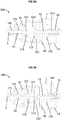
- Figures 3A to 3C each show a schematic sectional illustration of a side view of the valve 100 in three different states.
- Figure 3A shows a first state of the valve 100, in which the first tappet 41 with the first valve body 101 is in the closed position.
- the spring force which drives the second tappet 42 with the second valve body 102 into an open position, acts on the second tappet 42 with the second valve body 102 and predominates.
- Figure 3B shows a second state of the valve 100, which can be formed by driving the first tappet 41 by means of the drive 2.
- the first tappet 41 is driven until the first valve body 101 moves away from the valve seat 91 and releases the valve inlet 121.
- the first tappet 41, the valve body 101 and the first magnetic element 111 attached to it are moved together by means of the linear drive 2 in the direction of the second valve body 102 and form an open position which, however, does not realize a fully open position of the first valve body 101.
- the spring force continues to act on the second plunger 42 with the second valve body 102 and possibly also a magnetic repulsive force of the approaching magnet elements 111, 112 of the two valve bodies 101, 102.
- the second tappet 42 with the second valve body 102 also remains in an open position, so that both Valve bodies 101, 102 release their associated valve outlet openings 121 and enable a corresponding exhaust gas flow.
- the first tappet 41 with the first valve body 101 is driven further by means of the drive 2, so that the first valve body 101 forms a completely open position (see FIG. Figure 3C ).
- a magnetic force acts on the second tappet 42 and the second valve body 102, which outweighs the spring force of the spring element 15 and drives the second tappet 42 with the second valve body 102 into its closed position.
- valve 100 By means of the valve 100 described, a particularly controlled routing of an exhaust gas flow into different exhaust gas lines is possible during operation, so that an exhaust gas flow can usefully be guided and further processed.
- the valve 100 enables indirect actuation of the second tappet 42 and the second valve body 102 and implements a valve structure for opening and closing exhaust lines in a simple and inexpensive manner.
- valve 100 A large number of the described components of the valve 100 can be manufactured from plastic, so that the valve 100 can be manufactured lightly in terms of weight and inexpensively.
- a valve 100 which enables at least three different positions of the tappets 41, 42 and the valve bodies 101, 102, is particularly suitable for linear or double linear valves in an exhaust gas recirculation system. It is inexpensive to manufacture and offers a modular concept with a clear and simple structure.
Landscapes
- Engineering & Computer Science (AREA)
- General Engineering & Computer Science (AREA)
- Mechanical Engineering (AREA)
- Chemical & Material Sciences (AREA)
- Combustion & Propulsion (AREA)
- Magnetically Actuated Valves (AREA)
Claims (7)
- Vanne (100) destinée à ouvrir et fermer une conduite de gaz d'échappement, ladite vanne comprenant :- un boîtier (1),- un premier poussoir (41) qui est disposé dans le boîtier (1), qui peut être accouplé à un entraînement (2) et qui est destiné à être déplacé au moyen de l'entraînement (2) le long d'un axe longitudinal (L) du premier poussoir (41),- un deuxième poussoir (42) qui est disposé dans le boîtier (1) et qui est conçu à distance du premier poussoir (41) pour être déplacé le long d'un axe longitudinal (L) du deuxième poussoir (4),- des premier et deuxième sièges de vanne (91, 92) qui sont disposés dans le boîtier (1) et qui comportent chacun une sortie de vanne (121), et- des premier et deuxième corps de vanne (101, 102), le premier corps de vanne (101) étant relié de manière fixe au premier poussoir (41) et le deuxième corps de vanne (102) étant relié de manière fixe au deuxième poussoir (42) de manière à ce que le corps de vanne respectif (101, 102) puisse être actionné par un mouvement du poussoir respectif (41, 42) entre une position ouverte, dans laquelle la sortie de vanne respective (121) est libérée, et une position fermée, les premier et deuxième corps de vanne (101, 102) pouvant être déplacés dans des sens opposés de la position ouverte à la position fermée,- des premier et deuxième éléments magnétiques (111, 112), le premier élément magnétique (111) étant disposé sur le premier corps de vanne (101) et le deuxième élément magnétique (112) étant disposé sur le deuxième corps de vanne (112) et les éléments magnétiques (111, 112) formant au moins par portions un couplage magnétique entre les premier et deuxième poussoirs (41, 42),les poussoirs (41, 42) étant accouplés l'un à l'autre sans contact de manière à ce que, dans un premier état de la vanne (100), le premier poussoir (41) et le premier corps de vanne (101) forment une position fermée et le deuxième poussoir (42) et le deuxième corps de vanne (102) forment une position ouverte,
et de manière à ce que, dans un troisième état de la vanne (100), le premier poussoir (41) et le premier corps de vanne (101) forment une position ouverte et entraînent le deuxième poussoir (42) et le deuxième corps de vanne (102) dans une position fermée, caractérisée en ce que
dans un deuxième état de la vanne (100), le premier poussoir (41) et le premier corps de vanne (101) ainsi que le deuxième poussoir (42) et le deuxième corps de vanne (102) forment une position ouverte. - Vanne (100) selon la revendication 1, dans laquelle les poussoirs (41, 42) sont accouplés entre eux sans contact et un mouvement du premier poussoir (41) et du premier corps de vanne (101) cause au moins par portions un mouvement du deuxième poussoir (42) et du deuxième corps de vanne (102).
- Vanne (100) selon la revendication 1 ou 2, dans laquelle l'élément magnétique respectif (111, 112) est conçu comme un aimant permanent annulaire et est disposé sur une surface du corps de vanne respectif (101, 102) qui est dirigée vers l'autre corps de vanne respectif (101, 102).
- Vanne (100) selon l'une des revendications 1 à 3, dans laquelle l'élément magnétique respectif (111, 112) est conçu comme une pluralité d'aimants permanents en forme de tige et est disposé sur une surface du corps de vanne respectif (101, 102) qui est dirigée vers l'autre corps de vanne respectif (101, 102).
- Vanne (100) selon l'une des revendications 1 à 4, comprenant :
un élément à ressort (15) qui est accouplé au deuxième poussoir (42) et qui exerce une force de ressort spécifiée sur le deuxième poussoir (42). - Vanne (100) selon l'une des revendications 1 à 5 en liaison avec la revendication 5, dans laquelle une force de ressort de l'élément à ressort (15) agissant sur le deuxième poussoir (42) est conçue en coordination avec l'accouplement magnétique entre le premier et le deuxième poussoir (41, 42) de manière à ce que, dans un troisième état de la vanne (100), une force magnétique de l'accouplement magnétique devienne supérieure à la force de ressort de l'élément à ressort (15) et le premier poussoir (41) et le premier corps de vanne (101) forment une position ouverte et entraînent le deuxième poussoir (42) et le deuxième corps de vanne (102) dans une position fermée.
- Système de guidage de gaz d'échappement, comprenant :- une conduite d'admission et une conduite de sortie destinées à guider un flux de gaz d'échappement, et- un mode de réalisation de la vanne (100) selon l'une des revendications 1 à 6, dans lequel la vanne est accouplée fluidiquement à la conduite d'admission au moyen d'une entrée de vanne (122) et à la conduite de sortie au moyen d'une sortie de vanne (121).
Priority Applications (1)
| Application Number | Priority Date | Filing Date | Title |
|---|---|---|---|
| EP19465519.7A EP3719295B8 (fr) | 2019-04-02 | 2019-04-02 | Soupape d'ouverture et de fermeture d'une conduite de gaz d'échappement et système d'acheminement des gaz d'échappement |
Applications Claiming Priority (1)
| Application Number | Priority Date | Filing Date | Title |
|---|---|---|---|
| EP19465519.7A EP3719295B8 (fr) | 2019-04-02 | 2019-04-02 | Soupape d'ouverture et de fermeture d'une conduite de gaz d'échappement et système d'acheminement des gaz d'échappement |
Publications (3)
| Publication Number | Publication Date |
|---|---|
| EP3719295A1 EP3719295A1 (fr) | 2020-10-07 |
| EP3719295B1 true EP3719295B1 (fr) | 2021-11-24 |
| EP3719295B8 EP3719295B8 (fr) | 2021-12-29 |
Family
ID=66630301
Family Applications (1)
| Application Number | Title | Priority Date | Filing Date |
|---|---|---|---|
| EP19465519.7A Active EP3719295B8 (fr) | 2019-04-02 | 2019-04-02 | Soupape d'ouverture et de fermeture d'une conduite de gaz d'échappement et système d'acheminement des gaz d'échappement |
Country Status (1)
| Country | Link |
|---|---|
| EP (1) | EP3719295B8 (fr) |
Families Citing this family (1)
| Publication number | Priority date | Publication date | Assignee | Title |
|---|---|---|---|---|
| BR102022008473B1 (pt) * | 2022-05-02 | 2023-02-14 | Fernão Falcão | Válvula magnética de acionamento mecânico |
Family Cites Families (5)
| Publication number | Priority date | Publication date | Assignee | Title |
|---|---|---|---|---|
| US4705070A (en) * | 1986-02-04 | 1987-11-10 | Eidsmore Paul G | Isolation on/off valve |
| JPH1113558A (ja) * | 1997-06-23 | 1999-01-19 | Honda Motor Co Ltd | 自動車用エンジンの排気還流制御弁 |
| ATE448399T1 (de) * | 2000-05-03 | 2009-11-15 | Cooper Standard Automotive Inc | Egr-ventileinrichtung |
| ATE484670T1 (de) * | 2001-07-11 | 2010-10-15 | Cooper Standard Automotive D | Abgasrückführungssystem |
| WO2006125259A1 (fr) * | 2005-05-24 | 2006-11-30 | Adelaide Research & Innovation Pty Ltd | Soupape a actionnement magnetique |
-
2019
- 2019-04-02 EP EP19465519.7A patent/EP3719295B8/fr active Active
Also Published As
| Publication number | Publication date |
|---|---|
| EP3719295A1 (fr) | 2020-10-07 |
| EP3719295B8 (fr) | 2021-12-29 |
Similar Documents
| Publication | Publication Date | Title |
|---|---|---|
| DE60223341T2 (de) | Direkt angetriebenes Pneumatikventil mit luftunterstütztem Rückhub | |
| DE102018216874B4 (de) | Pneumatisches Ventil | |
| EP1749146B1 (fr) | Dispositif de reglage d'arbre a cames | |
| EP2004428B1 (fr) | Soupape de commande | |
| EP3591273B1 (fr) | Électrovanne | |
| EP2960123B1 (fr) | Cadre de pliage destiné à allonger le parcours de réglage d'un actionneur pour un composant actionné mécaniquement | |
| EP0872675A1 (fr) | Clapet à flux direct | |
| EP0681128A1 (fr) | Electrovanne | |
| DE102016109865A1 (de) | Elektromagnetische Ventilvorrichtung und System | |
| EP3403008B1 (fr) | Électrovanne et utilisation de celle-ci | |
| EP3719295B1 (fr) | Soupape d'ouverture et de fermeture d'une conduite de gaz d'échappement et système d'acheminement des gaz d'échappement | |
| EP1826034B1 (fr) | Dispositif d'amortissement pneumatique pour véhicule automobile doté de soufflets | |
| EP1939461A2 (fr) | Vanne pneumatique modulaire à tiroir | |
| EP3122951B1 (fr) | Soupape de commande pneumatique pour équipement sanitaire | |
| EP2113698A2 (fr) | Fil dentaire et emballage le contenant | |
| EP2702460B1 (fr) | Vanne pneumatique et son usage pour un consommateur connecté | |
| EP2268949B1 (fr) | Vanne de commutation électrique | |
| EP2966281B1 (fr) | Dispositif de couplage | |
| EP1998092A2 (fr) | Soupape électropneumatique, en particulier soupape pilote d'un distributeur pneumatique | |
| DE102014207393B4 (de) | Ventil | |
| EP2465745A1 (fr) | Dispositif d'actionnement mécanique | |
| EP3403010B1 (fr) | Ensemble vanne électromagnétique, son utilisation et système | |
| EP3446012B1 (fr) | Dispositif pneumatique à plusieurs soupapes et procédé de fabrication | |
| DE102013104642A1 (de) | Elektromagnetische Stellvorrichtung, Verwendung einer solchen elektromagnetischen Stellvorrichtung und System aufweisend eine solche elektromagnetische Stellvorrichtung | |
| EP1477714B1 (fr) | Actionneur pour soupape |
Legal Events
| Date | Code | Title | Description |
|---|---|---|---|
| PUAI | Public reference made under article 153(3) epc to a published international application that has entered the european phase |
Free format text: ORIGINAL CODE: 0009012 |
|
| STAA | Information on the status of an ep patent application or granted ep patent |
Free format text: STATUS: THE APPLICATION HAS BEEN PUBLISHED |
|
| AK | Designated contracting states |
Kind code of ref document: A1 Designated state(s): AL AT BE BG CH CY CZ DE DK EE ES FI FR GB GR HR HU IE IS IT LI LT LU LV MC MK MT NL NO PL PT RO RS SE SI SK SM TR |
|
| AX | Request for extension of the european patent |
Extension state: BA ME |
|
| STAA | Information on the status of an ep patent application or granted ep patent |
Free format text: STATUS: REQUEST FOR EXAMINATION WAS MADE |
|
| 17P | Request for examination filed |
Effective date: 20210407 |
|
| RBV | Designated contracting states (corrected) |
Designated state(s): AL AT BE BG CH CY CZ DE DK EE ES FI FR GB GR HR HU IE IS IT LI LT LU LV MC MK MT NL NO PL PT RO RS SE SI SK SM TR |
|
| GRAP | Despatch of communication of intention to grant a patent |
Free format text: ORIGINAL CODE: EPIDOSNIGR1 |
|
| STAA | Information on the status of an ep patent application or granted ep patent |
Free format text: STATUS: GRANT OF PATENT IS INTENDED |
|
| RIC1 | Information provided on ipc code assigned before grant |
Ipc: F02M 26/66 20160101AFI20210610BHEP Ipc: F02M 26/69 20160101ALI20210610BHEP Ipc: F02M 26/71 20160101ALI20210610BHEP Ipc: F16K 11/18 20060101ALI20210610BHEP Ipc: F16K 11/14 20060101ALI20210610BHEP Ipc: F16K 11/044 20060101ALI20210610BHEP Ipc: F16K 31/08 20060101ALI20210610BHEP |
|
| INTG | Intention to grant announced |
Effective date: 20210705 |
|
| GRAS | Grant fee paid |
Free format text: ORIGINAL CODE: EPIDOSNIGR3 |
|
| GRAA | (expected) grant |
Free format text: ORIGINAL CODE: 0009210 |
|
| STAA | Information on the status of an ep patent application or granted ep patent |
Free format text: STATUS: THE PATENT HAS BEEN GRANTED |
|
| REG | Reference to a national code |
Ref country code: DE Ref legal event code: R081 Ref document number: 502019002843 Country of ref document: DE Owner name: VITESCO TECHNOLOGIES GMBH, DE Free format text: FORMER OWNER: VITESCO TECHNOLOGIES GMBH, 30165 HANNOVER, DE |
|
| AK | Designated contracting states |
Kind code of ref document: B1 Designated state(s): AL AT BE BG CH CY CZ DE DK EE ES FI FR GB GR HR HU IE IS IT LI LT LU LV MC MK MT NL NO PL PT RO RS SE SI SK SM TR |
|
| REG | Reference to a national code |
Ref country code: GB Ref legal event code: FG4D Free format text: NOT ENGLISH |
|
| RAP4 | Party data changed (patent owner data changed or rights of a patent transferred) |
Owner name: VITESCO TECHNOLOGIES GMBH |
|
| REG | Reference to a national code |
Ref country code: DE Ref legal event code: R096 Ref document number: 502019002843 Country of ref document: DE |
|
| REG | Reference to a national code |
Ref country code: AT Ref legal event code: REF Ref document number: 1450048 Country of ref document: AT Kind code of ref document: T Effective date: 20211215 Ref country code: CH Ref legal event code: PK Free format text: BERICHTIGUNG B8 |
|
| REG | Reference to a national code |
Ref country code: IE Ref legal event code: FG4D Free format text: LANGUAGE OF EP DOCUMENT: GERMAN |
|
| REG | Reference to a national code |
Ref country code: LT Ref legal event code: MG9D |
|
| REG | Reference to a national code |
Ref country code: NL Ref legal event code: MP Effective date: 20211124 |
|
| PG25 | Lapsed in a contracting state [announced via postgrant information from national office to epo] |
Ref country code: RS Free format text: LAPSE BECAUSE OF FAILURE TO SUBMIT A TRANSLATION OF THE DESCRIPTION OR TO PAY THE FEE WITHIN THE PRESCRIBED TIME-LIMIT Effective date: 20211124 Ref country code: LT Free format text: LAPSE BECAUSE OF FAILURE TO SUBMIT A TRANSLATION OF THE DESCRIPTION OR TO PAY THE FEE WITHIN THE PRESCRIBED TIME-LIMIT Effective date: 20211124 Ref country code: FI Free format text: LAPSE BECAUSE OF FAILURE TO SUBMIT A TRANSLATION OF THE DESCRIPTION OR TO PAY THE FEE WITHIN THE PRESCRIBED TIME-LIMIT Effective date: 20211124 Ref country code: BG Free format text: LAPSE BECAUSE OF FAILURE TO SUBMIT A TRANSLATION OF THE DESCRIPTION OR TO PAY THE FEE WITHIN THE PRESCRIBED TIME-LIMIT Effective date: 20220224 |
|
| PG25 | Lapsed in a contracting state [announced via postgrant information from national office to epo] |
Ref country code: IS Free format text: LAPSE BECAUSE OF FAILURE TO SUBMIT A TRANSLATION OF THE DESCRIPTION OR TO PAY THE FEE WITHIN THE PRESCRIBED TIME-LIMIT Effective date: 20220324 Ref country code: SE Free format text: LAPSE BECAUSE OF FAILURE TO SUBMIT A TRANSLATION OF THE DESCRIPTION OR TO PAY THE FEE WITHIN THE PRESCRIBED TIME-LIMIT Effective date: 20211124 Ref country code: PT Free format text: LAPSE BECAUSE OF FAILURE TO SUBMIT A TRANSLATION OF THE DESCRIPTION OR TO PAY THE FEE WITHIN THE PRESCRIBED TIME-LIMIT Effective date: 20220324 Ref country code: PL Free format text: LAPSE BECAUSE OF FAILURE TO SUBMIT A TRANSLATION OF THE DESCRIPTION OR TO PAY THE FEE WITHIN THE PRESCRIBED TIME-LIMIT Effective date: 20211124 Ref country code: NO Free format text: LAPSE BECAUSE OF FAILURE TO SUBMIT A TRANSLATION OF THE DESCRIPTION OR TO PAY THE FEE WITHIN THE PRESCRIBED TIME-LIMIT Effective date: 20220224 Ref country code: NL Free format text: LAPSE BECAUSE OF FAILURE TO SUBMIT A TRANSLATION OF THE DESCRIPTION OR TO PAY THE FEE WITHIN THE PRESCRIBED TIME-LIMIT Effective date: 20211124 Ref country code: LV Free format text: LAPSE BECAUSE OF FAILURE TO SUBMIT A TRANSLATION OF THE DESCRIPTION OR TO PAY THE FEE WITHIN THE PRESCRIBED TIME-LIMIT Effective date: 20211124 Ref country code: HR Free format text: LAPSE BECAUSE OF FAILURE TO SUBMIT A TRANSLATION OF THE DESCRIPTION OR TO PAY THE FEE WITHIN THE PRESCRIBED TIME-LIMIT Effective date: 20211124 Ref country code: GR Free format text: LAPSE BECAUSE OF FAILURE TO SUBMIT A TRANSLATION OF THE DESCRIPTION OR TO PAY THE FEE WITHIN THE PRESCRIBED TIME-LIMIT Effective date: 20220225 |
|
| PG25 | Lapsed in a contracting state [announced via postgrant information from national office to epo] |
Ref country code: SM Free format text: LAPSE BECAUSE OF FAILURE TO SUBMIT A TRANSLATION OF THE DESCRIPTION OR TO PAY THE FEE WITHIN THE PRESCRIBED TIME-LIMIT Effective date: 20211124 Ref country code: SK Free format text: LAPSE BECAUSE OF FAILURE TO SUBMIT A TRANSLATION OF THE DESCRIPTION OR TO PAY THE FEE WITHIN THE PRESCRIBED TIME-LIMIT Effective date: 20211124 Ref country code: RO Free format text: LAPSE BECAUSE OF FAILURE TO SUBMIT A TRANSLATION OF THE DESCRIPTION OR TO PAY THE FEE WITHIN THE PRESCRIBED TIME-LIMIT Effective date: 20211124 Ref country code: ES Free format text: LAPSE BECAUSE OF FAILURE TO SUBMIT A TRANSLATION OF THE DESCRIPTION OR TO PAY THE FEE WITHIN THE PRESCRIBED TIME-LIMIT Effective date: 20211124 Ref country code: EE Free format text: LAPSE BECAUSE OF FAILURE TO SUBMIT A TRANSLATION OF THE DESCRIPTION OR TO PAY THE FEE WITHIN THE PRESCRIBED TIME-LIMIT Effective date: 20211124 Ref country code: DK Free format text: LAPSE BECAUSE OF FAILURE TO SUBMIT A TRANSLATION OF THE DESCRIPTION OR TO PAY THE FEE WITHIN THE PRESCRIBED TIME-LIMIT Effective date: 20211124 Ref country code: CZ Free format text: LAPSE BECAUSE OF FAILURE TO SUBMIT A TRANSLATION OF THE DESCRIPTION OR TO PAY THE FEE WITHIN THE PRESCRIBED TIME-LIMIT Effective date: 20211124 |
|
| REG | Reference to a national code |
Ref country code: DE Ref legal event code: R097 Ref document number: 502019002843 Country of ref document: DE |
|
| PLBE | No opposition filed within time limit |
Free format text: ORIGINAL CODE: 0009261 |
|
| STAA | Information on the status of an ep patent application or granted ep patent |
Free format text: STATUS: NO OPPOSITION FILED WITHIN TIME LIMIT |
|
| PG25 | Lapsed in a contracting state [announced via postgrant information from national office to epo] |
Ref country code: AL Free format text: LAPSE BECAUSE OF FAILURE TO SUBMIT A TRANSLATION OF THE DESCRIPTION OR TO PAY THE FEE WITHIN THE PRESCRIBED TIME-LIMIT Effective date: 20211124 |
|
| 26N | No opposition filed |
Effective date: 20220825 |
|
| PG25 | Lapsed in a contracting state [announced via postgrant information from national office to epo] |
Ref country code: SI Free format text: LAPSE BECAUSE OF FAILURE TO SUBMIT A TRANSLATION OF THE DESCRIPTION OR TO PAY THE FEE WITHIN THE PRESCRIBED TIME-LIMIT Effective date: 20211124 |
|
| REG | Reference to a national code |
Ref country code: CH Ref legal event code: PL |
|
| REG | Reference to a national code |
Ref country code: BE Ref legal event code: MM Effective date: 20220430 |
|
| PG25 | Lapsed in a contracting state [announced via postgrant information from national office to epo] |
Ref country code: MC Free format text: LAPSE BECAUSE OF FAILURE TO SUBMIT A TRANSLATION OF THE DESCRIPTION OR TO PAY THE FEE WITHIN THE PRESCRIBED TIME-LIMIT Effective date: 20211124 Ref country code: LU Free format text: LAPSE BECAUSE OF NON-PAYMENT OF DUE FEES Effective date: 20220402 Ref country code: LI Free format text: LAPSE BECAUSE OF NON-PAYMENT OF DUE FEES Effective date: 20220430 Ref country code: CH Free format text: LAPSE BECAUSE OF NON-PAYMENT OF DUE FEES Effective date: 20220430 |
|
| PG25 | Lapsed in a contracting state [announced via postgrant information from national office to epo] |
Ref country code: BE Free format text: LAPSE BECAUSE OF NON-PAYMENT OF DUE FEES Effective date: 20220430 |
|
| PG25 | Lapsed in a contracting state [announced via postgrant information from national office to epo] |
Ref country code: IE Free format text: LAPSE BECAUSE OF NON-PAYMENT OF DUE FEES Effective date: 20220402 |
|
| PG25 | Lapsed in a contracting state [announced via postgrant information from national office to epo] |
Ref country code: IT Free format text: LAPSE BECAUSE OF FAILURE TO SUBMIT A TRANSLATION OF THE DESCRIPTION OR TO PAY THE FEE WITHIN THE PRESCRIBED TIME-LIMIT Effective date: 20211124 |
|
| P01 | Opt-out of the competence of the unified patent court (upc) registered |
Effective date: 20230530 |
|
| GBPC | Gb: european patent ceased through non-payment of renewal fee |
Effective date: 20230402 |
|
| PG25 | Lapsed in a contracting state [announced via postgrant information from national office to epo] |
Ref country code: GB Free format text: LAPSE BECAUSE OF NON-PAYMENT OF DUE FEES Effective date: 20230402 |
|
| PG25 | Lapsed in a contracting state [announced via postgrant information from national office to epo] |
Ref country code: GB Free format text: LAPSE BECAUSE OF NON-PAYMENT OF DUE FEES Effective date: 20230402 |
|
| PG25 | Lapsed in a contracting state [announced via postgrant information from national office to epo] |
Ref country code: MK Free format text: LAPSE BECAUSE OF FAILURE TO SUBMIT A TRANSLATION OF THE DESCRIPTION OR TO PAY THE FEE WITHIN THE PRESCRIBED TIME-LIMIT Effective date: 20211124 Ref country code: CY Free format text: LAPSE BECAUSE OF FAILURE TO SUBMIT A TRANSLATION OF THE DESCRIPTION OR TO PAY THE FEE WITHIN THE PRESCRIBED TIME-LIMIT Effective date: 20211124 |
|
| PG25 | Lapsed in a contracting state [announced via postgrant information from national office to epo] |
Ref country code: HU Free format text: LAPSE BECAUSE OF FAILURE TO SUBMIT A TRANSLATION OF THE DESCRIPTION OR TO PAY THE FEE WITHIN THE PRESCRIBED TIME-LIMIT; INVALID AB INITIO Effective date: 20190402 |
|
| PGFP | Annual fee paid to national office [announced via postgrant information from national office to epo] |
Ref country code: DE Payment date: 20240430 Year of fee payment: 6 |
|
| PGFP | Annual fee paid to national office [announced via postgrant information from national office to epo] |
Ref country code: FR Payment date: 20240425 Year of fee payment: 6 |