EP0870718A1 - Einrichtung zum Festsetzen einer Aufzugskabine - Google Patents
Einrichtung zum Festsetzen einer Aufzugskabine Download PDFInfo
- Publication number
- EP0870718A1 EP0870718A1 EP98105942A EP98105942A EP0870718A1 EP 0870718 A1 EP0870718 A1 EP 0870718A1 EP 98105942 A EP98105942 A EP 98105942A EP 98105942 A EP98105942 A EP 98105942A EP 0870718 A1 EP0870718 A1 EP 0870718A1
- Authority
- EP
- European Patent Office
- Prior art keywords
- elevator car
- screw
- carriageway
- fixing mechanism
- fixing device
- Prior art date
- Legal status (The legal status is an assumption and is not a legal conclusion. Google has not performed a legal analysis and makes no representation as to the accuracy of the status listed.)
- Granted
Links
- 238000004873 anchoring Methods 0.000 title 1
- 230000006835 compression Effects 0.000 claims abstract description 14
- 238000007906 compression Methods 0.000 claims abstract description 14
- 238000012423 maintenance Methods 0.000 description 2
Images



Classifications
-
- B—PERFORMING OPERATIONS; TRANSPORTING
- B66—HOISTING; LIFTING; HAULING
- B66B—ELEVATORS; ESCALATORS OR MOVING WALKWAYS
- B66B7/00—Other common features of elevators
- B66B7/02—Guideways; Guides
- B66B7/022—Guideways; Guides with a special shape
-
- B—PERFORMING OPERATIONS; TRANSPORTING
- B66—HOISTING; LIFTING; HAULING
- B66B—ELEVATORS; ESCALATORS OR MOVING WALKWAYS
- B66B5/00—Applications of checking, fault-correcting, or safety devices in elevators
- B66B5/02—Applications of checking, fault-correcting, or safety devices in elevators responsive to abnormal operating conditions
- B66B5/16—Braking or catch devices operating between cars, cages, or skips and fixed guide elements or surfaces in hoistway or well
- B66B5/18—Braking or catch devices operating between cars, cages, or skips and fixed guide elements or surfaces in hoistway or well and applying frictional retarding forces
-
- B—PERFORMING OPERATIONS; TRANSPORTING
- B66—HOISTING; LIFTING; HAULING
- B66B—ELEVATORS; ESCALATORS OR MOVING WALKWAYS
- B66B7/00—Other common features of elevators
- B66B7/02—Guideways; Guides
- B66B7/04—Riding means, e.g. Shoes, Rollers, between car and guiding means, e.g. rails, ropes
- B66B7/048—Riding means, e.g. Shoes, Rollers, between car and guiding means, e.g. rails, ropes including passive attenuation system for shocks, vibrations
Definitions
- the invention relates to a device for fixing an elevator car that can be moved along a carriageway, the elevator car in releasable connection with the Roadway stands.
- a device is known from application EP 0 081 212 by means of an elevator car which can be moved in a shaft can be fixed.
- the facility is on the Elevator car carrying lower yoke arranged and working with the leg leading the elevator car Guide rail together.
- An electromagnet actuates one Push rod that can be pushed in the direction of the shaft wall their free end when the elevator car descends hits a stop arranged on the guide rail foot, which causes the push rod to move upward relative experiences.
- With the relative movement of the push rod opposite the elevator car becomes a linkage for the actuation of the each arranged on one side of the elevator car Safety gear deflected, with a role of Safety gear is moved on an inclined path until the Roll between the web and the leg of the Guide rail wedged.
- a disadvantage of the known device is that the place where the elevator car can be fixed, is specified by the location of the attack. Another The disadvantage is that between the train and Guide rail wedged roller after fixing the It is difficult to clear the elevator car.
- the invention seeks to remedy this.
- the invention as characterized in claim 1, solves the problem to avoid the disadvantages of the known device and to create a facility by means of which the elevator car anywhere in the elevator shaft with a small one Effort is easy to fix and solve.
- the advantages achieved by the invention are in essential to see that in assembly and / or Maintenance work a safe, detachable connection of the Elevator car with the guide elements is feasible, whereby the fixing device in the grooves of the management bodies intervenes and is forced into its rest position when released is returned. It is also advantageous that operational tensioning devices of the elevator drive can only be released after the elevator car has been fixed can. It is also advantageous that to solve the fixed elevator car the elevator car does not must be raised.
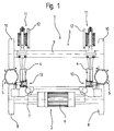
- 1 is an elevator car load-bearing trolley, which consists essentially of a drive unit 2, a support unit 3 and each Side of a lower yoke 4 connecting the units 2, 3 consists.
- the carriage 1 is along one side arranged, for example, vertical lane 5 movable.
- the drive unit 2 consists of a motor 6, a drive axle 7 and each side from a drive wheel 8, that rolls on lane 5.
- the support unit 3 exists from a support axis 9 with a support wheel 10 and each side from a clamping device 11 by means of the frictional force of the Driving wheel 8 and support wheel 10 on roadway 5 can be generated.
- the working area of the jig 11 can be read on a display 12.
- each side Device for fixing the elevator car further Called fixing device 13, arranged on the lower yoke 4.
- the fixing device serving as a clamping element 13 can the elevator car during assembly and / or Maintenance work at any point on the route be releasably connected to the carriageway 5.
- Fig. 1a shows a side view of the trolley 1.
- Die Driving axis 7 of the drive unit 2 is on each side of one Support 14 rotatably connected to the lower yoke 4.
- At the upper end of the vertical yoke 15 an upper yoke, not shown, is arranged.
- Unterjoch 4, drive axis 7, vertical yoke 15 and upper yoke form the Support frame for the elevator car.
- the support axis 9 of the Support unit 3 is rotatable from one side to the other Unterjoch 4 connected rocker 16 worn and depending on the Side on the support axis 9 acting clamping device 11 biased towards lane 5.
- a first tension rod 17 the tensioning device 11 is at one end with the lower yoke connected, at the other end is the first tension rod 17 in Connection to a second tension rod 47.
- the compression spring 18 presses the driving wheel 8 and the support wheel 10 to one each Tread 19 of the road 5 and thus generates the to Movement of the elevator car necessary friction.
- an opening 20 is provided, in which the Fixing device 13 can be used.
- the hollow body trained lane 5 a brake leg 21 for a Carriage 1 arranged not shown brake and each Edge of the tread 19 on an anchor groove 22 which the Connection with the fixing device 13 is used.
- guides 23 for guiding one Counterweight not shown provided in the Cavities of the carriageway 5 .
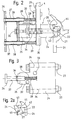
- the fixing device 13 consists of a body 24 with an extension 25, one on Extension 25 arranged handle 26 and made of sliding blocks 27.
- the fixing device 13 is in the opening 20 of the Unterjochs 4 used and on a tab 28 one Carrier plate 29 by means of a first screw 30 fixed.
- the carrier plate 29 has the same opening 20 on like the lower yoke 4 and is by means of a second Screw 31 fastened to the lower yoke 4.
- One on the body 24 The first bore 32 arranged serves the first screw 30 for fastening the fixing device 13 to the lower yoke 4.
- a second bore 33 arranged on the body 24 serves the attachment of the fixing device 13 to the Support axis 9.
- One slot nut 27 sits at the end of one third screw 34 which penetrates the body 24.
- a second compression spring 35 arranged coaxially in the body 24 presses when releasing the connection with the road 5 third screw 34 from the body 24 and lifts the sliding block 27 from the anchor groove 22.
- the handle 26 is by means of a fourth screw 36 on the end face of the extension 25 moored and has the extension 25 projecting laterally Sleeves 37 on.
- a bolt 38 performed, which partially protrudes from the sleeve 37.
- a third Compression spring 39 arranged coaxially.
- the tab 28 has a slot-shaped opening into which the screw neck of the first screw 30 during assembly the fixing device 13 inserted and the first Screw 30 is easily tightened. Then the third screw 34 against the spring force of the second Compression spring 35 advanced and rotated. The one in one Recess 40 of the body 24 guided slot nut 27 is with of the third screw 34 until a first nose 41 of the sliding block 27 on a wall 42 of the anchor groove 22 is present, the first nose 41 a second nose 43 of the Anchor groove 22 engages behind. When tightening the third Screw 34 becomes the second nose 43 between the first Nose 41 and the body 24 pinched, causing the Carriage 1 is detachably connected to the carriageway 5.
- Fig. 4 shows details of the clamping device 11 and Support axis 9.
- Threaded sleeve 44 arranged by means of as in Fig. 5th shown the fixing device 13 on the support axis 9 is moored.
- Threaded bolt 45 arranged, which in a threaded sleeve 46th of the second pull rod 47 can be screwed in.
- the second Tension rod 47 is guided in a hollow axis 50 on which the first compression spring 18 is arranged coaxially.
- first compression spring 18 ends on a fixed pressure plate 51.
- the second end of the first compression spring 18 is by a held on the hollow axis 50 displaceable pressure plate 52.
- a bush 53 arranged and secured by means of a split pin 54.
- the Bush 53 is connected to the slidable Pressure plate 52.
- the fixing device 13 is arranged on the support axis 9.
- One inserted into the second bore 33 of the body 24 fifth screw 55 is in the first threaded sleeve 44 Support axis 9 screwed in.
- the on the support axis 9 attached fixing device 13 prevents access to the first mother 48 and the second mother 49. Before the clamping device 11 can be worked, the Fixing device 13 are removed.
Landscapes
- Engineering & Computer Science (AREA)
- Mechanical Engineering (AREA)
- Lift-Guide Devices, And Elevator Ropes And Cables (AREA)
- Cage And Drive Apparatuses For Elevators (AREA)
- Forklifts And Lifting Vehicles (AREA)
- Maintenance And Inspection Apparatuses For Elevators (AREA)
Abstract
Description
- Fig. 1
- einen entlang einer Fahrbahn verfahrbaren Fahrwagen für eine Aufzugskabine,
- Fig. 1a
- eine Seitenansicht des Fahrwagens,
- Fig. 1b
- eine an einem Unterjoch des Fahrwagens angeordnete Festsetzeinrichtung,
- Fig. 2
- Einzelheiten der am Unterjoch angeordneten Festsetzeinrichtung,
- Fig. 2a
- einen Ausschnitt A1 der Fig. 2 mit Einzelheiten der Verbindung zwischen Festsetzeinrichtung und der Fahrbahn für die Aufzugskabine,
- Fig. 3
- einen Aufriss der Festsetzeinrichtung,
- Fig. 4
- ein an einer Stützachse gelagertes Stützrad eines Aufzugsantriebes und
- Fig. 5
- die an der Stützachse angeordnete Festsetzeinrichtung.
Claims (7)
- Einrichtung zum Festsetzen einer entlang einer Fahrbahn verfahrbaren Aufzugskabine, wobei die Aufzugskabine in lösbarer Verbindung mit der Fahrbahn steht,
dadurch gekennzeichnet,
dass die Aufzugskabine mittels einer Festsetzmechanik (24, 26, 27, 34) an einer beliebigen Stelle des Fahrweges mit der Fahrbahn (5) verbindbar ist. - Einrichtung nach Anspruch 1,
dadurch gekennzeichnet,
dass zu der Festsetzmechanik (24, 26, 27, 34) ein mit der Aufzugskabine lösbar mitgeführtes Klemmelement (13) gehört, welches manuell mit der Fahrbahn (5) verbindbar ist. - Einrichtung nach Anspruch 2,
dadurch gekennzeichnet,
dass zur Herstellung der Verbindung zwischen einem die Aufzugskabine tragenden Fahrwagen (1) und der Fahrbahn (5) verschraubbare in an der Fahrbahn (5) angeordnete Ankernuten (22) einsetzbare Nutsteine (27) vorgesehen sind. - Einrichtung nach Anspruch 3,
dadurch gekennzeichnet,
dass die Nutsteine (27) an von einem Körper (24) getragenen Schrauben (34) angeordnet sind, wobei eine koaxial zur Schraube (34) im Körper (24) angeordnete Druckfeder (35) beim Lösen der Schraube (34) die Nutsteine (27) selbsttätig aus den Ankernuten (22) zieht. - Einrichtung nach Anspruch 4,
dadurch gekennzeichnet,
dass am Körper (24) ein Handgriff (26) mit Hülsen (37) angeordnet ist, in denen Bolzen (38) geführt sind, wobei an den Bolzen (38) Druckfedern (39) koaxial angeordnet sind, die den Körper (24) von einer Trägerplatte (29) wegstossen. - Einrichtung nach den Ansprüchen 1 bis 5,
dadurch gekennzeichnet,
dass zum Festsetzen der Aufzugskabine die Festsetzmechanik (24, 26, 27, 34) am die Aufzugskabine tragenden Fahrwagen (1) angeordnet ist. - Einrichtung nach den Ansprüchen 1 bis 5,
dadurch gekennzeichnet,
dass beim Betrieb der Aufzugskabine die Festsetzmechanik (24, 26, 27, 34) am Fahrwagen (1) angeordnet ist, wobei die Festsetzmechanik (24, 26, 27, 34) Arbeiten an einer Spannvorrichtung (11) des Fahrwagenantriebs (2, 3) verhindert.
Applications Claiming Priority (3)
| Application Number | Priority Date | Filing Date | Title |
|---|---|---|---|
| CH84897 | 1997-04-11 | ||
| CH848/97 | 1997-04-11 | ||
| CH84897 | 1997-04-11 |
Publications (2)
| Publication Number | Publication Date |
|---|---|
| EP0870718A1 true EP0870718A1 (de) | 1998-10-14 |
| EP0870718B1 EP0870718B1 (de) | 2003-06-25 |
Family
ID=4196624
Family Applications (1)
| Application Number | Title | Priority Date | Filing Date |
|---|---|---|---|
| EP98105942A Expired - Lifetime EP0870718B1 (de) | 1997-04-11 | 1998-04-01 | Einrichtung zum Festsetzen einer Aufzugskabine |
Country Status (6)
| Country | Link |
|---|---|
| US (1) | US6032763A (de) |
| EP (1) | EP0870718B1 (de) |
| JP (1) | JPH10279221A (de) |
| AT (1) | ATE243650T1 (de) |
| CA (1) | CA2234543A1 (de) |
| DE (1) | DE59808783D1 (de) |
Cited By (5)
| Publication number | Priority date | Publication date | Assignee | Title |
|---|---|---|---|---|
| EP1860051A1 (de) * | 2006-05-24 | 2007-11-28 | Inventio Ag | Aufzug mit Reibungsantrieb |
| CN101077751B (zh) * | 2006-05-24 | 2010-09-22 | 因温特奥股份公司 | 具有摩擦驱动器的电梯 |
| CN104925616A (zh) * | 2015-05-20 | 2015-09-23 | 杨伦 | 一种避免发生剪切事故电梯 |
| US11912539B2 (en) | 2019-12-18 | 2024-02-27 | Inventio Ag | Method for erecting an elevator installation |
| US12503340B2 (en) * | 2021-03-08 | 2025-12-23 | Mitsubishi Electric Corporation | Carrier device |
Families Citing this family (7)
| Publication number | Priority date | Publication date | Assignee | Title |
|---|---|---|---|---|
| SE530278C2 (sv) * | 2005-10-21 | 2008-04-15 | Alimak Ab | Säkringsanordning för en i en hiss ingående hissvagn |
| WO2008080847A1 (de) * | 2007-01-05 | 2008-07-10 | Continental Teves Ag & Co. Ohg | Aufzugsanlage mit einer aufzugskabine mit einer im bereiche der aufzugskabine angeordneten bremseinrichtung zum halten und bremsen der aufzugkabine und ein verfahren zum halten und bremsen einer solchen aufzugskabine |
| US8517150B2 (en) * | 2007-01-05 | 2013-08-27 | Inventio Ag | Apparatus and method for holding and braking an elevator car |
| CN104495261B (zh) * | 2014-12-10 | 2016-11-30 | 嘉善天慧光电科技有限公司 | 饲料送料平台 |
| JP6854974B2 (ja) * | 2018-05-14 | 2021-04-07 | 三菱電機株式会社 | エレベーターの安全装置、及びエレベーターの安全システム |
| CN110526076A (zh) * | 2019-09-26 | 2019-12-03 | 西继迅达(许昌)电梯有限公司 | 一种复式楼电梯导靴 |
| CN113203009B (zh) * | 2021-05-10 | 2022-11-18 | 马伟元 | 一种医疗检测设备辅助移动装置 |
Citations (3)
| Publication number | Priority date | Publication date | Assignee | Title |
|---|---|---|---|---|
| GB191101621A (en) * | 1911-01-21 | 1911-08-17 | Charles Harry Sivel | Improved Safety Apparatus for Mining Cages, Lifts, and the like. |
| GB1023227A (en) * | 1962-05-15 | 1966-03-23 | Mufulira Copper Mines Ltd | A device for locking a conveyance in a shaft |
| US5497855A (en) * | 1994-09-15 | 1996-03-12 | Moore; Chester G. | Exterior fire fighting and evacuation system for high rise buildings |
Family Cites Families (6)
| Publication number | Priority date | Publication date | Assignee | Title |
|---|---|---|---|---|
| US605820A (en) * | 1898-06-14 | Island | ||
| US483145A (en) * | 1892-09-27 | ailes | ||
| US1124804A (en) * | 1913-12-22 | 1915-01-12 | John Remjas | Elevator safety device. |
| US1129536A (en) * | 1914-05-06 | 1915-02-23 | Andrew Barash | Safety device for elevators. |
| US4113119A (en) * | 1977-02-10 | 1978-09-12 | Si Handling Systems, Inc. | Apparatus for loading articles onto vertically spaced horizontally disposed shelves |
| FR2517658A1 (fr) * | 1981-12-03 | 1983-06-10 | Tabbone Freres Expl Ets | Dispositif de securite pour ascenseur ou monte-charge |
-
1998
- 1998-04-01 EP EP98105942A patent/EP0870718B1/de not_active Expired - Lifetime
- 1998-04-01 DE DE59808783T patent/DE59808783D1/de not_active Expired - Fee Related
- 1998-04-01 AT AT98105942T patent/ATE243650T1/de not_active IP Right Cessation
- 1998-04-06 US US09/055,571 patent/US6032763A/en not_active Expired - Fee Related
- 1998-04-08 CA CA002234543A patent/CA2234543A1/en not_active Abandoned
- 1998-04-10 JP JP10099048A patent/JPH10279221A/ja not_active Ceased
Patent Citations (3)
| Publication number | Priority date | Publication date | Assignee | Title |
|---|---|---|---|---|
| GB191101621A (en) * | 1911-01-21 | 1911-08-17 | Charles Harry Sivel | Improved Safety Apparatus for Mining Cages, Lifts, and the like. |
| GB1023227A (en) * | 1962-05-15 | 1966-03-23 | Mufulira Copper Mines Ltd | A device for locking a conveyance in a shaft |
| US5497855A (en) * | 1994-09-15 | 1996-03-12 | Moore; Chester G. | Exterior fire fighting and evacuation system for high rise buildings |
Cited By (7)
| Publication number | Priority date | Publication date | Assignee | Title |
|---|---|---|---|---|
| EP1860051A1 (de) * | 2006-05-24 | 2007-11-28 | Inventio Ag | Aufzug mit Reibungsantrieb |
| CN101077751B (zh) * | 2006-05-24 | 2010-09-22 | 因温特奥股份公司 | 具有摩擦驱动器的电梯 |
| US8235178B2 (en) | 2006-05-24 | 2012-08-07 | Inventio Ag | Elevator with frictional drive |
| CN104925616A (zh) * | 2015-05-20 | 2015-09-23 | 杨伦 | 一种避免发生剪切事故电梯 |
| CN104925616B (zh) * | 2015-05-20 | 2019-04-12 | 杨伦 | 一种避免发生剪切事故电梯 |
| US11912539B2 (en) | 2019-12-18 | 2024-02-27 | Inventio Ag | Method for erecting an elevator installation |
| US12503340B2 (en) * | 2021-03-08 | 2025-12-23 | Mitsubishi Electric Corporation | Carrier device |
Also Published As
| Publication number | Publication date |
|---|---|
| JPH10279221A (ja) | 1998-10-20 |
| CA2234543A1 (en) | 1998-10-11 |
| ATE243650T1 (de) | 2003-07-15 |
| EP0870718B1 (de) | 2003-06-25 |
| DE59808783D1 (de) | 2003-07-31 |
| US6032763A (en) | 2000-03-07 |
Similar Documents
| Publication | Publication Date | Title |
|---|---|---|
| EP0593803B1 (de) | Vorrichtung zum Positionieren von Lasten | |
| EP0870718B1 (de) | Einrichtung zum Festsetzen einer Aufzugskabine | |
| AT517873B1 (de) | Seilbahnlaufwagen | |
| DE3889483T2 (de) | Autoreparatur- und Richtgestell. | |
| DE2119316A1 (de) | Aufzug für Fahrzeuge | |
| DE1580908C3 (de) | Gehänge für Umlauf-Seilschwebebahnen | |
| DE2533398C3 (de) | Vorrichtung zum Anheben von Kraftfahrzeugen | |
| EP0787676A1 (de) | Sicherheitseinrichtung | |
| AT414332B (de) | Seilbahn und laufwerk | |
| DE69525285T2 (de) | Aufhängevorrichtung eines hydraulischen Aufzugs | |
| DE1755722A1 (de) | Seilschwebebahn | |
| DE3225595A1 (de) | Transportbahn | |
| EP0169349B1 (de) | Befestigungsvorrichtung für die Stufen einer Fahrtreppe | |
| CH657580A5 (de) | Schraegaufzug fuer einen rollstuhl an einem verkehrsmittel. | |
| DE2158162C3 (de) | ||
| DE2914350C2 (de) | Aufzugseinrichtung | |
| WO1999044876A1 (de) | Gleisbremse, insbesondere gefälleausgleichsbremse | |
| DE1913952B2 (de) | Unterflur schleppwagenfoerderanlage | |
| DE20016624U1 (de) | Scherenhubtisch | |
| DE3732837A1 (de) | Hilfsvorrichtung zum abstuetzen von aggregaten von nutzfahrzeugen | |
| DE19540922B4 (de) | Längstransfersystem | |
| DE852680C (de) | Vorrichtung zum Heraufziehen und Herunterlassen von auf Rollen laufenden Behaeltern bei Spezialstrassenfahrzeugen | |
| DE3605508A1 (de) | Bremse fuer einen transportwagen | |
| DE4001601A1 (de) | Kleintransportfahrzeug mit absenkvorrichtung | |
| DE202022103546U1 (de) | Automatisch geschmierte Seilbahnspannvorrichtung |
Legal Events
| Date | Code | Title | Description |
|---|---|---|---|
| PUAI | Public reference made under article 153(3) epc to a published international application that has entered the european phase |
Free format text: ORIGINAL CODE: 0009012 |
|
| AK | Designated contracting states |
Kind code of ref document: A1 Designated state(s): AT CH DE FR GB LI |
|
| AX | Request for extension of the european patent |
Free format text: AL;LT;LV;MK;RO;SI |
|
| 17P | Request for examination filed |
Effective date: 19990317 |
|
| AKX | Designation fees paid |
Free format text: AT CH DE FR GB LI |
|
| 17Q | First examination report despatched |
Effective date: 20011016 |
|
| GRAH | Despatch of communication of intention to grant a patent |
Free format text: ORIGINAL CODE: EPIDOS IGRA |
|
| GRAH | Despatch of communication of intention to grant a patent |
Free format text: ORIGINAL CODE: EPIDOS IGRA |
|
| GRAA | (expected) grant |
Free format text: ORIGINAL CODE: 0009210 |
|
| AK | Designated contracting states |
Designated state(s): AT CH DE FR GB LI |
|
| REG | Reference to a national code |
Ref country code: GB Ref legal event code: FG4D Free format text: NOT ENGLISH |
|
| REG | Reference to a national code |
Ref country code: CH Ref legal event code: EP |
|
| REF | Corresponds to: |
Ref document number: 59808783 Country of ref document: DE Date of ref document: 20030731 Kind code of ref document: P |
|
| GBT | Gb: translation of ep patent filed (gb section 77(6)(a)/1977) | ||
| ET | Fr: translation filed | ||
| PLBE | No opposition filed within time limit |
Free format text: ORIGINAL CODE: 0009261 |
|
| STAA | Information on the status of an ep patent application or granted ep patent |
Free format text: STATUS: NO OPPOSITION FILED WITHIN TIME LIMIT |
|
| 26N | No opposition filed |
Effective date: 20040326 |
|
| PGFP | Annual fee paid to national office [announced via postgrant information from national office to epo] |
Ref country code: AT Payment date: 20070413 Year of fee payment: 10 |
|
| PGFP | Annual fee paid to national office [announced via postgrant information from national office to epo] |
Ref country code: DE Payment date: 20070423 Year of fee payment: 10 |
|
| PGFP | Annual fee paid to national office [announced via postgrant information from national office to epo] |
Ref country code: GB Payment date: 20070426 Year of fee payment: 10 Ref country code: CH Payment date: 20070718 Year of fee payment: 10 |
|
| PGFP | Annual fee paid to national office [announced via postgrant information from national office to epo] |
Ref country code: FR Payment date: 20070416 Year of fee payment: 10 |
|
| REG | Reference to a national code |
Ref country code: CH Ref legal event code: PL |
|
| GBPC | Gb: european patent ceased through non-payment of renewal fee |
Effective date: 20080401 |
|
| PG25 | Lapsed in a contracting state [announced via postgrant information from national office to epo] |
Ref country code: LI Free format text: LAPSE BECAUSE OF NON-PAYMENT OF DUE FEES Effective date: 20080430 Ref country code: DE Free format text: LAPSE BECAUSE OF NON-PAYMENT OF DUE FEES Effective date: 20081101 Ref country code: CH Free format text: LAPSE BECAUSE OF NON-PAYMENT OF DUE FEES Effective date: 20080430 |
|
| REG | Reference to a national code |
Ref country code: FR Ref legal event code: ST Effective date: 20081231 |
|
| PG25 | Lapsed in a contracting state [announced via postgrant information from national office to epo] |
Ref country code: AT Free format text: LAPSE BECAUSE OF NON-PAYMENT OF DUE FEES Effective date: 20080401 |
|
| PG25 | Lapsed in a contracting state [announced via postgrant information from national office to epo] |
Ref country code: FR Free format text: LAPSE BECAUSE OF NON-PAYMENT OF DUE FEES Effective date: 20080430 |
|
| PG25 | Lapsed in a contracting state [announced via postgrant information from national office to epo] |
Ref country code: GB Free format text: LAPSE BECAUSE OF NON-PAYMENT OF DUE FEES Effective date: 20080401 |