EP0867574A2 - Trennwandsystem für Grossraumbüros - Google Patents
Trennwandsystem für Grossraumbüros Download PDFInfo
- Publication number
- EP0867574A2 EP0867574A2 EP98201794A EP98201794A EP0867574A2 EP 0867574 A2 EP0867574 A2 EP 0867574A2 EP 98201794 A EP98201794 A EP 98201794A EP 98201794 A EP98201794 A EP 98201794A EP 0867574 A2 EP0867574 A2 EP 0867574A2
- Authority
- EP
- European Patent Office
- Prior art keywords
- panel
- panels
- frame
- partition
- apertures
- Prior art date
- Legal status (The legal status is an assumption and is not a legal conclusion. Google has not performed a legal analysis and makes no representation as to the accuracy of the status listed.)
- Withdrawn
Links
Images










Classifications
-
- E—FIXED CONSTRUCTIONS
- E04—BUILDING
- E04B—GENERAL BUILDING CONSTRUCTIONS; WALLS, e.g. PARTITIONS; ROOFS; FLOORS; CEILINGS; INSULATION OR OTHER PROTECTION OF BUILDINGS
- E04B2/00—Walls, e.g. partitions, for buildings; Wall construction with regard to insulation; Connections specially adapted to walls
- E04B2/74—Removable non-load-bearing partitions; Partitions with a free upper edge
- E04B2/7407—Removable non-load-bearing partitions; Partitions with a free upper edge assembled using frames with infill panels or coverings only; made-up of panels and a support structure incorporating posts
- E04B2/7416—Removable non-load-bearing partitions; Partitions with a free upper edge assembled using frames with infill panels or coverings only; made-up of panels and a support structure incorporating posts with free upper edge, e.g. for use as office space dividers
- E04B2/7422—Removable non-load-bearing partitions; Partitions with a free upper edge assembled using frames with infill panels or coverings only; made-up of panels and a support structure incorporating posts with free upper edge, e.g. for use as office space dividers with separate framed panels without intermediary support posts
- E04B2/7424—Glazing details
-
- A—HUMAN NECESSITIES
- A47—FURNITURE; DOMESTIC ARTICLES OR APPLIANCES; COFFEE MILLS; SPICE MILLS; SUCTION CLEANERS IN GENERAL
- A47B—TABLES; DESKS; OFFICE FURNITURE; CABINETS; DRAWERS; GENERAL DETAILS OF FURNITURE
- A47B57/00—Cabinets, racks or shelf units, characterised by features for adjusting shelves or partitions
- A47B57/30—Cabinets, racks or shelf units, characterised by features for adjusting shelves or partitions with means for adjusting the height of detachable shelf supports
- A47B57/40—Cabinets, racks or shelf units, characterised by features for adjusting shelves or partitions with means for adjusting the height of detachable shelf supports consisting of hooks coacting with openings
- A47B57/42—Cabinets, racks or shelf units, characterised by features for adjusting shelves or partitions with means for adjusting the height of detachable shelf supports consisting of hooks coacting with openings the shelf supports being cantilever brackets
- A47B57/425—Cabinets, racks or shelf units, characterised by features for adjusting shelves or partitions with means for adjusting the height of detachable shelf supports consisting of hooks coacting with openings the shelf supports being cantilever brackets introduced by a vertical pivoting movement
-
- A—HUMAN NECESSITIES
- A47—FURNITURE; DOMESTIC ARTICLES OR APPLIANCES; COFFEE MILLS; SPICE MILLS; SUCTION CLEANERS IN GENERAL
- A47B—TABLES; DESKS; OFFICE FURNITURE; CABINETS; DRAWERS; GENERAL DETAILS OF FURNITURE
- A47B96/00—Details of cabinets, racks or shelf units not covered by a single one of groups A47B43/00 - A47B95/00; General details of furniture
- A47B96/04—Partition walls
-
- A—HUMAN NECESSITIES
- A47—FURNITURE; DOMESTIC ARTICLES OR APPLIANCES; COFFEE MILLS; SPICE MILLS; SUCTION CLEANERS IN GENERAL
- A47B—TABLES; DESKS; OFFICE FURNITURE; CABINETS; DRAWERS; GENERAL DETAILS OF FURNITURE
- A47B96/00—Details of cabinets, racks or shelf units not covered by a single one of groups A47B43/00 - A47B95/00; General details of furniture
- A47B96/06—Brackets or similar supporting means for cabinets, racks or shelves
-
- E—FIXED CONSTRUCTIONS
- E04—BUILDING
- E04B—GENERAL BUILDING CONSTRUCTIONS; WALLS, e.g. PARTITIONS; ROOFS; FLOORS; CEILINGS; INSULATION OR OTHER PROTECTION OF BUILDINGS
- E04B2/00—Walls, e.g. partitions, for buildings; Wall construction with regard to insulation; Connections specially adapted to walls
- E04B2/74—Removable non-load-bearing partitions; Partitions with a free upper edge
- E04B2/7407—Removable non-load-bearing partitions; Partitions with a free upper edge assembled using frames with infill panels or coverings only; made-up of panels and a support structure incorporating posts
- E04B2/7416—Removable non-load-bearing partitions; Partitions with a free upper edge assembled using frames with infill panels or coverings only; made-up of panels and a support structure incorporating posts with free upper edge, e.g. for use as office space dividers
- E04B2/7422—Removable non-load-bearing partitions; Partitions with a free upper edge assembled using frames with infill panels or coverings only; made-up of panels and a support structure incorporating posts with free upper edge, e.g. for use as office space dividers with separate framed panels without intermediary support posts
- E04B2/7425—Details of connection of panels
-
- E—FIXED CONSTRUCTIONS
- E04—BUILDING
- E04B—GENERAL BUILDING CONSTRUCTIONS; WALLS, e.g. PARTITIONS; ROOFS; FLOORS; CEILINGS; INSULATION OR OTHER PROTECTION OF BUILDINGS
- E04B2/00—Walls, e.g. partitions, for buildings; Wall construction with regard to insulation; Connections specially adapted to walls
- E04B2/74—Removable non-load-bearing partitions; Partitions with a free upper edge
- E04B2/7407—Removable non-load-bearing partitions; Partitions with a free upper edge assembled using frames with infill panels or coverings only; made-up of panels and a support structure incorporating posts
- E04B2/7416—Removable non-load-bearing partitions; Partitions with a free upper edge assembled using frames with infill panels or coverings only; made-up of panels and a support structure incorporating posts with free upper edge, e.g. for use as office space dividers
- E04B2/7433—Removable non-load-bearing partitions; Partitions with a free upper edge assembled using frames with infill panels or coverings only; made-up of panels and a support structure incorporating posts with free upper edge, e.g. for use as office space dividers with panels and support posts
-
- E—FIXED CONSTRUCTIONS
- E04—BUILDING
- E04B—GENERAL BUILDING CONSTRUCTIONS; WALLS, e.g. PARTITIONS; ROOFS; FLOORS; CEILINGS; INSULATION OR OTHER PROTECTION OF BUILDINGS
- E04B2/00—Walls, e.g. partitions, for buildings; Wall construction with regard to insulation; Connections specially adapted to walls
- E04B2/74—Removable non-load-bearing partitions; Partitions with a free upper edge
- E04B2/7407—Removable non-load-bearing partitions; Partitions with a free upper edge assembled using frames with infill panels or coverings only; made-up of panels and a support structure incorporating posts
- E04B2/7448—Removable non-load-bearing partitions; Partitions with a free upper edge assembled using frames with infill panels or coverings only; made-up of panels and a support structure incorporating posts with separate framed panels without intermediary posts, extending from floor to ceiling
-
- E—FIXED CONSTRUCTIONS
- E04—BUILDING
- E04B—GENERAL BUILDING CONSTRUCTIONS; WALLS, e.g. PARTITIONS; ROOFS; FLOORS; CEILINGS; INSULATION OR OTHER PROTECTION OF BUILDINGS
- E04B2/00—Walls, e.g. partitions, for buildings; Wall construction with regard to insulation; Connections specially adapted to walls
- E04B2/74—Removable non-load-bearing partitions; Partitions with a free upper edge
- E04B2/7407—Removable non-load-bearing partitions; Partitions with a free upper edge assembled using frames with infill panels or coverings only; made-up of panels and a support structure incorporating posts
- E04B2/7453—Removable non-load-bearing partitions; Partitions with a free upper edge assembled using frames with infill panels or coverings only; made-up of panels and a support structure incorporating posts with panels and support posts, extending from floor to ceiling
-
- E—FIXED CONSTRUCTIONS
- E04—BUILDING
- E04B—GENERAL BUILDING CONSTRUCTIONS; WALLS, e.g. PARTITIONS; ROOFS; FLOORS; CEILINGS; INSULATION OR OTHER PROTECTION OF BUILDINGS
- E04B2/00—Walls, e.g. partitions, for buildings; Wall construction with regard to insulation; Connections specially adapted to walls
- E04B2/74—Removable non-load-bearing partitions; Partitions with a free upper edge
- E04B2/7407—Removable non-load-bearing partitions; Partitions with a free upper edge assembled using frames with infill panels or coverings only; made-up of panels and a support structure incorporating posts
- E04B2/7453—Removable non-load-bearing partitions; Partitions with a free upper edge assembled using frames with infill panels or coverings only; made-up of panels and a support structure incorporating posts with panels and support posts, extending from floor to ceiling
- E04B2/7455—Glazing details
-
- E—FIXED CONSTRUCTIONS
- E04—BUILDING
- E04F—FINISHING WORK ON BUILDINGS, e.g. STAIRS, FLOORS
- E04F11/00—Stairways, ramps, or like structures; Balustrades; Handrails
-
- E—FIXED CONSTRUCTIONS
- E06—DOORS, WINDOWS, SHUTTERS, OR ROLLER BLINDS IN GENERAL; LADDERS
- E06B—FIXED OR MOVABLE CLOSURES FOR OPENINGS IN BUILDINGS, VEHICLES, FENCES OR LIKE ENCLOSURES IN GENERAL, e.g. DOORS, WINDOWS, BLINDS, GATES
- E06B3/00—Window sashes, door leaves, or like elements for closing wall or like openings; Layout of fixed or moving closures, e.g. windows in wall or like openings; Features of rigidly-mounted outer frames relating to the mounting of wing frames
- E06B3/32—Arrangements of wings characterised by the manner of movement; Arrangements of movable wings in openings; Features of wings or frames relating solely to the manner of movement of the wing
- E06B3/50—Arrangements of wings characterised by the manner of movement; Arrangements of movable wings in openings; Features of wings or frames relating solely to the manner of movement of the wing with more than one kind of movement
- E06B3/5045—Arrangements of wings characterised by the manner of movement; Arrangements of movable wings in openings; Features of wings or frames relating solely to the manner of movement of the wing with more than one kind of movement specially adapted for furniture
-
- E—FIXED CONSTRUCTIONS
- E04—BUILDING
- E04B—GENERAL BUILDING CONSTRUCTIONS; WALLS, e.g. PARTITIONS; ROOFS; FLOORS; CEILINGS; INSULATION OR OTHER PROTECTION OF BUILDINGS
- E04B2/00—Walls, e.g. partitions, for buildings; Wall construction with regard to insulation; Connections specially adapted to walls
- E04B2/74—Removable non-load-bearing partitions; Partitions with a free upper edge
- E04B2002/7461—Details of connection of sheet panels to frame or posts
-
- E—FIXED CONSTRUCTIONS
- E04—BUILDING
- E04B—GENERAL BUILDING CONSTRUCTIONS; WALLS, e.g. PARTITIONS; ROOFS; FLOORS; CEILINGS; INSULATION OR OTHER PROTECTION OF BUILDINGS
- E04B2/00—Walls, e.g. partitions, for buildings; Wall construction with regard to insulation; Connections specially adapted to walls
- E04B2/74—Removable non-load-bearing partitions; Partitions with a free upper edge
- E04B2002/7461—Details of connection of sheet panels to frame or posts
- E04B2002/7462—Details of connection of sheet panels to frame or posts using resilient connectors, e.g. clips
-
- E—FIXED CONSTRUCTIONS
- E04—BUILDING
- E04B—GENERAL BUILDING CONSTRUCTIONS; WALLS, e.g. PARTITIONS; ROOFS; FLOORS; CEILINGS; INSULATION OR OTHER PROTECTION OF BUILDINGS
- E04B2/00—Walls, e.g. partitions, for buildings; Wall construction with regard to insulation; Connections specially adapted to walls
- E04B2/74—Removable non-load-bearing partitions; Partitions with a free upper edge
- E04B2002/7461—Details of connection of sheet panels to frame or posts
- E04B2002/7466—Details of connection of sheet panels to frame or posts using hooks
-
- E—FIXED CONSTRUCTIONS
- E04—BUILDING
- E04B—GENERAL BUILDING CONSTRUCTIONS; WALLS, e.g. PARTITIONS; ROOFS; FLOORS; CEILINGS; INSULATION OR OTHER PROTECTION OF BUILDINGS
- E04B2/00—Walls, e.g. partitions, for buildings; Wall construction with regard to insulation; Connections specially adapted to walls
- E04B2/74—Removable non-load-bearing partitions; Partitions with a free upper edge
- E04B2002/7461—Details of connection of sheet panels to frame or posts
- E04B2002/747—Details of connection of sheet panels to frame or posts using hook and loop-type fasteners
-
- E—FIXED CONSTRUCTIONS
- E04—BUILDING
- E04B—GENERAL BUILDING CONSTRUCTIONS; WALLS, e.g. PARTITIONS; ROOFS; FLOORS; CEILINGS; INSULATION OR OTHER PROTECTION OF BUILDINGS
- E04B2/00—Walls, e.g. partitions, for buildings; Wall construction with regard to insulation; Connections specially adapted to walls
- E04B2/74—Removable non-load-bearing partitions; Partitions with a free upper edge
- E04B2002/7483—Details of furniture, e.g. tables or shelves, associated with the partitions
-
- E—FIXED CONSTRUCTIONS
- E04—BUILDING
- E04B—GENERAL BUILDING CONSTRUCTIONS; WALLS, e.g. PARTITIONS; ROOFS; FLOORS; CEILINGS; INSULATION OR OTHER PROTECTION OF BUILDINGS
- E04B2/00—Walls, e.g. partitions, for buildings; Wall construction with regard to insulation; Connections specially adapted to walls
- E04B2/74—Removable non-load-bearing partitions; Partitions with a free upper edge
- E04B2002/7487—Partitions with slotted profiles
-
- E—FIXED CONSTRUCTIONS
- E04—BUILDING
- E04B—GENERAL BUILDING CONSTRUCTIONS; WALLS, e.g. PARTITIONS; ROOFS; FLOORS; CEILINGS; INSULATION OR OTHER PROTECTION OF BUILDINGS
- E04B2/00—Walls, e.g. partitions, for buildings; Wall construction with regard to insulation; Connections specially adapted to walls
- E04B2/74—Removable non-load-bearing partitions; Partitions with a free upper edge
- E04B2002/749—Partitions with screw-type jacks
-
- Y—GENERAL TAGGING OF NEW TECHNOLOGICAL DEVELOPMENTS; GENERAL TAGGING OF CROSS-SECTIONAL TECHNOLOGIES SPANNING OVER SEVERAL SECTIONS OF THE IPC; TECHNICAL SUBJECTS COVERED BY FORMER USPC CROSS-REFERENCE ART COLLECTIONS [XRACs] AND DIGESTS
- Y10—TECHNICAL SUBJECTS COVERED BY FORMER USPC
- Y10S—TECHNICAL SUBJECTS COVERED BY FORMER USPC CROSS-REFERENCE ART COLLECTIONS [XRACs] AND DIGESTS
- Y10S52/00—Static structures, e.g. buildings
- Y10S52/13—Hook and loop type fastener
-
- Y—GENERAL TAGGING OF NEW TECHNOLOGICAL DEVELOPMENTS; GENERAL TAGGING OF CROSS-SECTIONAL TECHNOLOGIES SPANNING OVER SEVERAL SECTIONS OF THE IPC; TECHNICAL SUBJECTS COVERED BY FORMER USPC CROSS-REFERENCE ART COLLECTIONS [XRACs] AND DIGESTS
- Y10—TECHNICAL SUBJECTS COVERED BY FORMER USPC
- Y10T—TECHNICAL SUBJECTS COVERED BY FORMER US CLASSIFICATION
- Y10T403/00—Joints and connections
- Y10T403/55—Member ends joined by inserted section
- Y10T403/557—Expansible section
-
- Y—GENERAL TAGGING OF NEW TECHNOLOGICAL DEVELOPMENTS; GENERAL TAGGING OF CROSS-SECTIONAL TECHNOLOGIES SPANNING OVER SEVERAL SECTIONS OF THE IPC; TECHNICAL SUBJECTS COVERED BY FORMER USPC CROSS-REFERENCE ART COLLECTIONS [XRACs] AND DIGESTS
- Y10—TECHNICAL SUBJECTS COVERED BY FORMER USPC
- Y10T—TECHNICAL SUBJECTS COVERED BY FORMER US CLASSIFICATION
- Y10T403/00—Joints and connections
- Y10T403/59—Manually releaseable latch type
- Y10T403/591—Manually releaseable latch type having operating mechanism
Definitions
- the present invention relates to partition arrangements for open office spaces and the like, and in particular to a freestanding portable panel and related partition system.
- partition panels are capable of carrying wires in some fashion, so as to provide electrical power at the various work stations for computers, typewriters, dictating equipment, task lighting, and other electrical appliances. These partition panels are also typically capable of routing cabling for telephones, computers, signaling, etc. to the individual work stations. Examples of such panel wiring systems are disclosed in U.S. Patent Nos. 4,429,934; 4,060,294; 4,228,834; and 4,382,648. Wireways and/or raceways are normally provided within the interiors of the panels to carry the utilities throughout the panel system.
- Another desired aspect of the present integrated furnishing system is to provide a panel connection system having increased flexibility for interconnecting reconfigurable partition panels in office layouts.
- a panel connection system is desired that allows use of standardized base panels even where the dimensions of the office layouts are not multiples of the base panel width dimension.
- Additional functionality of the connection system is also desired, such as to permit removing a partition panel from the middle of an in-line wall construction without progressive disassembly of in-line connected partition panels in the wall construction from an unconnected end of the wall construction, and such as to permit some wall sections to be constructed with a non-uniform or increased height.
- Each panel includes a skeleton-like frame having two vertical uprights positioned adjacent opposite side edges thereof.
- a foot extends downwardly from the bottom of the frame to abutting support the panel freestanding on a floor surface.
- Two pairs of horizontal stringers are attached to the outer faces of the uprights in a vertically spaced apart relationship to rigidly interconnect the same, and define therebetween two horizontal raceway cavities which open to the opposite side faces of the frame, and extend continuously between the opposite side edges thereof, such that when like panels are interconnected side-by-side, the open ends of adjacent raceway cavities are aligned and communicate.
- Cover panels enclose at least those portions of the frame side faces disposed between the stringers, and are detachably mounted thereon to provide ready access to the raceway cavities and to permit lay-in wiring therealong.
- the stringers are spaced laterally apart by the uprights to define a vertical raceway cavity between the two horizontal raceway cavities.
- Each vertical upright includes a pair of arms extending upwardly from upper ends thereof to define yoke shaped receptacles for receiving drop-in wiring therein.
- a third pair of horizontal stringers may be attached to the upper ends of the arms to extend generally parallel and coplanar with the first and second pairs of stringers.
- the vertical uprights and horizontal stringers may have a substantially identical tubular construction to facilitate fabrication.
- One aspect of the present invention is a wall construction including a first panel having vertical side edges, and further having a space frame with a frame member defining a row of spaced apart first apertures, the first apertures being accessible from a front of the first panel.
- the wall construction further includes an off-module connector including horizontally spaced oppositely facing hooks configured to securely engage a selected pair of the first apertures at a location spaced from the vertical side edges of the first panel, the off-module connector further defining a second aperture, which when the off-module connectors engage with the selected pair of first apertures, is spaced forwardly from the front of the first panel.
- the wall construction still further includes a second panel including a panel connector located along a marginal edge for securely engaging the second aperture to secure the second panel is a generally perpendicular relationship to the first panel.
- FIG. 1 Another aspect of the present invention is a wall construction including a first panel having vertical edges and further having a frame member that extends generally horizontally, the first panel including a first in-line connector operably mounted on the frame member proximate one of the vertical side edges, the first in-line connector including a slidably extendable bracket having a flange defining horizontally spaced apertures, at least one of which is accessible when the bracket is moved to an extended position that is recessed into the first panel when the bracket is moved to a retracted position.
- the wall construction further includes a second panel aligned and coplanar with the first panel, the second panel including a second in-line connector located generally along a marginal edge thereof for securely engaging the at least one aperture of the bracket when in the extended position to secure the second panel to the first panel.
- Still another aspect of the present invention is a wall construction including a lower panel having a top frame member that extends generally horizontally, an upper panel having a bottom frame member that extends generally horizontally, and a connection system for connecting the upper and lower panels in a stacked arrangement.
- the connection system includes one of the top and bottom frame members defining a repeating pattern of apertures, and the other of the top and bottom frame members including at least one stacking connector, the at least one stacking connector including a pair of opposing clamping members for engaging selected apertures in the repeating pattern.
- the principal objects of the present invention are to provide a freestanding portable partition panel and related system that has enhanced utility carrying capabilities and enhanced reconfigurability.
- the partition panel enables developers and businesses to facilitate change and create lower cost environments to support new work processes in even outdated and/or under-utilized buildings.
- the partition system allows user control over environment, so as to create healthier work areas, which reduces stress and absenteeism.
- the partition system also provides improve utility distribution at lower first time cost, as well as greater flexibility in utilities with lower life cycle costs.
- the partition system provides a new range of design options and allows a full range of levels of privacy.
- the partition system is efficient to use, economical to manufacture, capable of a long operating life, and particularly well adapted for the proposed use.
- the reference numeral 1 (Fig. 1), generally designates a freestanding portable partition system that is designed for use in conjunction with open office spaces 2, and other similar environments to form a plurality of work settings or work stations 3.
- Partition system 1 includes a plurality of similar modular panels 4 (Figs. 2 and 3), which are interconnected so as to define the desired work stations 3.
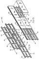
- One such partition panel 4 is illustrated in Figs. 2 and 3, and includes a base panel 5, a stacker panel 6, expressway raceway 7, and a transom 8, which are stacked vertically on top of one another.
- the base panel 5 (Fig. 3) includes a skeleton-like internal frame 9 having at least two vertical uprights 10 positioned adjacent opposite side edge thereof.
- a foot 11 extends downwardly from the bottom of frame 9 to abuttingly support base panel 5 on a floor surface.
- Two pairs of horizontal stringers 12 and 13 are attached to the outer faces of uprights 10 in a vertically spaced apart relationship to rigidly interconnect the same, and define therebetween two horizontal raceway cavities 14 and 15, which open to the opposite side faces of frame 9, and extend continuously between the opposite side edges thereof, such that when like base panels 5 are interconnected side-by-side, the open ends of adjacent raceway cavities 14 and 15 are aligned and communicate.
- Cover panels 16 enclosed at least those portions of the frame side faces disposed between stringers 12 and 13, and are detachably mounted thereon to provide ready access to the raceway cavities 14 and 15, and permit lay-in wiring therealong.
- Each of the illustrated vertical upright 10 (Figs. 9-11) includes a pair of arms 18, which are attached to the outer faces thereof, and extend upwardly from upper ends thereof to define yoke shaped receptacles 19 for receiving drop-in wiring therein.
- a third pair of horizontal stringers 20 are attached to the upper ends of arms 18, and extend generally parallel and coplanar with associated stringers 12 and 13.
- Each pair of stringers 12, 13, and 20 is spaced mutually laterally apart by the associated uprights 10, so as to define a vertical raceway cavity 21 positioned intermediate the two horizontal raceway cavities 14 and 15.
- the illustrated base panel frame 9 (Figs. 9-15) has an open, skeleton-like construction, that is preferably provided in a variety of different widths to accommodate various applications. However, in each illustrated embodiment of base panel 5, the horizontal stringers 12, 13, and 20 are substantially longer than the vertical uprights 10, such that each base panel 5 has a horizontally elongated elevational shape or datum.
- the base panel frame 9 illustrated in Fig. 3 includes a total of five vertical uprights 10, each of which has a substantially identical, square tubular construction, comprising opposite side faces 28 (Figs. 9-15) oriented toward the opposite sides of base panel 5, and opposite end faces 29 oriented toward the opposite end edges of base panel 5.
- the lower ends of vertical uprights 10 are attached to a C-shaped base channel 30, which defines the panel foot 11, and includes a top web 31, and opposite side flanges 32.
- a pair of threaded glides or feet 33 extend through the web 31 of base channel 30 into the bottom ends of outermost uprights 10 to provide vertical adjustability at the opposite sides or ends of base panel 5.
- the illustrated arms 18 have a square tubular construction substantially identical to that of vertical uprights 10, and include opposite side faces 34, as well as opposite end faces 36.
- the lower ends 37 of arms 18 are fixedly attached fixedly to the side faces 28 of vertical uprights 10 adjacent the upper ends thereof, and extend vertically upwardly therefrom a distance of approximately two to four inches in vertical alignment with the associated upright 10, thereby defining the yoke shaped receptacles 19 for drop-in wiring.
- each of the horizontal stringers 12, 13, and 20 has a square tubular construction that is substantially identical with that of vertical uprights 10, and includes opposite faces 40-43, and opposite ends 44.
- Horizontal stringers 12, 13, and 20 have a length substantially identical with that of base panel 30, and are arranged in a mutually parallel, vertically spaced apart relationship.
- stringers 13 are located approximately four inches above floor height, while stringers 12 are located approximately 30 inches above floor height.
- Horizontal stringers 12 and 13 have their inward faces 41 attached to the outer side faces 28 of vertical uprights 10 by means such as welding or the like.
- Stringers 20 have their bottom faces 43 rigidly attached to the upper ends 38 of arms 18, and in one working embodiment of the present invention, the same are positioned approximately 40 inches above floor height.
- Each pair of stringers 12, 13, and 20 is mutually horizontally aligned on opposite sides of its associated vertical uprights 10.
- the stringers 12, 13, and 20 on the opposite sides of vertical uprights 10 are horizontally coplanar, and facilitate the mounting of cover panel 16 and 17 thereon.
- the illustrated horizontal stringers 12, 13, and 20 are slotted to permit like panels 4 to be interconnected and support various accessories thereon, as described in greater detail hereinafter.
- the rear or inward face 41 is full as shown in Fig. 12, while the opposite front face 40 (Fig. 14) includes a series of horizontal slots 50, which extend continuously between opposite ends 44 thereof in a regular pattern.
- the bottom face 42 of horizontal stringers 12 includes an end slot 51 and a series of windows 52, as shown in Fig. 13, while the opposite top face 43 has an end slot 53 and stacker apertures 54, as shown in Fig. 15.
- each clamp bracket 56 is mounted to the opposite ends of each lower stringer 13, and project downwardly therefrom.
- Each clamp bracket 56 includes a semi-circular notch 57 to receive an associated panel-to-panel clamp 58 (Figs. 24b and 29a), as described below.
- the illustrated cover panels 16 and 17 (Figs. 4-8) for base panel 5 have a substantially similar construction, each with a rectangular front elevational shape that includes a top edge 60, bottom edge 61, opposite side edges 62, and opposite faces 63 and 64.
- the front faces 63 of cover panels 16 and 17 are preferably finished, so as to provide and aesthetically pleasing appearance, and may include upholstery, paint, wood veneer, as well as specialty surfaces, such as white board, chalk board, and the like.
- Each cover panel 16 and 17 has a width generally commensurated with that of its associated panel frame 9, and a height generally commensurated with the vertical spacing between an associated pair of horizontal stringers 12, 13, and 20.
- a width generally commensurated with that of its associated panel frame 9
- a height generally commensurated with the vertical spacing between an associated pair of horizontal stringers 12, 13, and 20.
- cover panel 16 extends between medial portions of stringers 12 and 13, while cover panel 17 extends between medial portions of stringers 12 and 20.
- a full height cover 16a is shown in Fig. 4, and extends between medial portions of stringers 13 and 20 to enclose the entire face of base panel frame 9.
- L-shaped brackets 65 are attached to the interior faces 64 of cover panel 16 and 17 adjacent opposite corners thereof by fasteners 66, or another suitable attachment system, such as adhesive, etc.
- Each of the brackets 65 has an outwardly extending flange 67, which receives a spring type mounting clip 68 thereon.
- each clip 68 has a generally S-shaped side elevational configuration, comprising the parallel leg portions 69-71.
- the outer leg 69 and center leg 70 form a U-shaped area that snaps onto the flange 67 of bracket 65, as shown in Figs. 5 and 6.
- the outer leg 71 includes a barb 73 that engages the window 52 on the associated stringers 12, 13, and 20.
- Cover panels 16 and 17 are pushed inwardly onto frames 9, so that clips 68 engage brackets 65 to detachably mount the cover panels (Fig. 8).
- cover panel 16, 17, and 17a are installed on an associated base frame 9 in the following fashion.
- the cover panels 16, 17, and 17a are first selected from a group of different widths and heights to match the panel configuration desired.
- the selected cover panels 16, 17, and 17a are then converged on to the opposite sides of the associated frame 19, with clips 68 engaging the aligned stringers 12, 13, and 20.
- Cover panels 16, 17, and 17a are then urged inwardly against the associated panel frame 9, so that the barb 73 on clips 68 engage aligned windows 52 in horizontal stringers 12, 13, and 20 to securely, yet removably mount the same in place.
- Cover panels 16, 17, and 17a are thereby positioned against or adjacent the outer faces 40 of horizontal stringers 12, 13, and 20, thereby enclosing or completing the horizontal raceway cavities 14 and 15, each of which has a vertically elongated shape when viewed in end elevation.
- the two horizontal raceway cavities 14 dispose between horizontal stringers 12 and 20 are located adjacent work surface height, and define beltway raceway cavities.
- the two horizontal raceway cavities 15 disposed between horizontal stringers 12 and 13 are located adjacent to the panel base, and define lower raceway cavities.
- the illustrated stacker panel 6 (Figs. 3 and 16) has a construction substantially similar to previously described base panel 5, except that it does not have a foot 11 or an intermediate pair of stringers 13.
- Stacker panel 6 also comes in a variety of different widths, as well as various heights, and mounts directly on top of an associated base panel 5, as discussed in greater detail below.
- the stacker panel 6 shown in Fig. 16 has a skeleton-like frame 80, comprising five vertical uprights 81, which are spaced generally regularly along the width of stacker panel 6.
- Each of the vertical uprights 81 is constructed from square tubing, substantially identical to that of base panel uprights 10, and includes opposite pairs of faces 82 and 83.
- Arms 84 (Figs. 17-20), similar to base panel arms 18, are attached to the opposite side faces 82 of each stacker panel upright 81, and extend upwardly from upper ends thereof to define Y-shaped receptacles 85 for drop-in wiring.
- a first pair of horizontal stringers 86 is attached to the upper ends of arms 84, and a second pair of horizontal stringers 87 is attached to the side faces 82 of uprights 81 adjacent the lower ends thereof.
- Both pairs of stringers 86 and 87 are constructed from square tubing substantially similar to vertical uprights 81, as well as the stringers 12, 13, and 20 associated with base panel frame 9.
- Each of the stringers 86 and 87 associated with stacker panel frame 80 has a slotted configuration similar to the stringers 12, 13, and 20 of base panel frame 9, and includes a series of horizontal slots 90 along the forward faces, end slots 91 and windows 92 on the top faces, and end slots 93 on the bottom faces.
- the stacker panel 6 illustrated in Fig. 16 has a height substantially equal to the height of the lower panel 16 of the base panel 5 illustrated in Fig. 3, such that cover panel 16 can be mounted directly on the opposite sides of stacker panel frame 80 in the fashion described above with respect to base panel 5.
- the interior spaces formed between stacker frame uprights 81 and their associated stringers 86 and 87 define horizontal raceway cavities 96 and 97, which open toward the opposite faces of stacker panel 6.
- Horizontal raceway cavities 96 and 97 that are substantially similar to the horizontal raceway cavities 14 and 15 associated with base panel 5, and include open ends, which are aligned and communicate with adjacent like stacker panels to route utilities therebetween.
- Stacker panel 6 also has a vertical raceway cavity 98 (Fig. 17) formed in-between the two horizontal raceway cavities 96 and 97.
- the lower stringers 87 on stacker panel frame 80 include a plurality of vertically extending threaded sleeves 104 positioned regularly along stringers 87, which facilitate mounting stacker panel 6 on an associated base panel 5.
- the lower ends of sleeves 104 extend downwardly from the lower surfaces of stringers 87, and form pilots that are closely received and retained in the apertures 54 in the upper surfaces of stringers 12 on base panel 5.
- Threaded fasteners 105 are inserted upwardly through the apertures 54 in base panel stringers 20, and into the sleeves 104 of stacker panel 6 to securely interconnect the same.
- any given partition panel 4 can be easily varied by selecting the appropriate number and size of base panels 5 and stacker panels 6.
- a single stacker panel 6 is mounted on top of base panel 5 in the following manner. With all cover panel 16, 17, etc. removed, the selected stacker panel frame 80 is placed on top of the associated base panel frame 9, so that the lower stringers 87 of stacker panel frame 80 rest directly on top of the upper stringers 12 on base panel frame 9. The lower ends of sleeves 104 are inserted into apertures 54 on stringers 12 to squarely orient stacker panel frame 80 on top of base panel frame 9.
- Fasteners 105 are then inserted through the apertures 54 in the upper stringer 12 of base panel frame 9, and engaged in sleeves 104 to securely connect stacker panel frame 80 on top of base panel frame 9. Cover panels 16, 17, etc. are then positioned over the outer faces of both frames 9 and 80.
- FIGs. 24a-29a adjacent partition panels 4 are interconnected in an in-line relationship, or side-by-side in the following manner.
- Panel-to-panel clips 110 are provided, each having a plate like construction, with an upturned tab 111 at one end, and a "Z" shaped tab 112 at the opposite end.
- a threaded boss 113 is positioned at a medial portion of the clip 110, and is aligned with a mating aperture in which a threaded fastener 114 is received.
- the associated stringers 12, 13, and 20 are aligned, with the opposite ends abutting one another.
- any stacker panel frames 80 are similarly positioned end-to-end and aligned.
- the panel-to-panel clips 110 are used to interconnect the opposite ends of each adjacent pair of horizontal stringers 12 and 20 in the following manner. As shown in Fig. 27, the "Z" shaped tab 112 of clip 110 is first inserted into the lower window 55 in one of the adjacent stringers, such as the illustrated stringer 12. The head portion 115 of fastener 114 is positioned between the top and bottom faces 42 and 43 of the adjacent stringers 12.
- the upturned tab 111 of clip 110 is then inserted into the lower window 55 of the opposite stringer 12, and fastener 114 is then tightened, which may be accomplished by inserting a tool (not shown) through the windows 51 in the top faces 42 of stringers 12. After all fasteners 114 have been tightened, the opposite tabs 111 and 112 on slips 110 positively interconnect the opposite ends of the associated stringers 12. When a pair of base panels 5 are positioned in-line, preferably the ends of each of stringers 12 and 20 are thusly interconnected, thereby requiring four clips 110.
- a panel-to-panel clamp 58 is used to interconnect the adjacent ends of the lower stringers 13.
- panel-to-panel clamp 58 includes a pair of U-shaped bracket halves 117, each having a pair of apertures 118 through which fasteners 119 are received.
- the two clamp halves 117 are positioned on opposite sides of brackets 56, with fasteners 119 passing through notches 57.
- fasteners 119 are tightened the opposite halves 117 of bracket 58 capture the four adjacent brackets 56 therein to securely interconnect the lower stringers 13 end-to-end.
- partition panels 4 can also be interconnected in a branched or angular configuration in the following fashion.
- Branching clips 120 are provided, and have a generally plate shaped construction, which includes a upturned tab 121 at one end and a horizontally oriented hook 122 at the opposite end.
- a threaded boss 123 is mounted on a lower portion of branching clip 120, and is aligned with a mating aperture in which a threaded fastener 124 is received.
- Branching clip 120 has a L-shaped center portion 125, which extends along the end 44 of an associated one of the stringers, such as the illustrated stringer 12.
- the partition panel 4 can be interconnected to a like partition panel 4 in an angular orientation at locations anywhere along the length of the in-line panels.
- three panels 4 are shown interconnected in an in-line orientation in the fashion described herein above.
- a single panel 4 is shown attached at a 90 degree angle to the three in-line panels at a position intermediate the opposite side edges of the center panel 4.
- the branched panel 4 can be attached anywhere along the length of the three in-line panels, which greatly facilitates space planning.
- a branched panel 4 is mounted in the following manner.
- a pair of branching clips 120 are selected, and hook ends 122 are inserted into the adjacent slots 50 in stringers 12, 13, and 20 at the location at which the branched panel 4 is to be located.
- the heads 126 of fasteners 124 are positioned in the hollow interiors of stringers 12.
- the tab ends 121 of clips 120 are shifted into the lower windows 55 in stringers 12, and fasteners 124 are then tighten to securely interconnect the branched panel 4.
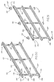
- a wall construction 150 (Fig. 34) includes a plurality of lower/base partition panels 151 and upper/stacking partition panels 152 interconnectable in an infinite number of different in-line, stacked, and off-module arrangements, including combinations thereof. More specifically, the panels 151 and 152 are interconnectable frame to frame with a connection system including mating in-line connectors 153 and 154 (Figs. 39-41), off-module connectors 155 (Figs. 46-48), and stacking connectors 156 (Figs. 52-53).
- the panels 151 and 152 are reconfigurable to meet constantly changing office needs, including the ability to construct walls with "T" intersections located intermediate the vertical side edges of panels, and the ability to construct walls having different heights and/or non-uniform heights. (For example, compare Figs. 34 and 71-75.)
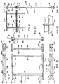
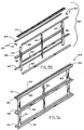
- Base partition panel 151 (Figs. 35-36) includes a base panel space frame 160 having a substantially rectangular side elevational configuration.
- the space frame 160 includes three vertically oriented structural tubes 161, 162 and 163 which are interconnected in a laterally spaced apart relationship by four horizontally oriented structural tubes 164, 165, 166 and 167 and also by a pair of intermediate side frame members 168 and 169.
- the intermediate side frame members 168 and 169 have a C shaped cross section, with the legs of the C shape facing inwardly and engaging the sides of the vertical tubes 161-163 and frame members 168 and 169.
- the tubes 161-167 and side frame members 168 and 169 are welded together to provide a rigid space frame 160 for receiving and interconnecting with other space frames as discussed below.
- the vertical tubes 161-163 extend substantially from the top to the bottom of space frame 155, and the horizontal tubes and side frame members 164-169 extend substantially the width of space frame 160 and align with frame members in adjacently positioned panels.
- top frame member 171 (Fig. 35) is welded to the top of space frame 160.
- Top frame member 171 (Figs. 37-38) has a W shaped cross section, including a U shaped center frame section comprising center flange 172 and vertical side flanges 173 and 174.
- a pair of inverted L shaped side sections extend from side flanges 173 and 174, respectively, including top flanges 175 and 176 and outermost side flanges 177 and 178, respectively.
- the top frame member 171 is welded to top horizontal tubes 164 and 165 (see Fig. 68) to form a rigid matrix.
- a row of apertures 179 (Fig. 35) is welded to the top of space frame 160.
- Top frame member 171 (Figs. 37-38) has a W shaped cross section, including a U shaped center frame section comprising center flange 172 and vertical side flanges 173 and 174.
- the apertures 179 extend partially onto side flanges 177 and 178 so that they are accessible horizontally from a location beside the partition panel through a gap between covers attached to the space frames.
- a pattern 183 of second apertures is also formed at intervals of about every few inches along the top frame member 171, such as every twelve inches.
- Aperture pattern 183 includes a horizontal slot 184 formed in center flange 172, a front-side middle aperture 185 formed at the juncture of flanges 173 and 175, and an opposing rear-side middle aperture 186 is formed at the juncture of flanges 174 and 176.
- Longitudinally adjacent right and left apertures 187 and 188 are formed in flange 173 on both sides of middle aperture 185, and longitudinally adjacent right and left apertures 189 and 190 are formed in flange 174 on both sides of middle apertures 186.
- Pattern 183 further includes notches 191 and 192 formed in selected ones of the apertures 179, the selected ones being the apertures 179' spaced two apertures from the apertures 179'' centered in aperture pattern 183 (Fig. 52).
- the notches 191 and 192 are located in top flanges 175 and 176, respectively, at the corners of the apertures 179' located farthest apart.
- the center flange 172 and side flanges 173 and 174 are cutaway at the opposing ends 172' and 172'' (Fig. 37)of top frame member 171 to provide room for in-line connectors 153 and 154.
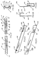
- In-line connector 153 (Fig. 39) includes a W-shaped reinforcement bracket or platform 195 having a center flange 196, vertical intermediate flanges 197 and 198 extending from center flange 196, horizontal flanges 199 and 200 extending from intermediate flanges 197 and 198, and upright vertical side flanges 201 and 202 extending from horizontal flanges 199 and 200.
- Upright flanges 201 and 202 are spaced apart to fit mateably between and against outermost side flanges 177 and 178 at the end of top frame member 171 so that they can be welded to frame member 171.
- a stiffening flange 203 is formed on the outer end of bracket 195 on center flange 196.
- a cinch-plate-receiving aperture 204 is formed at the juncture of center flange 196 and vertical intermediate flange 197 at a location spaced from stiffening flange 203
- a second cinch-plate-receiving aperture 205 is formed at the juncture of center flange 196 and vertical intermediate flange 198 at a second location spaced from stiffening flange 203.
- a U shaped basket 206 is welded to the underside of center flange 196.
- the basket 206 includes spaced apart first and second legs 207 and 208 attached to center flange 196 on opposing longitudinal sides of apertures 204 and 205.
- a cinch plate 210 is located within basket 206.
- Cinch plate 210 includes a body 211 including a threaded hole 211', and opposing wings 212 that extend at an angle outwardly from body 211.
- the wings 212 are spaced apart and configured to extend through the cinch-plate-receiving apertures 204 and 205.
- a screw 214 is configured to extend through a hole 215 in center flange 196 and threadably into cinch plate 210.
- Basket 206 retains cinch plate 210 on bracket 195 and maintains the alignment of the cinch plate 210 with apertures 204 and 205 as screw 214 is turned. By rotating screw 214, cinch plate 210 is drawn against center flange 196, thereby causing wings 213 to extend through apertures 204 and 205.
- Slots 217 and 218 are formed in the ends of horizontal flanges 199 and 200, respectively, for receiving a trim piece, a trim piece retainer or the like.
- In-line connector 154 includes a telescopeably movable bracket 220 (Fig. 40).
- Telescopeable bracket 220 is elongated and U-shaped, and includes a center flange 221 and side flanges 222 and 223 which are configured to mateably rest on and straddle center flange 196 of connector bracket 195 (Fig. 41).
- Two cinch-plate-receiving apertures 224 and 225 are formed along the juncture of flanges 221 and 222, and also two cinch-plate-receiving apertures 226 and 227 are formed along the juncture of flanges 221 and 223.
- a slot 228 extends from an end 229 of bracket 220, and extends past apertures 224-227.
- bracket 220 is configured to mateably slidably rest on center flange 196 of reinforcement bracket 195 of in-line connector 155 in an extended position, with the apertures 225 and 227 aligned with apertures 204 and 205.
- telescopeable bracket 220 is moveable to a retracted position wherein apertures 224 and 226 are aligned with apertures 204 and 205 on reinforcement bracket 195.
- the apertures 224 and 226 are extended to a position alignable with cinch-plate-receiving apertures 204 and 205 on an adjacent and aligned base panel 151 so that the adjacent base panels can be rigidly interconnected in-line and frame-to-frame.
- covers are attached to the sides of base space frame 160. In some situations it may be desirable to support the covers with an intermediate brace 230 (Fig. 42). This also allows the covers to be halved in size, such that one cover can be supported between the top frame member 171 and the intermediate brace 230, and a second cover between the intermediate brace 230 and the intermediate side frame member 168/169.
- the intermediate brace 230 includes a sheet metal bracket 231 welded to vertical structural tubes 161 (and 162 and 163) at a predetermined height. Bracket 231 (Fig.
- the top flange 43 includes an L shaped body having a vertical flange 232 and horizontally disposed top flanges 233, the top flanges 233 defining a notch 233' therebetween for mateably engaging the vertical structural tube 161 (or tubes 162-163).
- the top flanges 233 include holes 234.
- the lower edge of vertical flange 232 includes teeth 235.
- Intermediate brace 230 also includes a structural beam 236 (Fig. 44) that is generally C shaped.
- Brace 236 includes a top flange 237 having holes 237', a vertical flange 238 having a row of apertures 238' and paired holes 239 periodically spaced across its length, and a lower flange 240 defining a space configured to mateably receive teeth 235 on bracket 231.
- Structural beam 236 is attached to bracket 231 by positioning teeth 235 in the space defined by lower flange 240 (Fig. 45), and by tipping beam 236 onto bracket 231 so that holes 237' in brace 236 align with holes 234 in bracket 231.
- Screws 240' are extended through the aligned holes 234 and 237 to secure the beam 236 to base space frame 151.
- the apertures 238' are generally identical to apertures 179 of top frame member 171 in shape and function.
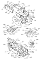
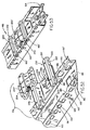
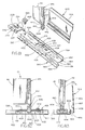
- the off module connector 155 (Fig. 46) includes a pair of configured plates 245 and 246 slidably interconnected by a pair of rivets or headed bolts 247 and 248.
- Lower plate 245 is generally Z shaped and includes an upper flange 249 having hooks 250, a middle flange 251 that extends generally perpendicular to upper flange 249, and a lower flange 252 the extends from middle flange 251 parallel upper flange 249.
- a pair of holes 253 are formed in middle flange 251, along with a window 254 located between the holes 253.
- a pair of apertures 255 and 256 are formed in lower flange 252.
- a slot 257 extends from the free edge 258 of lower flange 252 between apertures 255 and 256.
- An angled tab 259 extends from free edge 258 along a side edge of lower flange 252.
- Upper plate 246 is also generally Z shaped so that it matingly slidingly engages lower plate 245.
- Upper plate 246 includes an upper flange 260 having hooks 261, a middle flange 262 that extends generally perpendicular to upper flange 260, and a lower flange 263 the extends from middle flange 262 parallel upper flange 260.
- Hooks 261 face in a direction opposite to hooks 250.
- a pair of aligned slots 264 are formed in middle flange 262, along with a window 265 located between the holes 264.
- Rivets 247 and 248 extend loosely through holes 253 and slots 264 so that upper plate 246 can slide on lower plate 245 with rivets 247 and 248 sliding within slots 264 on middle flange 262 of upper plate 246.
- a pair of apertures 266 and 267 are formed in lower flange 263.
- a slot 268 extends from the free edge 269 of lower flange 263 between apertures 266 and 267.
- An angled tab 270 extends from free edge 269 along a side edge of lower flange 263.
- Plates 245 and 246 are moveable to a collapsed first position where hooks 250 and 261 are positioned to form a minimum dimension so that the hooks can be slid into selected ones of apertures 179 in top frame member 171.
- the plates 245 and 246 are also moveable to an expanded second position (shown in Fig. 47) where the hooks 250 and 261 are spread apart to securely engage the apertures 179.
- the apertures 255 and 266, and also the apertures 256 and 267 are aligned so that they can be engaged by the wings 212 on cinch plate 210 of an in-line connector 152.
- the angled tabs 259 and 270 are adapted to engage the recesses defined beside the center flange 172 of top frame member 171 to limit the expanding /collapsing movement of plates 245 and 246 and to help center off-module bucket 154 on an off-module connected panel.
- the off-module connector 155 is adapted to be installed and secured selectively along the base space frame 160. Once installed, a base panel 151 can be positioned in an off-module arrangement (see Figs. 48 and 76) so that an in-line connector 153 on the base panel can be attached to the off-module connector 155 with its cinch plate 210 engaging apertures 255, 266, 256, and 267.
- the off-module connector 155 connects the frame of the off-module space frame 160 directly to the base panel frame 160, such that the interconnection is particularly rigid.
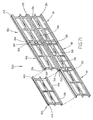
- Stacking panel 152 (Figs. 50-51) includes a space frame 280 substantially structurally identical to base space frame 160 except as noted below.
- the stacking space frame 280 includes a plurality of vertically oriented structural tubes 281, 282, and 283 which are interconnected in a laterally spaced apart relationship by a plurality of horizontally oriented structural tubes 284, 285, 286, and 287 and also by a pair of intermediate side frame members 288 and 289.
- the vertical tubes 281-283 extend substantially from the top to the bottom of space frame 280, and the horizontal tubes and side frame members 284-289 extend substantially the length of space frame 280.
- a top frame member 290 is attached horizontally to the top of stacking space frame 280, the top frame member 290 being similar to base top frame member 171.
- a plurality of upright transom-supporting brackets 291 are optionally attached to the top of stacking panel 290 to support a transom thereon.
- Transom-supporting bracket 291 comprises a lower panel 291' welded or bolted to top frame member 290, and a pair of oppositely facing C-shaped channels 291'' configured to receive and retain elongated transom panels, such as windows or opaque sound absorbing panels not unlike covers 334.
- a plurality of spaced apart stacking connectors 156 are attached to the bottom of stacking panel 152 at spaced apart positions corresponding to the spacing of aperture patterns 183 on top frame member 171 (Figs. 35-37). This allows the stacking partition panel 152 to be selectively positioned on top frame member 171 in any of a variety of different ⁇ longitudinally spaced positions, several of which are staggered. (For example, see Figs. 74 and 76.)
- Stacking connectors 156 each include a carrier bracket 292 and a pair of opposing clamping members or gripping members 294 and 294' slidably mounted on the carrier bracket 292.
- An actuator 293 operably engages the clamping members 294 and 294' to forcibly spread apart the clamping members into interlocking engagement with the selected aperture pattern 183.
- the present invention is contemplated to include other stacking connector designs, such as a stacking connector constructed so that its clamping members are drawn together into engagement with outwardly facing apertures in a top frame member of a space frame.
- the carrier bracket 292 (Fig. 52) is a stamped sheet metal part that includes a center flange 295 and a pair of inverted U shaped locating flanges 296 and 297 extending from the longitudinal sides of center flange 295.
- An aperture 298 is formed in center flange 295, and tabs 299 and 300 extend upwardly from center flange 295 for slidably engaging and aligning clamping members 294 and 294' on carrier bracket 292.
- Locating flanges 296 and 297 each include notches 302 and tabs 303 at their front and rear ends for mateably engaging notches 191 and 192 in apertures 179' of aperture pattern 183.
- bracket center flange 295 is juxtaposed above center flange 172 of top frame member 171, and bracket tabs 303 interlockingly engage the apertures 179' in top frame member 171.
- stacking connector 156 can be selectively engaged with top frame member 171 at any of a plurality of different staggered/interconnected positions. This allows the vertical side edges 304 of stacking partition panel space frame 280 to be offset from the vertical side edges 305 of base partition panel space frame 160, in order to form a stronger stacked arrangement of panels. (See Fig. 74.)
- Clamping members 294 and 294' are substantially mirror images of each other, except as described below.
- Clamping member 294 (Fig. 54) includes a body 307 having an outer surface 308 and an inner surface 309. A pair of lower fingers 310 and 311 extend from the outer surface 308 at the bottom thereof, and a centered upper finger 312 extends from the top of outer surface 308. Fingers 310-312 are configured to matingly engage apertures 187, 189 and 185, respectively, (Fig. 52) on one side of aperture pattern 183 in top frame member 171.
- the bottom surface of clamping member 294 is configured to slidably rest on and engage the center flange 172 of carrier bracket 292.
- An oblong aperture 316 having ends defining a pair of spaced apart hole-like surfaces 317 and 318 extends horizontally through clamping member 294 from front to rear.
- a hole 315 extends horizontally through clamping member 294' and aligns with the hole-like surface 317 in clamping member 294'.
- Actuator 293 includes an elongated nut 320 configured to matingly non-rotatingly engage hole 315.
- the nut 320 includes a washer-like flange 321 on its inner end configured to matingly engage a depression 322 on the inner surface of clamping member 294'.
- Actuator 293 further includes a first shaft 323 configured to threadably engage nut 320 for rotation therein.
- Shaft 323 also includes a portion that extends through the hole-like surface 317 in clamping member 294.
- a second shaft 325 operably engages the second hole-like surface 318 in clamping member 294.
- Intermeshing gears 327 and 328 are formed on the adjacent ends of shafts 323 and 325, respectively.
- Hex-shaped recesses 329 and 330 are formed in the rear end of shaft 323 and on the front end of shaft 325, respectively.
- the hex-shaped recesses 329 and 330 are engageable with an Allan wrench though apertures 193'' (Fig. 52) to actuate actuator 293.
- the Allan wrench when one shaft is rotated by the Allan wrench, the other shaft is simultaneously oppositely rotated by the intermeshing gears 327 and 328. This causes the shaft 323 to gradually rotate out of nut 32O, thus forcing the clamping members 294 and 294' apart. This causes fingers 310-312 to interlocking engage apertures 185-190 of aperture pattern 183.
- Cover retainers 355 are provided for securing covers 334 (Fig. 62) to base and stacking space frames 160 and 280.
- Retainers 355 include threaded shafts 356 for engaging holes 355' in horizontal structural frame members 168-169, 171, and 230 (Figs. 42 and 67).
- Retainers 355 (Figs. 60-61) further include tapered heads 357 and washers 358 defining a recess/groove 359 therebetween.
- Covers 334 are configured for attachment to cover retainers 355.
- Covers 334 include a sound-absorbing composite panel 335 aesthetically covered with upholstery or the like and having a selected size.
- a marginal frame 336 is attached to the edges of panel 335, including a top marginal frame section 337 (Fig. 63) and a bottom marginal frame section 338.
- the top marginal frame member 337 includes an inner flange 339, a top flange 340, and a front flange 341.
- a plurality of attachment apertures 342 and 343 are formed along top marginal frame member 337, apertures 342 being formed in inner flange 339, and apertures 343 being formed in top flange 340.
- a tab can be extended from inner flange 339 to outer flange 341 if desired to assist in supporting front flange 341 relative to inner flange 339 and to stiffen top marginal frame member 337.
- Bottom marginal frame member 338 (Fig. 65) also includes an inner flange 345, a bottom flange 346, and an outer flange 347, and further includes apertures 348 formed in inner flange 345 at spaced intervals along the length of bottom marginal frame member 338.
- a pair of angled tabs 350 are formed inwardly from inner flange 345 to inner flange 347. Angled tabs 350 assist in supporting panel 335 within the bottom marginal frame member 338.
- Covers 334 are releasably secured to base space frame 160 and stacking space frame 280 by positioning the apertures 342 of top marginal frame members 337 on the heads of several cover retainers 355. The material forming the aperture 342 is then slid downwardly into the recess 359 of cover retainer 355 (Fig. 60) so that the top marginal frame member 337 of the cover 334 is interlocked thereon. (See Figs. 67-70.) The cover 334 is then rotated downwardly along direction "A" until the bottom marginal frame member 338 is located adjacent base space frame 180 (or 280). The bottom marginal cover frame section 338 is secured to space frame 180 by patches of book and loop material 360 (Fig. 67).
- a light shield 361 extends below bottom marginal frame section 338 to prevent unacceptable see-through along the gap 338' between upper and lower covers 334 and 334' on base frame 151, and also in the gap between adjacent covers on stacking panel 152 and base panel 151. It is contemplated that the hook and loop material could be replaced with other retention systems, such as a tab and aperture system, snap-in carrot-like fasteners, adhesive, or other fasteners.
- the base partition panels 151 and stacking partition panels 152 can be interconnected in a myriad of different arrangements by the in-line connectors 153 and 154, the off-module connectors 155, and the stacking connectors 156.
- Fig. 71 discloses a typical in-line wall construction 350 wherein the base partition panels 151 and stacking partition panels 152 are interconnected in an in-line arrangement. In wall construction 350, the vertical side edges 351 of the panels 151 and 152 are aligned.
- the panels 151' and 152' can be "permanently” removed, and a walkway through the panels can be created.
- Covers 334 (Fig. 73) are attached to the various partition panels 151 and 152 to aesthetically cover same. Notably, top and bottom covers 334 are spaced apart to form the gap 338' therebetween (Fig. 67). This allows access to apertures 179 along horizontal frame members 168-169, 171, and 230 of space frames 160 and 280, such that stacking panels 152 can be removed without removing covers 334 from the stacking panels 152, thus reducing disassembly and reassembly time and also reducing the risk of damage to loose covers.
- the stacking partition panels 152 can also be attached to base partition panels 151 in a staggered arrangement (Fig. 74) to form a wall construction 363, wherein the vertical side edges of the panels 151 and 152 are misaligned. This is accomplished by engaging stacking connectors 156 with selected aperture patterns 183 to position the stacking panel 152 off-set from the base panel 151.
- this increases the strength of the wall construction 363 since there is no continuous vertical side edge formed by the staggered arrangement.
- the covers can also be attached to the partition panels 151 and 152 in a staggered arrangement, as illustrated by cover 365 in Fig. 75 to form a wall construction 364, or as illustrated by covers 334' in Fig. 34.
- This allows covers of non-uniform length and spacing to be used on the wall constructions. For example, this can be advantageous for aesthetics since the vertical lines in a wall construction can be broken up.
- the staggered arrangement of covers allows increased flexibility for design, since new combinations of colors and arrangement patterns can be achieved. Still further, the staggered arrangement offers advantages in terms of positioning covers to form gaps at strategic locations, such as for positioning of cabling and wiring modular outlets, or for routing cabling and wiring therethrough, such as to an off module connected wall section.
- the wall construction 366 (Fig. 76) includes in-line connected base partition panels 151 and stacking partition panels 152 interconnected in a staggered arrangement, and further includes off-module base partition panel 151'' and an off-module stacking partition panel 152'' connected in an off-module T shaped arrangement. Covers 334 are shown attached to the in-line connected wall section to show their relationship to the off-module connected wall section.
- a floor-engaging and kickway-forming member can be attached to the bottom of base panel space frame, such as the downwardly facing U-shaped channel shown in Figs. 4 and 11 for forming the bottom kickway of base panel 151.
- relatively short leveling screws or leveling feet can be welded to the bottom of vertical tubes 161, 162, and 163 as desired without incorporating a kickway-forming bracket thereon.
- Still another alternative is to attach an upwardly facing U-shaped channel to the floor, with the U-shaped channel being configured to mateably receive the bottom of the base panels 151 (or the leveling feet attached to base panels 151).
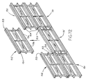
- a floor-securement system 375 (Figs. 77-78) has been developed that incorporates a modified version of the panel-mounted in-line connectors 153 and 154 to facilitate constructing a wall construction 376.
- Floor-securement system 375 includes a floor-engaging channel 380 having ends with mating in-line connectors 381 and 382 thereon that are not unlike in-line connectors 153 and 154.
- the channel 380 further includes apertured side walls 383 and 384 configured to receive off-module connectors 155 (Fig. 47).
- Floor-engaging channel 380 (Fig. 79) is constructed to securely engage base frames 160, and for this purpose includes slidably movable interlock brackets 426 for releasably engaging leveling members 386.
- the channels 380 can be shipped pre-assembled to panels 151 or shipped separate therefrom. Also, the panels 151, when assembled together, can be positively secured to the channels 380, and the channels 380 can be positively secured to the building floor, which provides a very positive construction having advantages such as resistance to damage from earthquakes and other catastrophic events.
- Floor-engaging channel 380 (Fig. 81) has a W-shaped cross section reminiscent of top frame member 171.
- Channel 380 is formed by a center flange 390, vertical intermediate side flanges 391 and 392, floor-engaging horizontal flanges 393 and 394, and vertical outer side flanges 383 and 384.
- Floor-engaging flanges 393 and 394 can be secured to a floor by adhesive, nails, and other ways known in the trade.
- Flanges 390-392 form a U-shaped section configured to slidably receive the extendable brackets 220 shown in Fig. 40 and previously described.
- a nut 397 is welded under a hole 398 near the end of center flange 390, and a screw 399 with washer/enlarged head 400 thereon is configured to threadably engage nut 397 through hole 398.
- bracket 220 When screw 399 is loosened, bracket 220 is movable between an extended position and a retracted position. Screw 399 can then be screwed into nut 397 to clampingly retain bracket 220 in the selected position.
- bracket 220 When extended, bracket 220 can be mateably engaged by an end of an aligned and adjacent floor-engaging channel 382 with the corresponding screw 399 on the mating channel being positioned in slot 228 of bracket 200.
- the corresponding screw 399 in the adjacent channel can be screwed into its nut to clampingly retain the bracket 220, thus securing the adjacent channels 380 in an aligned and interconnected position.
- the nut 397 will be welded to center flange 390, although a cinch plate could be used, like that in in-line connectors 153 and 154, if desired.
- Side flanges 383 and 384 each include a row of apertures 402 positioned generally along the lowermost edge of side flanges 383 and 384 (Fig. 81).
- the apertures 402 generally correspond to the apertures 179 on top rail member 171 (Figs. 37 and 48).
- Apertures 402 (Fig. 81) are engageable by off-module bracket 155 (Fig. 47) by inverting the off-module bracket 155 so that teeth 250 and 261 can be engaged with apertures 402 (Fig. 81) with off-module bracket 155 engaged with selected apertures 402, the apertured flanges 252/262 (Fig. 46) extend laterally and are located above the floor, where they are engageable by an in-line connector 381 on an off-module connected channel 380..
- a kickway cover 403 (Fig. 83) is configured for use with channel 380.
- Kickway cover 403 includes a resilient clip-like end 404 configured to clip attach to the top of side flange 383 (or 384).
- Kickway cover 403 further includes a horizontally extending lower leg 405 that spaces a vertical extending upper leg 406 from side flange 383.
- Upper leg 406 is biased inwardly by clip-like end 404 (Fig. 83) so that when a panel cover 334 (Fig. 80) is attached to the base panel 151, upper leg 406 presses against the panel cover 334.
- the inner surface of upper leg 406 includes hook-like features 407 and 408 for receiving tabs on an end cover for the kickway on an end panel
- kickway covers 403 can bridge or span between adjacent in-line panels 151.
- Floor-engaging channel 380 (Fig. 82) includes a plurality of support brackets 420 positioned under center flange 390 at locations generally corresponding to the predetermined locations of leveling members 386 on panel frame 151.
- Support brackets 420 each include a platform 421 supported by floor-engaging feet 422 and 423.
- Platform 421 includes a leveler receiving hole 425 defined by a frustoconically-shaped annular flange 424.
- a U-shaped interlock bracket 426 is slidably positioned on center flange 390 above platform 421.
- Interlock bracket 426 includes a longitudinally extending slot 427 (Fig. 81) and a keyhole slot 428 having an enlarged end 429 and a smaller end 430.
- Interlock bracket 426 includes a retention tab 431 engageable with an aperture 432 in center flange 390 and in aligned aperture 433 in platform 421.
- a bolt 434 is extended through slot 427 threadably into a threaded hole 435 (Fig. 82) in platform 421. Bolt 434 cooperates with tab 431 to secure interlock bracket 426 to channel 380.
- Interlock bracket 426 is movable in direction "A" (Fig. 81) to a first position wherein the enlarged end 429 of interlock bracket 426 is aligned with frustoconically-shaped hole 425 on platform 421.
- Interlock bracket 426 is further slidably movable to a second position wherein the smaller end 430 of keyhole slot 428 is aligned with frustoconically-shaped hole 425.
- Leveling member 386 (Fig. 81) includes a vertically disposed rod 440 welded to a vertical frame member such as frame member 161 on panel 151.
- a threaded nut 442 is welded to rod 440, and a threaded rod section 443 is operably engaged with nut 442 and extended therebelow.
- the lower end 444 of threaded rod 443 is tapered to mateably engage frustoconically-shaped hole 425, and has a diameter permitting it to slide through the enlarged end 429 of keyhole slot 428.
- the lower end 44 includes a narrowed section 445 with back surface 446 that is interlockingly engageable with the smaller end 430 of keyhole slot 428.
- interlock bracket 426 is moved to the first position so that the enlarged end 429 of keyhole slot 428 aligns with frustoconically-shaped hole 425.
- a panel 151 is then placed in floor-engaging channel 380 with the tapered lower end 444 of leveler 386 mateably engaging tapered hole 425 of platform 421.
- Interlock bracket 426 is then slid to the second position so that the smaller end 430 of keyhole slot 428 is aligned with tapered hole 425. In this position, interlock bracket 426 engages the back surface 446 on tapered lowered end 444 to interlockingly retain the base panel 151 to channel 386.
- the arrangement permits pre-assembly of channel 386 to base panels 151, which can be advantageous for shipping, but also optionally allows the channels 386 to be shipped separately and assembled on-site. Further, whether it is pre-assembled or assembled on-site, the channel can be interlocked to securely retain panels 151 to channel 386. This has significant value, not only to facilitate installation but also for resisting damage from earthquakes, for meeting "earthquake codes", and for resisting damage from other catastrophic events.
- a wall construction including base partition panels and stacking partition panels, interconnectable with in-line connectors, off-module connectors, and stacking connectors.
- the wall construction is connectable and reconfigurable in a variety of in-line and off-module connected arrangements, and in a variety of vertically aligned and staggered/misaligned arrangements.
Landscapes
- Engineering & Computer Science (AREA)
- Architecture (AREA)
- Civil Engineering (AREA)
- Structural Engineering (AREA)
- Physics & Mathematics (AREA)
- Electromagnetism (AREA)
- Combinations Of Kitchen Furniture (AREA)
- Installation Of Indoor Wiring (AREA)
- Assembled Shelves (AREA)
- Tents Or Canopies (AREA)
- Panels For Use In Building Construction (AREA)
- Load-Bearing And Curtain Walls (AREA)
Applications Claiming Priority (3)
| Application Number | Priority Date | Filing Date | Title |
|---|---|---|---|
| US08367802 US5746034B1 (en) | 1994-12-30 | 1994-12-30 | Partition system |
| US367802 | 1994-12-30 | ||
| EP95944656A EP0800604A4 (de) | 1994-12-30 | 1995-12-26 | Trennwandsystem |
Related Parent Applications (1)
| Application Number | Title | Priority Date | Filing Date |
|---|---|---|---|
| EP95944656A Division EP0800604A4 (de) | 1994-12-30 | 1995-12-26 | Trennwandsystem |
Publications (2)
| Publication Number | Publication Date |
|---|---|
| EP0867574A2 true EP0867574A2 (de) | 1998-09-30 |
| EP0867574A3 EP0867574A3 (de) | 2000-08-16 |
Family
ID=23448674
Family Applications (2)
| Application Number | Title | Priority Date | Filing Date |
|---|---|---|---|
| EP95944656A Withdrawn EP0800604A4 (de) | 1994-12-30 | 1995-12-26 | Trennwandsystem |
| EP98201794A Withdrawn EP0867574A3 (de) | 1994-12-30 | 1995-12-26 | Trennwandsystem für Grossraumbüros |
Family Applications Before (1)
| Application Number | Title | Priority Date | Filing Date |
|---|---|---|---|
| EP95944656A Withdrawn EP0800604A4 (de) | 1994-12-30 | 1995-12-26 | Trennwandsystem |
Country Status (9)
| Country | Link |
|---|---|
| US (11) | US5746034B1 (de) |
| EP (2) | EP0800604A4 (de) |
| JP (1) | JPH10512026A (de) |
| AU (1) | AU702876B2 (de) |
| BR (1) | BR9510185A (de) |
| CA (1) | CA2208583A1 (de) |
| CO (1) | CO4440673A1 (de) |
| MX (1) | MX9704467A (de) |
| WO (1) | WO1996021070A1 (de) |
Cited By (1)
| Publication number | Priority date | Publication date | Assignee | Title |
|---|---|---|---|---|
| WO2000015918A1 (en) * | 1998-09-11 | 2000-03-23 | Krueger International, Inc. | Knock-down panel partition system |
Families Citing this family (188)
| Publication number | Priority date | Publication date | Assignee | Title |
|---|---|---|---|---|
| US5746034B1 (en) | 1994-12-30 | 2000-10-17 | Steelcase Inc | Partition system |
| US6530181B1 (en) | 1995-12-26 | 2003-03-11 | Steelcase Development Corporation | Partition system including floor channel |
| US5890325A (en) | 1996-08-22 | 1999-04-06 | Steelcase Inc. | Reconfigurable system for subdividing building space and having minimal footprint |
| CA2225732A1 (en) * | 1996-04-26 | 1997-11-06 | Scotspine Enterprises Ltd. | Modular building system |
| US6223485B1 (en) | 1996-06-07 | 2001-05-01 | Herman Miller, Inc. | Wall panel system |
| US6341457B1 (en) | 1996-06-07 | 2002-01-29 | Herman Miller, Inc. | Light seal assembly for a wall panel system |
| US6167665B1 (en) | 1996-06-07 | 2001-01-02 | Herman Miller, Inc. | Corner post for a wall panel system |
| US5806258A (en) * | 1996-06-07 | 1998-09-15 | Haworth, Inc. | Wall panel system |
| US5852904A (en) * | 1996-08-05 | 1998-12-29 | Haworth, Inc. | Panel arrangement |
| FR2756717B1 (fr) * | 1996-12-05 | 1999-02-05 | Dior Christian Parfums | Presentoir d'articles tels que des produits cosmetiques ou des parfums |
| US5943834A (en) * | 1996-12-17 | 1999-08-31 | Steelcase Inc. | Partition construction |
| US6546684B2 (en) * | 1998-04-15 | 2003-04-15 | Steelcase Development Corporation | Partition panel |
| US5836112C1 (en) * | 1997-05-09 | 2001-05-15 | Steelcase Inc | Partition system including transaction top |
| US6158179A (en) * | 1998-03-10 | 2000-12-12 | Steelcase Development Inc. | Overhead structures for wall system |
| US6128877A (en) * | 1998-03-10 | 2000-10-10 | Steelcase Development Inc. | Variable width end panel |
| DE29804687U1 (de) * | 1998-03-16 | 1998-06-10 | Chiu, Fu Sung, Hualien | Schnellmontagewand und -stütze |
| US7208010B2 (en) | 2000-10-16 | 2007-04-24 | Conor Medsystems, Inc. | Expandable medical device for delivery of beneficial agent |
| US5930963A (en) * | 1998-06-05 | 1999-08-03 | Hon Technology Inc. | Wall panel system |
| US6374548B1 (en) | 1998-06-05 | 2002-04-23 | Trendway Corporation | Column-based workspace definition system |
| US6282854B1 (en) | 1998-06-05 | 2001-09-04 | Trendway Corporation | Frame-based workplace system |
| US6571519B1 (en) | 1998-06-05 | 2003-06-03 | Krueger International, Inc. | Panel partition system with centralized power and communication distribution |
| US6148567A (en) * | 1998-06-08 | 2000-11-21 | Haworth, Inc. | Wall panel system |
| US6082065A (en) * | 1998-08-10 | 2000-07-04 | Steelcase Development Inc. | Connector for partition system |
| US6112472A (en) * | 1998-09-14 | 2000-09-05 | Steelcase Development Inc. | Integrated furniture system including overhead framework system and partition system |
| US6247272B1 (en) | 1998-12-11 | 2001-06-19 | Steelcase Development Inc. | Curved door assembly for workstation |
| US6173536B1 (en) | 1998-12-18 | 2001-01-16 | Boyce Products, Ltd. | Workstation |
| USD426644S (en) * | 1999-01-12 | 2000-06-13 | SpAce LLC | Office workspace with shared corridor |
| USD433151S (en) * | 1999-01-12 | 2000-10-31 | SpAce LLC | Office workspace |
| US6101773A (en) * | 1999-01-13 | 2000-08-15 | Steelcase Inc. | Wire management system |
| US6272803B1 (en) * | 1999-01-28 | 2001-08-14 | Steelcase Development Corporation | Connector system for in-line connection of freestanding partitions |
| US6230445B1 (en) | 1999-04-26 | 2001-05-15 | Steelcase Development Inc. | Adjustable rack for partition system |
| GB2353541B (en) | 1999-06-04 | 2003-10-15 | Miller Herman Inc | Stackable wall panel system |
| CA2310548A1 (en) | 1999-06-04 | 2000-12-04 | Herman Miller, Inc. | Stackable wall panel system |
| US6094872A (en) * | 1999-10-08 | 2000-08-01 | Steelcase Development Inc. | Partition and floor channel construction |
| US6349911B1 (en) | 1999-12-23 | 2002-02-26 | Steelcase Development Corporation | Workplace apparatus including mounting bracket |
| US6711871B2 (en) | 2000-05-03 | 2004-03-30 | Herman Miller, Inc. | Wall panel with off-module components |
| US6557310B2 (en) | 2000-06-09 | 2003-05-06 | Smed International, Inc. | Interior space-dividing wall system |
| US6415567B1 (en) | 2000-07-07 | 2002-07-09 | Steelcase Development Corporation | Furniture post top cap attachment and trim registry |
| AUPQ995200A0 (en) * | 2000-09-07 | 2000-09-28 | Reed, Selwyn | Modular building panel |
| US6889477B1 (en) * | 2000-10-06 | 2005-05-10 | Hni Technologies Inc. | Modular wall panel construction |
| US6625935B1 (en) | 2000-10-20 | 2003-09-30 | Steelcase Development Corporation | Partition system with worktools |
| US6536858B1 (en) * | 2000-11-28 | 2003-03-25 | Steelcase Development Corporation | Elevated binder bin |
| US6561499B2 (en) | 2001-02-06 | 2003-05-13 | Lmt Mercer Group, Inc. | Picket clip |
| US6729085B2 (en) | 2001-02-09 | 2004-05-04 | Herman Miller, Inc. | Wall panel system |
| US6510663B2 (en) * | 2001-03-06 | 2003-01-28 | Steelcase Development Corporation | In-fill arrangement for post and beam furniture systems |
| US6805185B2 (en) | 2001-04-06 | 2004-10-19 | Steelcase Development Corporation | Cover panel attachment system for partitions |
| US6817478B2 (en) | 2001-05-31 | 2004-11-16 | Frank Venegas, Jr. | Modular office furniture |
| US20020184845A1 (en) * | 2001-06-06 | 2002-12-12 | Horowitz David Paul | Methods and apparatuses for securing a frame/panel to a substrate |
| US6591563B2 (en) | 2001-06-15 | 2003-07-15 | Steelcase Development Corporation | Panel system |
| US7842083B2 (en) | 2001-08-20 | 2010-11-30 | Innovational Holdings, Llc. | Expandable medical device with improved spatial distribution |
| US6684929B2 (en) | 2002-02-15 | 2004-02-03 | Steelcase Development Corporation | Panel system |
| US8393122B2 (en) * | 2002-06-06 | 2013-03-12 | Kimball International, Inc. | Partition system |
| CN1659344A (zh) | 2002-06-06 | 2005-08-24 | 金波国际公司 | 分区系统 |
| US20040031890A1 (en) * | 2002-08-13 | 2004-02-19 | Haluzak Nestor T. | Slot wall hanger |
| US6860073B2 (en) * | 2003-01-31 | 2005-03-01 | Yaw-Jiun Chien | Structure of a combinative interlocking board enclosing vertical and horizontal pipes |
| GB2424004A (en) * | 2003-05-30 | 2006-09-13 | Douglas C Ball | Work space management system |
| US20100126797A1 (en) * | 2004-02-12 | 2010-05-27 | Humphries Eric C | Panel Assembly For Traffic Noise Barrier Wall |
| US7469979B2 (en) * | 2004-03-19 | 2008-12-30 | Steelcase Inc. | Pedestal system |
| US20050279898A1 (en) * | 2004-06-21 | 2005-12-22 | Sweere Harry C | Wall mount system and method |
| EP1614820A1 (de) | 2004-07-07 | 2006-01-11 | Steelcase S.A. | Trennwandsystem für Büros und dergleichen |
| US20060032155A1 (en) * | 2004-07-23 | 2006-02-16 | Goodrich Hella Aerospace Lighting Systems Gmbh | Device for holding a partition wall on a wall in the interior of a vehicle |
| US20060032183A1 (en) * | 2004-08-16 | 2006-02-16 | Peterson Neal L | Construction member |
| USRE47132E1 (en) | 2004-08-17 | 2018-11-20 | Dirtt Environmental Solutions, Ltd | Integrated reconfigurable wall system |
| CA2516083C (en) | 2004-08-17 | 2013-03-12 | Dirtt Environmental Solutions Ltd. | Integrated reconfigurable wall system |
| US7810294B2 (en) * | 2004-09-29 | 2010-10-12 | Ig Creative Solutions, Inc. | Housing construction system |
| US7506469B2 (en) | 2004-12-22 | 2009-03-24 | Smith & Wesson Corp. | Firearm frame with configurable grip |
| US7600340B2 (en) | 2004-12-22 | 2009-10-13 | Smith & Wesson Corp. | Locking apparatus for a firearm |
| US7617628B2 (en) | 2004-12-22 | 2009-11-17 | Smith & Wesson Corp. | Fire control mechanism for a firearm |
| US7392611B2 (en) | 2004-12-22 | 2008-07-01 | Smith & Wesson Corp. | Apparatus and method for firearm takedown |
| US7703230B2 (en) | 2004-12-22 | 2010-04-27 | Smith & Wesson Corp. | Positive striker lock safety for use with a firearm |
| US7603821B2 (en) * | 2005-01-13 | 2009-10-20 | Steelcase Inc. | Partition panel system and method |
| US7464509B1 (en) * | 2005-07-15 | 2008-12-16 | Brown James C | Security wall |
| CN101512242B (zh) * | 2005-09-28 | 2012-04-25 | 汤普森科技工业公司 | 太阳能电池板阵列太阳跟踪系统 |
| US7765754B2 (en) * | 2005-12-08 | 2010-08-03 | Johnson Jay A | Ventilating spacing strip between rear surface of siding and outer surface of structure allowing horizontal air circulation |
| CA2630950C (en) * | 2005-12-20 | 2010-04-06 | Fixon E & C Co., Ltd. | Reinforcement method and reinforcement structure of the corrugated steel plate structure |
| MXPA06003796A (es) * | 2006-04-05 | 2007-10-04 | Jorge Casanova Arevalo | Mueble versatil y metodo de ensamble. |
| CN101454526B (zh) | 2006-06-01 | 2011-09-14 | 唐R·伯恩斯 | 用于安装设备的可安装于墙壁的框架结构 |
| US8033059B2 (en) * | 2006-06-09 | 2011-10-11 | Hni Technologies Inc. | Paneling system |
| WO2008041872A2 (en) * | 2006-10-06 | 2008-04-10 | Formway Furniture Limited | A screen |
| US7707795B2 (en) * | 2006-11-09 | 2010-05-04 | Haworth, Inc. | Wall panel with gusseted open frame |
| US8046957B2 (en) * | 2006-11-22 | 2011-11-01 | Steelcase Inc. | Stack-on panel assembly |
| US7841142B2 (en) * | 2006-11-22 | 2010-11-30 | Steelcase Inc. | Stack-on panel assembly |
| US7562628B2 (en) * | 2006-12-20 | 2009-07-21 | Wamble Iii John Lee | Guideway transportation system with integrated magnetic levitation suspension, stabilization and propulsion functions |
| US8803354B2 (en) | 2006-12-20 | 2014-08-12 | Unimodal Systems Llc | Modular electric generator for variable speed turbines |
| US20080148988A1 (en) * | 2006-12-20 | 2008-06-26 | John Lee Wamble | Guideway switch apparatus for magnetically levitated vehicles |
| US8171858B2 (en) * | 2006-12-20 | 2012-05-08 | Advanced Maglev Systems, Llc | Transit system vehicle guideway constructed from modular elements and using magnetic levitation for suspension and propulsion vehicles |
| US7621096B2 (en) * | 2007-04-11 | 2009-11-24 | Jeffrey Thomas Ellis | Construction blocking bracket |
| CA2590106C (en) * | 2007-05-25 | 2014-12-02 | Unifor S.P.A. | Partitioning system |
| WO2008150717A2 (en) * | 2007-06-01 | 2008-12-11 | Steelcase Development Corporation | Work space arrangements including counter assembly |
| USD599137S1 (en) | 2007-06-01 | 2009-09-01 | Steelcase Inc. | Work surface assembly |
| USD584542S1 (en) | 2007-06-07 | 2009-01-13 | Steelcase Development Corporation | Worksurface assembly |
| US8151527B2 (en) * | 2007-06-08 | 2012-04-10 | Dirtt Enviromental Solutions, Ltd. | System for providing both partial-height and full-height wall modules |
| USD581695S1 (en) | 2007-06-08 | 2008-12-02 | Steelcase Development Corporation | Worksurface assembly |
| CN101952535A (zh) * | 2007-10-15 | 2011-01-19 | 飓风布网站有限责任公司 | 天气保障系统 |
| DE102008016422B3 (de) * | 2008-03-31 | 2009-09-10 | Airbus Deutschland Gmbh | Anordnung in Rahmenbauweise zum Aufnehmen eines Vorhangs in einer Kabine eines Fahrzeugs |
| US8910435B2 (en) | 2008-05-27 | 2014-12-16 | Steelcase Inc. | Partition assembly |
| WO2009154983A2 (en) | 2008-05-27 | 2009-12-23 | Steelcase Inc. | Beam assembly |
| US8640391B2 (en) * | 2008-10-16 | 2014-02-04 | Hill-Rom Services, Inc. | Modular architectural room system |
| DE102008061851A1 (de) * | 2008-12-15 | 2010-06-17 | Deinzer Gmbh | Regaleinsatz mit variabler Breite |
| US8276302B2 (en) | 2008-12-30 | 2012-10-02 | Smith & Wesson Corp. | Manual slide and hammer lock safety for a firearm |
| US20100175919A1 (en) * | 2009-01-14 | 2010-07-15 | Boston Retail Products, Inc. | System and method for distribution of electrical power |
| US8733798B2 (en) | 2009-02-05 | 2014-05-27 | Holocom, Inc. | Conduit connector device and conduit system |
| DE102009022479B4 (de) * | 2009-02-20 | 2022-05-19 | Isinger + Merz Gmbh | Mobiles modulares Wandsystem |
| US8327589B2 (en) * | 2009-03-05 | 2012-12-11 | Raspberry Med, Inc. | Wall-mounted modular accessory system |
| US8474193B2 (en) | 2009-03-05 | 2013-07-02 | Raspberry Med, Inc. | Wall-mounted modular accessory system |
| US8313067B2 (en) | 2009-12-15 | 2012-11-20 | Welch Allyn, Inc. | Pole shaft coupling assembly and related method |
| US9009011B2 (en) | 2009-12-18 | 2015-04-14 | Patco, Inc. | Integrated construction platform |
| WO2011075394A1 (en) * | 2009-12-18 | 2011-06-23 | Patco, Llc | Panelized structural system for building construction |
| US8688411B2 (en) | 2009-12-18 | 2014-04-01 | John Louis Vanker | Method and system of using standardized structural components |
| US8689705B2 (en) | 2010-06-02 | 2014-04-08 | Steelcase, Inc. | Reconfigurable table assemblies |
| US9210999B2 (en) | 2010-06-02 | 2015-12-15 | Steelcase Inc. | Frame type table assemblies |
| US8667908B2 (en) | 2010-06-02 | 2014-03-11 | Steelcase Inc. | Frame type table assemblies |
| US9185974B2 (en) | 2010-06-02 | 2015-11-17 | Steelcase Inc. | Frame type workstation configurations |
| US8950132B2 (en) | 2010-06-08 | 2015-02-10 | Innovative Building Technologies, Llc | Premanufactured structures for constructing buildings |
| US9493940B2 (en) | 2010-06-08 | 2016-11-15 | Innovative Building Technologies, Llc | Slab construction system and method for constructing multi-story buildings using pre-manufactured structures |
| DE102010047380B3 (de) * | 2010-10-05 | 2011-11-24 | Lang Technik Gmbh | Linearer mechanischer Schnellverschluß |
| WO2012050554A1 (en) | 2010-10-11 | 2012-04-19 | Ig Creative Solutions, Inc. | Housing construction system |
| US8434629B2 (en) * | 2011-04-08 | 2013-05-07 | Clairson Inc. | Adjustable shelving system with overlapping tracks |
| US8882065B2 (en) | 2011-04-26 | 2014-11-11 | Kimball International, Inc. | Two piece track assembly |
| US8967054B2 (en) | 2011-06-03 | 2015-03-03 | Kimball International, Inc. | Office desking system |
| EP2718511B1 (de) * | 2011-06-11 | 2016-10-12 | Dirtt Environmental Solutions, Ltd. | Modulares wandstecksystem |
| US9249567B2 (en) | 2011-07-26 | 2016-02-02 | Haworth, Inc. | Reusable architectural wall |
| WO2013101298A1 (en) | 2011-12-28 | 2013-07-04 | Dirtt Environmental Solutions Inc. | Modular walls incorporating recessed, extendable furniture |
| US8590246B2 (en) * | 2012-01-04 | 2013-11-26 | Daniel Coccagna | Masonry spacer |
| US9010033B2 (en) | 2012-01-18 | 2015-04-21 | Kimball International, Inc. | Wall rail system |
| WO2013188211A1 (en) * | 2012-06-11 | 2013-12-19 | Dirtt Environmental Solutions Inc. | Modular building construction systems and methods |
| US12376677B1 (en) | 2012-10-10 | 2025-08-05 | Steelcase Inc. | Ergonomic seating system, tilt-lock control and remote powering method and apparatus |
| US9427083B2 (en) | 2012-12-06 | 2016-08-30 | Herman Miller, Inc. | Furniture docking system |
| US9032682B2 (en) | 2012-12-10 | 2015-05-19 | Target Brands, Inc. | Free-standing wall |
| US8973315B2 (en) * | 2012-12-21 | 2015-03-10 | Milgard Manufacturing Incorporated | Window trim system |
| EP3044388A4 (de) * | 2013-09-09 | 2017-03-29 | DIRTT Environmental Solutions, Ltd. | Durchgehende regalwandanordnung |
| US9049905B2 (en) * | 2013-10-23 | 2015-06-09 | GM Global Technology Operations LLC | Clip and coupling assembly |
| SE540168C2 (en) | 2014-01-22 | 2018-04-17 | Ab Edsbyverken | A partition screen, a partition screen system and a method of making the partition screen |
| US11085184B2 (en) | 2014-02-20 | 2021-08-10 | Dirtt Environmental Solutions Ltd. | Interface for mounting interchangable components |
| NL1040682C2 (en) * | 2014-02-24 | 2015-08-25 | Hunter Douglas Ind Bv | Building panel for ceilings or walls. |
| CN104032867A (zh) * | 2014-06-18 | 2014-09-10 | 深圳市建艺装饰集团股份有限公司 | 一种方通龙骨隔音墙及其施工方法 |
| CN107148540B (zh) | 2014-08-30 | 2019-11-26 | 创新建筑科技公司 | 在建筑物中使用的地板和天花板面板 |
| US10364572B2 (en) | 2014-08-30 | 2019-07-30 | Innovative Building Technologies, Llc | Prefabricated wall panel for utility installation |
| US10041289B2 (en) * | 2014-08-30 | 2018-08-07 | Innovative Building Technologies, Llc | Interface between a floor panel and a panel track |
| WO2016032540A1 (en) | 2014-08-30 | 2016-03-03 | Innovative Building Technologies, Llc | Prefabricated demising and end walls |
| US10260250B2 (en) | 2014-08-30 | 2019-04-16 | Innovative Building Technologies, Llc | Diaphragm to lateral support coupling in a structure |
| CN105696754A (zh) * | 2014-12-10 | 2016-06-22 | 顺和系统有限公司 | 模块化装饰墙面板 |
| DE102015108660A1 (de) * | 2015-06-01 | 2016-12-01 | Dorma Deutschland Gmbh | Trennwandmodul einer Trennwand |
| JP6761744B2 (ja) * | 2015-11-30 | 2020-09-30 | エアバス オペレーションズ ゲーエムベーハーAirbus Operations GmbH | 立体骨組構築キット及び立体骨組 |
| EP3173953A1 (de) * | 2015-11-30 | 2017-05-31 | Airbus Operations GmbH | Computerimplementiertes verfahren für raumrahmenkonstruktion, fahrzeugrahmen-konstruktionskit und raumrahmen |
| US10430548B2 (en) | 2015-11-30 | 2019-10-01 | Airbus Operations Gmbh | Computer-implemented method for space frame design, space frame construction kit and space frame |
| CA2932531C (en) | 2016-02-10 | 2024-01-09 | Dirtt Environmental Solutions, Ltd. | Embedded furniture having retractible legs with lighting |
| CN109073240B (zh) | 2016-03-07 | 2021-07-20 | 创新建筑技术有限责任公司 | 用于建筑物的无平板楼面系统的楼面和天花板面板 |
| CA3015811C (en) | 2016-03-07 | 2020-12-29 | Innovative Building Technologies, Llc | Prefabricated demising wall with external conduit engagement features |
| EP4039905A1 (de) | 2016-03-07 | 2022-08-10 | Innovative Building Technologies, LLC | Vormontierte wandplatte zur versorgungsanlageninstallation und bauverfahren |
| MX2018010275A (es) | 2016-03-07 | 2019-02-11 | Innovative Building Tech Llc | Ensambles de impermeabilizacion y paneles de pared prefabricados que incluyen los mismos. |
| WO2017197395A1 (en) | 2016-05-13 | 2017-11-16 | Steelcase Inc. | Multi-tiered workstation assembly |
| US10517392B2 (en) | 2016-05-13 | 2019-12-31 | Steelcase Inc. | Multi-tiered workstation assembly |
| USD816355S1 (en) * | 2016-05-18 | 2018-05-01 | Knoll, Inc. | Panel system |
| CN105863116B (zh) * | 2016-05-25 | 2018-03-06 | 深圳市建艺装饰集团股份有限公司 | 一种双层方钢通隔音墙结构及其安装方法 |
| EP3322863A4 (de) | 2016-06-10 | 2019-05-01 | DIRTT Environmental Solutions, Ltd. | Glassubstrate mit berührungsbildschirmtechnologie |
| WO2017214425A1 (en) | 2016-06-10 | 2017-12-14 | Dirtt Environmental Solutions, Inc. | Wall system with electronic device mounting assembly |
| CA3030282A1 (en) | 2016-07-08 | 2018-01-11 | Dirtt Environmental Solutions, Inc. | Low-voltage smart glass |
| US9982427B2 (en) * | 2016-09-06 | 2018-05-29 | Cooper Technologies Company | Concrete deck insert |
| KR101753540B1 (ko) * | 2016-11-25 | 2017-07-04 | 황영준 | 드로잉 카페 |
| US10323428B2 (en) | 2017-05-12 | 2019-06-18 | Innovative Building Technologies, Llc | Sequence for constructing a building from prefabricated components |
| US10724228B2 (en) | 2017-05-12 | 2020-07-28 | Innovative Building Technologies, Llc | Building assemblies and methods for constructing a building using pre-assembled floor-ceiling panels and walls |
| US11098475B2 (en) | 2017-05-12 | 2021-08-24 | Innovative Building Technologies, Llc | Building system with a diaphragm provided by pre-fabricated floor panels |
| US10487493B2 (en) | 2017-05-12 | 2019-11-26 | Innovative Building Technologies, Llc | Building design and construction using prefabricated components |
| US10501933B2 (en) * | 2017-05-26 | 2019-12-10 | Duraframe, LLC | Weather resistant temporary wall system and method |
| GB2563059A (en) * | 2017-06-02 | 2018-12-05 | Ccomm Group Ltd | A media wall |
| US10098460B1 (en) * | 2017-08-23 | 2018-10-16 | Clairson, Inc. | Shelf brackets, hang rod brackets, and storage systems including the same |
| TWM555164U (zh) * | 2017-10-12 | 2018-02-11 | 力坊科技股份有限公司 | 鋁合金櫥櫃板之結構改良 |
| CN107829510B (zh) * | 2017-10-25 | 2019-07-26 | 阳地钢(上海)装配式建筑股份有限公司 | 具有复合型环保墙板的装配式房屋 |
| US12252380B1 (en) * | 2018-04-27 | 2025-03-18 | California Manufacturing & Engineering Company, Llc | Work platform having attached movable work step |
| US20190330034A1 (en) * | 2018-04-27 | 2019-10-31 | California Manufacturing & Engineering Company, Llc | Work platform with extension deck and work step |
| CN110565835A (zh) * | 2018-06-06 | 2019-12-13 | 北新集团建材股份有限公司 | 局部增强型装配式墙体 |
| KR102649223B1 (ko) | 2018-11-14 | 2024-03-20 | 이노베이티브 빌딩 테크놀러지스 엘엘씨 | 모듈식 계단통 및 엘리베이터 샤프트 시스템 및 방법 |
| US11608634B2 (en) * | 2019-05-03 | 2023-03-21 | Watson Furniture Group, Inc. | Flexible workspace partition system |
| CN110241948B (zh) * | 2019-05-22 | 2020-09-08 | 安徽森泰木塑集团股份有限公司 | 一种模块化墙体移位固定方式 |
| DK3747313T3 (da) * | 2019-06-05 | 2022-05-09 | Rol Ergo Ab | Fremgangsmåde til at fremstille en bundplade til et bord og et produkt deraf. |
| US11441313B2 (en) | 2019-06-07 | 2022-09-13 | Knoll, Inc. | Enclosure assembly apparatus and method for forming same |
| US12434267B2 (en) * | 2019-07-30 | 2025-10-07 | Dirtt Environmental Solutions Ltd. | Warp resistant panels |
| CN111926989B (zh) * | 2020-07-17 | 2021-12-03 | 余选清 | 一种组合式保温砌块 |
| GB2597752B (en) | 2020-08-03 | 2025-02-12 | Urben Tech Holdings Ltd | A display unit |
| US10989237B1 (en) | 2020-09-04 | 2021-04-27 | Robert J. Wittsche | System for extending the height of cubicle wall panel |
| US11718985B2 (en) * | 2020-10-14 | 2023-08-08 | Isaac Walker | Construction block |
| US11647832B2 (en) | 2021-02-16 | 2023-05-16 | Newage Products Inc. | Cabinet assembly |
| JP7687921B2 (ja) * | 2021-09-22 | 2025-06-03 | 株式会社オカムラ | 間仕切り装置 |
| JP7687920B2 (ja) * | 2021-09-22 | 2025-06-03 | 株式会社オカムラ | パネルユニット、間仕切り装置 |
| CN115126188B (zh) * | 2022-08-12 | 2024-02-20 | 安必安新材料(广东)有限公司 | 一种自饰面架空地板及其安装方法 |
| WO2024042473A1 (en) * | 2022-08-24 | 2024-02-29 | Steelcase Inc. | Wall panel system |
| US20240102339A1 (en) * | 2022-09-22 | 2024-03-28 | A&C Future, Inc. | Removable window for easy changing room layout |
Family Cites Families (188)
| Publication number | Priority date | Publication date | Assignee | Title |
|---|---|---|---|---|
| US34381A (en) * | 1862-02-11 | Improvement in fancy-looms | ||
| US1876528A (en) * | 1932-09-06 | Intebior building wall structure | ||
| US735618A (en) * | 1902-03-31 | 1903-08-04 | David W Kendall | Furniture-coupling. |
| US726732A (en) * | 1902-12-31 | 1903-04-28 | William E Nelson | Fastening device for furniture. |
| US1724821A (en) * | 1927-11-23 | 1929-08-13 | Hauserman Co E F | Sectional partition unit |
| US1959135A (en) * | 1929-01-07 | 1934-05-15 | Emmet S Miller | Wall construction |
| US1990259A (en) * | 1932-07-20 | 1935-02-05 | Hugo L Walters | Building wall structure |
| US2049278A (en) | 1933-01-03 | 1936-07-28 | Stephen E Toussaint | Building construction |
| US2040385A (en) * | 1933-10-19 | 1936-05-12 | Johnis Manville Corp | Wall assembly |
| US2121213A (en) * | 1934-03-29 | 1938-06-21 | Martin Parry Corp | Interior paneling |
| US2044637A (en) | 1935-02-04 | 1936-06-16 | Rostone Inc | Building construction |
| US2232510A (en) * | 1939-05-06 | 1941-02-18 | Charles W Buckham | Building structure |
| US2576865A (en) * | 1948-10-18 | 1951-11-27 | Grand Rapids Store Equip Co | Bracket and lock therefor |
| US2741449A (en) * | 1952-02-08 | 1956-04-10 | Heseiov Simon | Adjustable shelving upright and bracket |
| FR1055464A (fr) * | 1952-05-05 | 1954-02-18 | Cloison mobile pour locaux d'habitation et divers | |
| GB714002A (en) * | 1952-05-17 | 1954-08-18 | Cedric William Taylor Pochin | Improvements in and relating to partitions for buildings and the like |
| US2849756A (en) * | 1953-07-02 | 1958-09-02 | Airtherm Mfg Company | Insulation clip |
| US2915151A (en) * | 1957-12-04 | 1959-12-01 | Gen Steel Products Corp | Partition structures |
| US3065575A (en) * | 1958-06-06 | 1962-11-27 | Bernard W Downs | Wall structure for buildings |
| US3066770A (en) * | 1959-02-12 | 1962-12-04 | Ralph S Millard | Demountable metal partitions |
| US3001615A (en) * | 1959-04-24 | 1961-09-26 | Wheeling Steel Corp | Studding |
| US3135026A (en) * | 1960-01-11 | 1964-06-02 | Fridolph Doris Irene | Movable partition structure |
| US3195698A (en) * | 1960-04-11 | 1965-07-20 | H B Rothbard | Partition structures |
| US3045784A (en) * | 1960-05-02 | 1962-07-24 | Porcel Engineering Company | Metallic wall construction |
| US3093218A (en) * | 1960-08-01 | 1963-06-11 | Donald H Peterson | Internal building partition structures |
| US3097822A (en) * | 1960-11-25 | 1963-07-16 | Warren R Attwood | Shelf bracket and clips |
| US3087702A (en) * | 1961-02-17 | 1963-04-30 | Gen Fireproofing Co | Shelf support |
| US3101817A (en) * | 1961-08-11 | 1963-08-27 | Radek John | Wall panel structure |
| US3090164A (en) * | 1961-09-25 | 1963-05-21 | United States Gypsum Co | Wall construction and resilient runner therefor |
| US3180459A (en) * | 1962-06-12 | 1965-04-27 | Liskey Aluminum | Demountable sectional partition |
| US3199822A (en) * | 1962-06-21 | 1965-08-10 | Garcy Corp | Support clip |
| GB1098851A (en) * | 1963-10-03 | 1968-01-10 | Hille & Company Ltd S | Built-in furniture component |
| US3290846A (en) * | 1964-04-09 | 1966-12-13 | Mader Cabinet Works | Wall facing |
| BE637777A (de) * | 1964-08-18 | |||
| US3332182A (en) * | 1964-12-03 | 1967-07-25 | Interstate Ind Inc | Partition stud and spring assembly |
| NL128087C (de) * | 1965-07-12 | |||
| US3370391A (en) * | 1965-09-07 | 1968-02-27 | Kaiser Gypsum Company Inc | Resilient structural beam |
| US3408781A (en) * | 1966-02-14 | 1968-11-05 | Mills Company | Partition and method of tilting into position |
| FR1484827A (fr) * | 1966-05-06 | 1967-06-16 | Fabrication D Isolants Et Reve | Dispositif et mode d'assemblage et de fixation de panneaux de revêtement muraux |
| US3391795A (en) * | 1966-06-23 | 1968-07-09 | Interlake Steel Corp | Drive-in pallet rack |
| US3353314A (en) * | 1966-06-24 | 1967-11-21 | Bally Case And Cooler Inc | Insulated panel having joined connectors |
| US3425568A (en) * | 1966-08-18 | 1969-02-04 | Alto O Albright | Wall mounted educational device |
| US3392497A (en) * | 1966-10-21 | 1968-07-16 | Delron Company Inc | Modular enclosure with clamp joined panels |
| DE1779347A1 (de) * | 1967-08-12 | 1971-09-16 | Ital Bed Cost Letti Affini | Aus einer Wand ausziehbare Trennwand fuer Krankenhaeuser u.dgl. |
| US3514883A (en) * | 1968-08-12 | 1970-06-02 | Alto O Albright | Pivotal display panel installation |
| US3514794A (en) * | 1968-08-12 | 1970-06-02 | Ital Bed Cost Letti Affini | Bed units |
| US3565381A (en) * | 1968-10-21 | 1971-02-23 | Earl J Oliver | Bracket structure |
| US3561182A (en) * | 1969-03-11 | 1971-02-09 | Joseph Madl | Panel support system for building structures |
| US3571987A (en) * | 1969-04-16 | 1971-03-23 | United States Steel Corp | Wall paneling and modular furniture system |
| US3705002A (en) * | 1969-08-06 | 1972-12-05 | Giovanni Varlonga | Bearing sections for the covering with marble plates, panels and the like of walls both uninterrupted and interrupted by doors, windows and the like |
| US3638376A (en) * | 1970-01-05 | 1972-02-01 | Hough Mfg Corp | Portable partition |
| US3686805A (en) * | 1970-03-20 | 1972-08-29 | Ital Bed Cost Letti Affini | Assemblies for mounting panels on walls |
| US3885361A (en) * | 1970-11-19 | 1975-05-27 | Perfect Module Systems Inc | Building wall panel leveler device |
| US3745732A (en) * | 1971-08-05 | 1973-07-17 | Superior Industries | Demountable partition system |
| US3834093A (en) * | 1972-03-14 | 1974-09-10 | Steelcase Inc | Panel jointure system |
| US3798865A (en) * | 1972-03-17 | 1974-03-26 | Integrated Ceilings Inc | Grid support structure and clip means therefor |
| US3811575A (en) * | 1972-04-05 | 1974-05-21 | R Boegehold | System of constructing display racking and shelving |
| US3894377A (en) * | 1974-01-21 | 1975-07-15 | Modular Syst | Fastener clip |
| US3958386A (en) * | 1974-04-08 | 1976-05-25 | Pollock Eugene B | Building structural system |
| US3989399A (en) * | 1974-10-04 | 1976-11-02 | Slowbe Joseph A | Structural joint assembly |
| SE393657B (sv) | 1974-11-12 | 1977-05-16 | Sapa Ab | Anordning vid beslag for fastsettning av ihaliga profiler |
| US4018167A (en) * | 1975-05-02 | 1977-04-19 | Reflector Hardware Corporation | Preassembled bracket and shelf assembly |
| US4060294A (en) * | 1975-09-22 | 1977-11-29 | Haworth Mfg., Inc. | Wall panel with prewired power system |
| JPS52102814U (de) * | 1976-02-02 | 1977-08-04 | ||
| DE2623814A1 (de) | 1976-05-28 | 1977-12-08 | Albrecht Streib | Loesbare verbindung zweier teile eines gestells |
| JPS574175Y2 (de) * | 1976-08-11 | 1982-01-26 | ||
| US4277920A (en) * | 1976-09-28 | 1981-07-14 | Panelfold Doors, Inc. | Portable and operable wall systems |
| US4204375A (en) * | 1976-09-30 | 1980-05-27 | Harter Corporation | Frame construction for a divider wall |
| US4121645A (en) * | 1977-05-06 | 1978-10-24 | Joseph Henry Behr | Room divider panel assembly |
| GB1600990A (en) * | 1977-11-18 | 1981-10-21 | Ashelwood Prod Pty | Sectional screens |
| US4198913A (en) * | 1978-05-26 | 1980-04-22 | Haworth Mfg., Inc. | Component locking device |
| US4224769A (en) * | 1978-06-12 | 1980-09-30 | Hauserman Limited | Space divider system |
| US4255611A (en) * | 1978-10-20 | 1981-03-10 | Herman Miller, Inc. | Energy distribution system for enclosed areas |
| GB2060022A (en) | 1979-09-26 | 1981-04-29 | Wilkinsons Furniture Ltd | Frame members and a screen constructed from such frame members |
| US4429934A (en) * | 1979-09-27 | 1984-02-07 | Steelcase Inc. | Panel wiring system |
| US4771583A (en) * | 1979-10-03 | 1988-09-20 | Hauserman, Inc. | Space divider system |
| US4356674A (en) | 1980-03-31 | 1982-11-02 | Herman Miller, Inc. | Free-standing space divider assembly with acoustic upper end border |
| FR2508524A1 (fr) * | 1981-06-25 | 1982-12-31 | Mors Jean Bouchon Entr Elect | Ensemble modulaire de construction d'un emplacement d'exposition |
| NZ197507A (en) * | 1980-07-02 | 1984-11-09 | Stirling Wilson M | Slidable clip:method of panelling using clips,reentrant flanged channels,and t & g boards |
| US4391069A (en) * | 1980-10-23 | 1983-07-05 | The Columbus Show Case Company | Free standing wall |
| US4391073A (en) * | 1980-12-12 | 1983-07-05 | Rosemount Office Systems, Inc. | Movable panel assembly |
| US4378925A (en) * | 1981-03-10 | 1983-04-05 | Lingo Manufacturing Company | T-Bracket shelf assembly |
| JPS6134824Y2 (de) * | 1981-04-09 | 1986-10-09 | ||
| JPH0220329Y2 (de) * | 1981-05-21 | 1990-06-04 | ||
| FR2518192B1 (fr) | 1981-12-10 | 1985-09-27 | Mouza Ets | Dispositif d'assemblage de deux pieces, telles que deux profiles realises par exemple en alliage leger |
| US4567699A (en) * | 1982-01-20 | 1986-02-04 | Mcclellan Thomas A | Prefabricated panel and building system |
| US4449337A (en) * | 1982-03-15 | 1984-05-22 | Stow Davis Furniture Company | Adjustable base for office landscaping system |
| US4555880A (en) * | 1982-03-15 | 1985-12-03 | Stow & Davis Furniture Company | Adjustable base for office landscaping system |
| US4512122A (en) * | 1982-05-03 | 1985-04-23 | Kason Industries Inc. | Panel fastener system |
| US4535577A (en) * | 1982-12-15 | 1985-08-20 | Global Upholstery Company Limited | Office panelling system |
| US4712336A (en) * | 1983-04-18 | 1987-12-15 | Backer Bruce E | Interconnecting "full bleed" modular panel and connective hardware system to form a variety of exhibit and office interior enclosures |
| AU572830B2 (en) * | 1983-04-19 | 1988-05-19 | Geoffrey Ballantyne Ashton | Sectional screens |
| US4578914A (en) * | 1983-06-10 | 1986-04-01 | Wesley Staples | Interior wall construction |
| US4567698A (en) * | 1983-12-13 | 1986-02-04 | Knoll International, Inc. | Space divider system |
| JPS60108619U (ja) * | 1983-12-28 | 1985-07-24 | ワイケイケイ株式会社 | カ−テンウオ−ルユニツトの連結装置 |
| GB2153870B (en) * | 1983-12-28 | 1987-04-29 | Yoshida Kogyo Kk | Prefabricated curtain wall assembly having both window and spandrel units |
| US4883330A (en) * | 1984-06-08 | 1989-11-28 | Knoll International, Inc. | Spine assembly |
| US4619486A (en) * | 1984-06-08 | 1986-10-28 | Knoll International, Inc. | Spine assembly |
| US4685255A (en) * | 1984-09-10 | 1987-08-11 | Herman Miller, Inc. | Work space management system |
| US4876835A (en) * | 1984-09-10 | 1989-10-31 | Herman Miller, Inc. | Work space management system |
| EP0181478A3 (de) * | 1984-10-05 | 1986-05-28 | Takeda Chemical Industries, Ltd. | Härtbare Harzzusammensetzungen sowie deren Verwendung |
| US4730740A (en) * | 1984-10-17 | 1988-03-15 | Russell William, Ltd. | Display system |
| US4646211A (en) * | 1984-11-19 | 1987-02-24 | Hill-Rom Company, Inc. | Service outlet wall and rail system for use thereon |
| US4831791A (en) * | 1984-11-20 | 1989-05-23 | Hauserman, Inc. | Space divider system |
| GB8510909D0 (en) * | 1985-04-30 | 1985-06-05 | Vickers Plc | Office screens & partitions |
| USRE34381E (en) | 1985-05-29 | 1993-09-21 | Axial locking device | |
| GB2175949B (en) * | 1985-05-29 | 1988-05-25 | Austen Barnes | Axial locking device |
| US4625483A (en) * | 1985-06-03 | 1986-12-02 | Aspects, Inc. | Connector system for furniture panels |
| GB2176220B (en) * | 1985-06-11 | 1988-09-14 | Alan Raymond Notley | Screen for partitioning open floor areas |
| US4783034A (en) * | 1985-08-13 | 1988-11-08 | General Datacomm, Inc. | Slide lock mechanism |
| US4660339A (en) * | 1985-11-20 | 1987-04-28 | Felix Paz | Wall system |
| US4716699A (en) * | 1986-01-17 | 1988-01-05 | Rostec Industries | Wall panels with single load-bearing connector posts |
| US4651484A (en) * | 1986-03-31 | 1987-03-24 | National Gypsum Company | Furniture channel |
| AU581818B2 (en) * | 1986-05-26 | 1989-03-02 | Richard Howard | A computer workstation |
| FR2599404B1 (fr) * | 1986-05-28 | 1988-08-12 | Guerin Georges | Paroi a doubles-panneaux |
| US4709517A (en) * | 1986-06-02 | 1987-12-01 | Architectural Wall Systems, Inc. | Floor-to-ceiling wall system |
| US4862659A (en) * | 1986-06-06 | 1989-09-05 | Haworth, Inc. | Wall panel with accessible interior channels for laying in of cables |
| DE3628672A1 (de) * | 1986-08-23 | 1988-02-25 | Dorn Uwe Gmbh | Mobiles plattenelement mit integrierter elektrischer stromverteilerschiene |
| JPH0433290Y2 (de) * | 1987-03-31 | 1992-08-10 | ||
| IT1222449B (it) * | 1987-08-06 | 1990-09-05 | Coopsette Srl | Parete divisoria interna componibile con proprieta' schermanti al fuoco e simili |
| AU617653B2 (en) * | 1987-08-26 | 1991-12-05 | Bryan J. Beaulieu | Fastening device for support structures |
| FR2620492B1 (fr) * | 1987-09-11 | 1990-01-12 | Aerospatiale | Systeme d'accouplement de deux corps par exemple un chariot et un poste d'usinage |
| US5239798A (en) * | 1987-10-30 | 1993-08-31 | Kajima Corporation | External wall panel and mounting structure thereof |
| GB2212186A (en) * | 1987-11-11 | 1989-07-19 | Environmental Panelling Syst | Demountable panelling |
| CH671597A5 (de) * | 1988-01-28 | 1989-09-15 | Mantel Embru Werke | |
| US4837988A (en) * | 1988-01-29 | 1989-06-13 | National Gypsum Company | Universal secondary stud |
| US5048243A (en) * | 1988-03-11 | 1991-09-17 | Ward John D | Earthquake restraint mechanism |
| US4841699A (en) * | 1988-04-05 | 1989-06-27 | Haworth, Inc. | Wall panel with accessible interior channels for laying in of cables |
| US4928467A (en) * | 1988-05-13 | 1990-05-29 | Hintsa Roy A | Panel fastener |
| US4833849A (en) * | 1988-06-15 | 1989-05-30 | Williams Mark F | Building enclosure assemblies |
| US5394658A (en) * | 1988-07-29 | 1995-03-07 | Schreiner; Charles P. | Free standing modular furniture and wall system |
| US4944122A (en) * | 1988-10-04 | 1990-07-31 | Wendt Alan C | Horizontally oriented demountable partition system |
| US4905428A (en) * | 1988-11-16 | 1990-03-06 | Sykes Christopher C | Partition structures and frame elements therefor |
| US5062246A (en) * | 1988-11-16 | 1991-11-05 | Sykes Christopher C | Partition structures and frame elements therefor |
| US5005325A (en) * | 1988-11-23 | 1991-04-09 | The Shaw-Walker Company | Position adjustment leg for partition panel assembly |
| EP0371153B1 (de) * | 1988-11-28 | 1992-05-13 | Exibelco GmbH | Verbindungselement |
| US4991368A (en) * | 1989-01-06 | 1991-02-12 | Amstore Corporation | Wall system |
| DE3902385A1 (de) * | 1989-01-27 | 1990-08-02 | Mba Design & Display Product G | Trennwandung, insbesondere fuer messehallen |
| US4942805A (en) * | 1989-02-02 | 1990-07-24 | Teknion Furniture Systems Inc. | Ventilated panel |
| US5220871A (en) | 1989-02-07 | 1993-06-22 | Steelcase Inc. | Modular furniture |
| US4918886A (en) * | 1989-05-31 | 1990-04-24 | Harpers | Raceway system for modular wall panels |
| US4942713A (en) * | 1989-06-09 | 1990-07-24 | Harter Corporation | Interconnecting structure for releasably securing successive panels in a relocatable wall |
| US4947601A (en) * | 1989-07-18 | 1990-08-14 | Glen O'brien Movable Partition Co., Inc. | Wall panel trim system and method |
| DE3930161C1 (de) * | 1989-09-09 | 1990-09-13 | Rittal-Werk Rudolf Loh Gmbh & Co Kg, 6348 Herborn, De | |
| JPH03140539A (ja) * | 1989-10-26 | 1991-06-14 | Herman Miller Inc | 仕事空間管理システム |
| US5054255A (en) * | 1989-10-27 | 1991-10-08 | Herbert Maninfior Design/Engineering | Wall panel construction and connection system |
| US5038534A (en) * | 1989-12-18 | 1991-08-13 | Pollock Gordon J | Unitary panel module and connector |
| US5214889A (en) * | 1990-01-18 | 1993-06-01 | Herman Miller, Inc. | Electrified wall panel system |
| US5086597A (en) * | 1990-02-20 | 1992-02-11 | Herman Miller, Inc. | Work space management system hallway wall arrangement |
| US5129202A (en) | 1990-02-23 | 1992-07-14 | Herman Miller, Inc. | Fabric tile construction |
| US5174086A (en) | 1990-02-23 | 1992-12-29 | Herman Miller, Inc. | Method for making a fabric file construction |
| JP2513163B2 (ja) * | 1990-02-28 | 1996-07-03 | コクヨ株式会社 | 可動間仕切壁 |
| US5025603A (en) * | 1990-04-04 | 1991-06-25 | Herman Miller, Inc. | Modular space dividing panels having wire management channels |
| US5040345A (en) * | 1990-04-27 | 1991-08-20 | Gilmour Michael F | Stud clip for allowing vertical floating movement of a floor or roof structure |
| US5155955A (en) * | 1990-05-02 | 1992-10-20 | Westinghouse Electric Corp. | Frame based office space dividing system |
| IT1240376B (it) * | 1990-05-21 | 1993-12-10 | C.O.M.S. Coop. A.R.L. | Procedimento per la produzione di sistemi di arredamento per ufficio e gruppo di arredamento per ufficio |
| US5117599A (en) * | 1990-05-31 | 1992-06-02 | Allsteel Inc. | Panel connector arrangement for office furniture demountable wall panel space divider systems |
| US5142832A (en) * | 1990-09-14 | 1992-09-01 | Bill Branham Designs, Ltd. | Wall mounting system |
| US5187908A (en) * | 1990-10-22 | 1993-02-23 | La-Z-Boy Chair Company | Modular wall panel interconnection apparatus and method |
| US5176462A (en) * | 1990-11-30 | 1993-01-05 | Chen Kuei Feng | Built-up screen coupling structure |
| US5209035A (en) * | 1991-01-10 | 1993-05-11 | Steelcase Inc. | Utility panel system |
| US5313752A (en) * | 1991-01-11 | 1994-05-24 | Fero Holdings Limited | Wall framing system |
| USD350401S (en) | 1991-04-09 | 1994-09-06 | NordProfil B.V. | Combined T-bar and suspension bracket for a ceiling grid |
| US5134826A (en) * | 1991-04-23 | 1992-08-04 | Precision Manufacturing, Inc. | Structural panel connector for space dividing system |
| US5214890A (en) * | 1991-04-29 | 1993-06-01 | Teknion Furniture Systems | Office panel with lay-in communication cable capability |
| US5184441A (en) * | 1991-05-14 | 1993-02-09 | Allsteel Inc. | Top cap with snap-in accent strip for wall panels |
| US5175969A (en) * | 1991-06-06 | 1993-01-05 | Steelcase Inc. | Partition panel |
| RU2010112C1 (ru) | 1991-06-27 | 1994-03-30 | Завод "Мосметаллоконструкция" | Замок для соединения профилей |
| US5184444A (en) | 1991-08-09 | 1993-02-09 | Aec-Able Engineering Co., Inc. | Survivable deployable/retractable mast |
| US5203132A (en) * | 1991-09-17 | 1993-04-20 | Smolik Robert A | Wall assembly |
| US5177917A (en) * | 1991-12-02 | 1993-01-12 | Castillo Haucke J M Del | Modular panel wall structure |
| IT1254774B (it) * | 1992-02-11 | 1995-10-11 | Bruno Degrada | Struttura per la realizzazione di pareti divisorie di vani particolarmente per sale operatorie e simili |
| US5309686A (en) * | 1992-02-19 | 1994-05-10 | Kimball International, Inc. | Work space partition system |
| US5277007A (en) * | 1992-05-04 | 1994-01-11 | Teknion Furniture Systems | Office panel with top lay-in passageway |
| US5241796A (en) * | 1992-05-04 | 1993-09-07 | Teknion Furniture Systems | Securing bracket |
| US5277005A (en) * | 1992-05-04 | 1994-01-11 | Teknion Furniture Systems | Free-standing partitioning panel |
| US5377466A (en) * | 1992-05-29 | 1995-01-03 | Haworth, Inc. | Separable post/panel system |
| US5400560A (en) | 1992-06-05 | 1995-03-28 | Teknion Furniture Systems | Office panel element configuration |
| DE4219717A1 (de) | 1992-06-17 | 1993-12-23 | Rodwyl Trading Ag Allschwil | Verbindungselement |
| US5417020A (en) | 1992-08-12 | 1995-05-23 | Dobija; Michael J. | Wall system providing an array of individual panels |
| AU665471B2 (en) * | 1992-12-07 | 1996-01-04 | Kenneth David Anstey | Office furniture and fittings |
| US5394668A (en) * | 1993-02-12 | 1995-03-07 | Herman Miller, Inc. | Panel extension assembly |
| US5437426A (en) * | 1993-06-25 | 1995-08-01 | Steelcase Inc. | Bracket arrangement for hang-on furniture unit |
| CA2101190C (en) * | 1993-10-15 | 2005-03-15 | Hollanding Inc. | Modular office furniture partition |
| US5426904A (en) * | 1994-02-09 | 1995-06-27 | Gilmore; Thomas M. | Partition wall framing assembly for suspending gypsum board panels |
| US5488808A (en) | 1994-06-01 | 1996-02-06 | Allsteel Inc. | Interlock for wall panel system |
| US5490357A (en) | 1994-06-30 | 1996-02-13 | Ub Office Systems Incorporation | Structure room divider height extension |
| US5746034B1 (en) | 1994-12-30 | 2000-10-17 | Steelcase Inc | Partition system |
-
1994
- 1994-12-30 US US08367802 patent/US5746034B1/en not_active Expired - Lifetime
-
1995
- 1995-12-26 CA CA002208583A patent/CA2208583A1/en not_active Abandoned
- 1995-12-26 MX MX9704467A patent/MX9704467A/es not_active IP Right Cessation
- 1995-12-26 AU AU47424/96A patent/AU702876B2/en not_active Ceased
- 1995-12-26 JP JP8521118A patent/JPH10512026A/ja not_active Ceased
- 1995-12-26 BR BR9510185A patent/BR9510185A/pt not_active IP Right Cessation
- 1995-12-26 EP EP95944656A patent/EP0800604A4/de not_active Withdrawn
- 1995-12-26 WO PCT/US1995/016869 patent/WO1996021070A1/en not_active Ceased
- 1995-12-26 US US08579614 patent/US5746035B1/en not_active Expired - Lifetime
- 1995-12-26 EP EP98201794A patent/EP0867574A3/de not_active Withdrawn
- 1995-12-26 US US08/578,089 patent/US5740650A/en not_active Expired - Fee Related
- 1995-12-28 CO CO95062157A patent/CO4440673A1/es unknown
-
1996
- 1996-11-26 US US08/755,904 patent/US5899036A/en not_active Expired - Fee Related
-
1998
- 1998-04-28 US US09/067,731 patent/US6044612A/en not_active Expired - Lifetime
-
1999
- 1999-06-17 US US09/335,026 patent/US6134852A/en not_active Expired - Lifetime
- 1999-06-17 US US09/334,971 patent/US6134845A/en not_active Expired - Lifetime
- 1999-06-17 US US09/335,373 patent/US6167676B1/en not_active Expired - Lifetime
- 1999-12-23 US US09/471,970 patent/US6286276B1/en not_active Expired - Lifetime
-
2000
- 2000-06-01 US US09/585,877 patent/US6397532B1/en not_active Expired - Fee Related
-
2002
- 2002-04-17 US US10/124,284 patent/US6928785B2/en not_active Expired - Fee Related
Cited By (4)
| Publication number | Priority date | Publication date | Assignee | Title |
|---|---|---|---|---|
| WO2000015918A1 (en) * | 1998-09-11 | 2000-03-23 | Krueger International, Inc. | Knock-down panel partition system |
| US6115977A (en) * | 1998-09-11 | 2000-09-12 | Krueger International, Inc. | Knock-down panel partition system |
| US6131347A (en) * | 1998-09-11 | 2000-10-17 | Krueger International, Inc. | Reconfigurable wall panel partition system |
| US6397533B1 (en) | 1998-09-11 | 2002-06-04 | Krueger International, Inc. | Tile and mounting arrangement for a wall panel system |
Also Published As
| Publication number | Publication date |
|---|---|
| US5746034A (en) | 1998-05-05 |
| US6397532B1 (en) | 2002-06-04 |
| US5746035A (en) | 1998-05-05 |
| EP0800604A1 (de) | 1997-10-15 |
| US5899036A (en) | 1999-05-04 |
| AU4742496A (en) | 1996-07-24 |
| JPH10512026A (ja) | 1998-11-17 |
| MX9704467A (es) | 1998-02-28 |
| WO1996021070A1 (en) | 1996-07-11 |
| US6134852A (en) | 2000-10-24 |
| US5746035B1 (en) | 2000-11-14 |
| US6134845A (en) | 2000-10-24 |
| AU702876B2 (en) | 1999-03-11 |
| US6044612A (en) | 2000-04-04 |
| US6928785B2 (en) | 2005-08-16 |
| BR9510185A (pt) | 1997-10-14 |
| US5740650A (en) | 1998-04-21 |
| CA2208583A1 (en) | 1996-07-11 |
| US20020112443A1 (en) | 2002-08-22 |
| EP0867574A3 (de) | 2000-08-16 |
| US6286276B1 (en) | 2001-09-11 |
| US5746034B1 (en) | 2000-10-17 |
| EP0800604A4 (de) | 2000-08-16 |
| US6167676B1 (en) | 2001-01-02 |
| CO4440673A1 (es) | 1997-05-07 |
Similar Documents
| Publication | Publication Date | Title |
|---|---|---|
| AU702876B2 (en) | Partition system | |
| US6530181B1 (en) | Partition system including floor channel | |
| AU737123B2 (en) | Knock-down portable partition system | |
| US6684929B2 (en) | Panel system | |
| US6301846B1 (en) | Knock-down portable partition system | |
| US7818932B2 (en) | Partition panel system and method | |
| US6112472A (en) | Integrated furniture system including overhead framework system and partition system | |
| US6807776B2 (en) | Building outfitting system with common accessory-mounting feature | |
| MXPA97004467A (en) | Particle system | |
| US6230459B1 (en) | Wall start for panel systems | |
| HK1016233A (en) | Free office partition system | |
| AU766667B2 (en) | Knock-down portable partition system |
Legal Events
| Date | Code | Title | Description |
|---|---|---|---|
| PUAI | Public reference made under article 153(3) epc to a published international application that has entered the european phase |
Free format text: ORIGINAL CODE: 0009012 |
|
| AC | Divisional application: reference to earlier application |
Ref document number: 800604 Country of ref document: EP |
|
| AK | Designated contracting states |
Kind code of ref document: A2 Designated state(s): DE ES FR GB IT |
|
| RIN1 | Information on inventor provided before grant (corrected) |
Inventor name: DRAUDT, GREGG R. Inventor name: LUCHETTI, ROBERT J. Inventor name: SHIPMAN, DAVID A. Inventor name: POPPE, ROBERT P. Inventor name: HOBSON, PHILLIP M. Inventor name: LADA, CHRISTOPHER O. Inventor name: SHAW, BENJAMIN G. Inventor name: SIEBER, CHARLES A. |
|
| PUAL | Search report despatched |
Free format text: ORIGINAL CODE: 0009013 |
|
| AK | Designated contracting states |
Kind code of ref document: A3 Designated state(s): DE ES FR GB IT |
|
| RIC1 | Information provided on ipc code assigned before grant |
Free format text: 7E 04C 2/52 A, 7E 04H 1/06 B, 7E 04B 2/74 B |
|
| 17P | Request for examination filed |
Effective date: 20010207 |
|
| 17Q | First examination report despatched |
Effective date: 20020409 |
|
| STAA | Information on the status of an ep patent application or granted ep patent |
Free format text: STATUS: THE APPLICATION IS DEEMED TO BE WITHDRAWN |
|
| 18D | Application deemed to be withdrawn |
Effective date: 20021022 |
|
| REG | Reference to a national code |
Ref country code: HK Ref legal event code: WD Ref document number: 1016233 Country of ref document: HK |