US11085184B2 - Interface for mounting interchangable components - Google Patents
Interface for mounting interchangable components Download PDFInfo
- Publication number
- US11085184B2 US11085184B2 US15/026,566 US201515026566A US11085184B2 US 11085184 B2 US11085184 B2 US 11085184B2 US 201515026566 A US201515026566 A US 201515026566A US 11085184 B2 US11085184 B2 US 11085184B2
- Authority
- US
- United States
- Prior art keywords
- interface
- component
- channel
- connection
- connection component
- Prior art date
- Legal status (The legal status is an assumption and is not a legal conclusion. Google has not performed a legal analysis and makes no representation as to the accuracy of the status listed.)
- Active
Links
- 238000013461 design Methods 0.000 claims description 24
- 238000007789 sealing Methods 0.000 claims description 5
- 238000000034 method Methods 0.000 abstract description 30
- 230000007246 mechanism Effects 0.000 abstract description 20
- 230000004075 alteration Effects 0.000 abstract description 9
- 230000008707 rearrangement Effects 0.000 abstract description 2
- 239000011521 glass Substances 0.000 description 35
- 239000007787 solid Substances 0.000 description 15
- 239000000463 material Substances 0.000 description 13
- 238000005259 measurement Methods 0.000 description 11
- 230000003993 interaction Effects 0.000 description 8
- 230000008859 change Effects 0.000 description 7
- 230000006870 function Effects 0.000 description 6
- 230000008901 benefit Effects 0.000 description 5
- 230000000670 limiting effect Effects 0.000 description 5
- 230000033001 locomotion Effects 0.000 description 5
- 239000002023 wood Substances 0.000 description 5
- 239000011347 resin Substances 0.000 description 4
- 229920005989 resin Polymers 0.000 description 4
- 230000000717 retained effect Effects 0.000 description 4
- 229910052782 aluminium Inorganic materials 0.000 description 3
- XAGFODPZIPBFFR-UHFFFAOYSA-N aluminium Chemical compound [Al] XAGFODPZIPBFFR-UHFFFAOYSA-N 0.000 description 3
- 230000003014 reinforcing effect Effects 0.000 description 3
- 238000000926 separation method Methods 0.000 description 3
- 239000011800 void material Substances 0.000 description 3
- 229910000831 Steel Inorganic materials 0.000 description 2
- 230000015572 biosynthetic process Effects 0.000 description 2
- 230000008878 coupling Effects 0.000 description 2
- 238000010168 coupling process Methods 0.000 description 2
- 238000005859 coupling reaction Methods 0.000 description 2
- 238000010494 dissociation reaction Methods 0.000 description 2
- 230000005593 dissociations Effects 0.000 description 2
- 239000000428 dust Substances 0.000 description 2
- 238000005286 illumination Methods 0.000 description 2
- 238000003780 insertion Methods 0.000 description 2
- 230000037431 insertion Effects 0.000 description 2
- 229910052751 metal Inorganic materials 0.000 description 2
- 239000002184 metal Substances 0.000 description 2
- 239000000203 mixture Substances 0.000 description 2
- 238000012986 modification Methods 0.000 description 2
- 230000004048 modification Effects 0.000 description 2
- 230000002093 peripheral effect Effects 0.000 description 2
- 239000011505 plaster Substances 0.000 description 2
- 230000008569 process Effects 0.000 description 2
- 230000002441 reversible effect Effects 0.000 description 2
- 239000010959 steel Substances 0.000 description 2
- 229920001169 thermoplastic Polymers 0.000 description 2
- 239000004416 thermosoftening plastic Substances 0.000 description 2
- 230000000712 assembly Effects 0.000 description 1
- 238000000429 assembly Methods 0.000 description 1
- 230000004888 barrier function Effects 0.000 description 1
- 239000011248 coating agent Substances 0.000 description 1
- 238000000576 coating method Methods 0.000 description 1
- 238000004891 communication Methods 0.000 description 1
- 230000021615 conjugation Effects 0.000 description 1
- 238000010276 construction Methods 0.000 description 1
- 239000007799 cork Substances 0.000 description 1
- 238000005034 decoration Methods 0.000 description 1
- 230000003247 decreasing effect Effects 0.000 description 1
- -1 drywall Substances 0.000 description 1
- 230000000694 effects Effects 0.000 description 1
- 230000007717 exclusion Effects 0.000 description 1
- 238000001125 extrusion Methods 0.000 description 1
- 239000004744 fabric Substances 0.000 description 1
- 239000000835 fiber Substances 0.000 description 1
- 239000011152 fibreglass Substances 0.000 description 1
- 239000012530 fluid Substances 0.000 description 1
- 238000009434 installation Methods 0.000 description 1
- 230000001788 irregular Effects 0.000 description 1
- 229910001092 metal group alloy Inorganic materials 0.000 description 1
- 239000005445 natural material Substances 0.000 description 1
- 230000036961 partial effect Effects 0.000 description 1
- 239000004033 plastic Substances 0.000 description 1
- 229920003023 plastic Polymers 0.000 description 1
- 239000012858 resilient material Substances 0.000 description 1
- 239000004575 stone Substances 0.000 description 1
- 239000000126 substance Substances 0.000 description 1
- 229920002994 synthetic fiber Polymers 0.000 description 1
- 239000004753 textile Substances 0.000 description 1
- 230000007704 transition Effects 0.000 description 1
- 239000012780 transparent material Substances 0.000 description 1
- 125000000391 vinyl group Chemical group [H]C([*])=C([H])[H] 0.000 description 1
- 229920002554 vinyl polymer Polymers 0.000 description 1
- XLYOFNOQVPJJNP-UHFFFAOYSA-N water Substances O XLYOFNOQVPJJNP-UHFFFAOYSA-N 0.000 description 1
Images


Classifications
-
- E—FIXED CONSTRUCTIONS
- E04—BUILDING
- E04B—GENERAL BUILDING CONSTRUCTIONS; WALLS, e.g. PARTITIONS; ROOFS; FLOORS; CEILINGS; INSULATION OR OTHER PROTECTION OF BUILDINGS
- E04B2/00—Walls, e.g. partitions, for buildings; Wall construction with regard to insulation; Connections specially adapted to walls
- E04B2/74—Removable non-load-bearing partitions; Partitions with a free upper edge
- E04B2/7407—Removable non-load-bearing partitions; Partitions with a free upper edge assembled using frames with infill panels or coverings only; made-up of panels and a support structure incorporating posts
- E04B2/7416—Removable non-load-bearing partitions; Partitions with a free upper edge assembled using frames with infill panels or coverings only; made-up of panels and a support structure incorporating posts with free upper edge, e.g. for use as office space dividers
- E04B2/7422—Removable non-load-bearing partitions; Partitions with a free upper edge assembled using frames with infill panels or coverings only; made-up of panels and a support structure incorporating posts with free upper edge, e.g. for use as office space dividers with separate framed panels without intermediary support posts
- E04B2/7425—Details of connection of panels
-
- E—FIXED CONSTRUCTIONS
- E04—BUILDING
- E04B—GENERAL BUILDING CONSTRUCTIONS; WALLS, e.g. PARTITIONS; ROOFS; FLOORS; CEILINGS; INSULATION OR OTHER PROTECTION OF BUILDINGS
- E04B2/00—Walls, e.g. partitions, for buildings; Wall construction with regard to insulation; Connections specially adapted to walls
- E04B2/72—Non-load-bearing walls of elements of relatively thin form with respect to the thickness of the wall
-
- E—FIXED CONSTRUCTIONS
- E04—BUILDING
- E04B—GENERAL BUILDING CONSTRUCTIONS; WALLS, e.g. PARTITIONS; ROOFS; FLOORS; CEILINGS; INSULATION OR OTHER PROTECTION OF BUILDINGS
- E04B2/00—Walls, e.g. partitions, for buildings; Wall construction with regard to insulation; Connections specially adapted to walls
- E04B2/74—Removable non-load-bearing partitions; Partitions with a free upper edge
- E04B2/7407—Removable non-load-bearing partitions; Partitions with a free upper edge assembled using frames with infill panels or coverings only; made-up of panels and a support structure incorporating posts
- E04B2/7416—Removable non-load-bearing partitions; Partitions with a free upper edge assembled using frames with infill panels or coverings only; made-up of panels and a support structure incorporating posts with free upper edge, e.g. for use as office space dividers
- E04B2/7422—Removable non-load-bearing partitions; Partitions with a free upper edge assembled using frames with infill panels or coverings only; made-up of panels and a support structure incorporating posts with free upper edge, e.g. for use as office space dividers with separate framed panels without intermediary support posts
- E04B2/7424—Glazing details
-
- E—FIXED CONSTRUCTIONS
- E04—BUILDING
- E04B—GENERAL BUILDING CONSTRUCTIONS; WALLS, e.g. PARTITIONS; ROOFS; FLOORS; CEILINGS; INSULATION OR OTHER PROTECTION OF BUILDINGS
- E04B2/00—Walls, e.g. partitions, for buildings; Wall construction with regard to insulation; Connections specially adapted to walls
- E04B2/74—Removable non-load-bearing partitions; Partitions with a free upper edge
- E04B2/7407—Removable non-load-bearing partitions; Partitions with a free upper edge assembled using frames with infill panels or coverings only; made-up of panels and a support structure incorporating posts
- E04B2/7448—Removable non-load-bearing partitions; Partitions with a free upper edge assembled using frames with infill panels or coverings only; made-up of panels and a support structure incorporating posts with separate framed panels without intermediary posts, extending from floor to ceiling
- E04B2/745—Glazing details
-
- E—FIXED CONSTRUCTIONS
- E04—BUILDING
- E04B—GENERAL BUILDING CONSTRUCTIONS; WALLS, e.g. PARTITIONS; ROOFS; FLOORS; CEILINGS; INSULATION OR OTHER PROTECTION OF BUILDINGS
- E04B2/00—Walls, e.g. partitions, for buildings; Wall construction with regard to insulation; Connections specially adapted to walls
- E04B2/74—Removable non-load-bearing partitions; Partitions with a free upper edge
- E04B2/7407—Removable non-load-bearing partitions; Partitions with a free upper edge assembled using frames with infill panels or coverings only; made-up of panels and a support structure incorporating posts
- E04B2/7448—Removable non-load-bearing partitions; Partitions with a free upper edge assembled using frames with infill panels or coverings only; made-up of panels and a support structure incorporating posts with separate framed panels without intermediary posts, extending from floor to ceiling
- E04B2/7451—Removable non-load-bearing partitions; Partitions with a free upper edge assembled using frames with infill panels or coverings only; made-up of panels and a support structure incorporating posts with separate framed panels without intermediary posts, extending from floor to ceiling with false tongue joints
-
- E—FIXED CONSTRUCTIONS
- E04—BUILDING
- E04B—GENERAL BUILDING CONSTRUCTIONS; WALLS, e.g. PARTITIONS; ROOFS; FLOORS; CEILINGS; INSULATION OR OTHER PROTECTION OF BUILDINGS
- E04B2/00—Walls, e.g. partitions, for buildings; Wall construction with regard to insulation; Connections specially adapted to walls
- E04B2/74—Removable non-load-bearing partitions; Partitions with a free upper edge
- E04B2/7407—Removable non-load-bearing partitions; Partitions with a free upper edge assembled using frames with infill panels or coverings only; made-up of panels and a support structure incorporating posts
- E04B2/7453—Removable non-load-bearing partitions; Partitions with a free upper edge assembled using frames with infill panels or coverings only; made-up of panels and a support structure incorporating posts with panels and support posts, extending from floor to ceiling
- E04B2/7457—Removable non-load-bearing partitions; Partitions with a free upper edge assembled using frames with infill panels or coverings only; made-up of panels and a support structure incorporating posts with panels and support posts, extending from floor to ceiling with wallboards attached to the outer faces of the posts, parallel to the partition
-
- E—FIXED CONSTRUCTIONS
- E04—BUILDING
- E04B—GENERAL BUILDING CONSTRUCTIONS; WALLS, e.g. PARTITIONS; ROOFS; FLOORS; CEILINGS; INSULATION OR OTHER PROTECTION OF BUILDINGS
- E04B2/00—Walls, e.g. partitions, for buildings; Wall construction with regard to insulation; Connections specially adapted to walls
- E04B2/74—Removable non-load-bearing partitions; Partitions with a free upper edge
- E04B2/76—Removable non-load-bearing partitions; Partitions with a free upper edge with framework or posts of metal
-
- E—FIXED CONSTRUCTIONS
- E04—BUILDING
- E04C—STRUCTURAL ELEMENTS; BUILDING MATERIALS
- E04C2/00—Building elements of relatively thin form for the construction of parts of buildings, e.g. sheet materials, slabs, or panels
- E04C2/44—Building elements of relatively thin form for the construction of parts of buildings, e.g. sheet materials, slabs, or panels characterised by the purpose
- E04C2/46—Building elements of relatively thin form for the construction of parts of buildings, e.g. sheet materials, slabs, or panels characterised by the purpose specially adapted for making walls
-
- E—FIXED CONSTRUCTIONS
- E04—BUILDING
- E04B—GENERAL BUILDING CONSTRUCTIONS; WALLS, e.g. PARTITIONS; ROOFS; FLOORS; CEILINGS; INSULATION OR OTHER PROTECTION OF BUILDINGS
- E04B1/00—Constructions in general; Structures which are not restricted either to walls, e.g. partitions, or floors or ceilings or roofs
- E04B1/38—Connections for building structures in general
- E04B1/61—Connections for building structures in general of slab-shaped building elements with each other
- E04B1/6108—Connections for building structures in general of slab-shaped building elements with each other the frontal surfaces of the slabs connected together
- E04B1/612—Connections for building structures in general of slab-shaped building elements with each other the frontal surfaces of the slabs connected together by means between frontal surfaces
- E04B1/6145—Connections for building structures in general of slab-shaped building elements with each other the frontal surfaces of the slabs connected together by means between frontal surfaces with recesses in both frontal surfaces co-operating with an additional connecting element
- E04B1/6162—Connections for building structures in general of slab-shaped building elements with each other the frontal surfaces of the slabs connected together by means between frontal surfaces with recesses in both frontal surfaces co-operating with an additional connecting element the connection made by an additional locking key
-
- E—FIXED CONSTRUCTIONS
- E04—BUILDING
- E04B—GENERAL BUILDING CONSTRUCTIONS; WALLS, e.g. PARTITIONS; ROOFS; FLOORS; CEILINGS; INSULATION OR OTHER PROTECTION OF BUILDINGS
- E04B2/00—Walls, e.g. partitions, for buildings; Wall construction with regard to insulation; Connections specially adapted to walls
- E04B2/74—Removable non-load-bearing partitions; Partitions with a free upper edge
- E04B2002/7461—Details of connection of sheet panels to frame or posts
- E04B2002/7462—Details of connection of sheet panels to frame or posts using resilient connectors, e.g. clips
Definitions
- the present invention is a 35 U.S.C. ⁇ 371 U.S. National Stage of PCT Application No. PCT/US2015/015943, filed Feb. 13, 2015, which claims the benefit of priority to U.S. Provisional Application No. 61/942,600, filed Feb. 20, 2014, to U.S. Provisional Application No. 61/942,601, filed Feb. 20, 2014, to U.S. Provisional Application No. 61/942,602, filed Feb. 20, 2014, to U.S. Provisional Application No. 62/009,061, filed Jun. 6, 2014, and to U.S. Provisional Application No. 62/009,557, filed Jun. 9, 2014.
- the entire content of each of the foregoing patent applications is incorporated herein by reference.
- the present disclosure relates generally to reconfigurable wall systems, and more particularly, to reconfigurable modular wall systems comprising reconfigurable modules, components, and/or design elements, and to methods of assembling, (re)configuring, and/or using the same.
- Modular wall systems are used most commonly in an office environment to separate work areas and to give people privacy or aesthetics where permanent walls are lacking, undesirable, or impractical. Some previous wall systems are difficult to (re)configure or move without significant amounts of labor and dislocation. For instance, most systems lack the flexibility to quickly and simply change the ordering, orientation, height, or relationship between adjacent or even distal modular wall components in order to change the aesthetics or functionality of an existing wall. Other systems lack the flexibility to use or substitute different types of modular units, tiles, or panels at a designated location or to replace a module in the middle of a wall without taking apart the entire wall. For instance, in some existing modular wall systems, the connection or relationship between a solid wall module and an adjacent glass wall module cannot be altered without removing and replacing both modules. This permanent relationship between adjacent modules may require every possible combination of adjacent relationship to be conceived and manufactured ahead of time.
- existing wall systems may limit a user's ability to reconfigure, reorient, rearrange, and/or replace one or more modules of the wall system without laborious alterations such as, for example: (1) redesigning the entire wall system; (2) changing, altering, and/or swapping connection components; (3) disassembling the entire wall and/or large (sub)section(s) thereof; and/or (4) requiring additional adapters, components, and/or compatibility elements to ensure proper alignment and/or attachment of the modules.
- Implementations of the present disclosure are generally related to and/or address one or more of the foregoing or other problems in the art with wall systems and apparatus, and methods for implementing the same. More specifically, implementations of the present disclosure are directed toward systems and apparatus for implementing a reconfigurable modular wall assembly comprising reconfigurable modules, components, and/or design elements, and methods for assembling, (re)configuring, and/or using the same. Some implementations involve wall systems having a plurality of interchangeable wall modules, wherein different types of wall modules have and/or are associated with connection details or components of different shapes and/or types. Certain implementations relate to systems, methods, and apparatus for connecting, securing, and/or attaching wall modules in a plurality of configurations by means of compatible connection components and/or a common or universal connection interface component.
- FIG. 1 illustrates a perspective view of an exemplary wall system according to one or more implementations of the present disclosure
- FIG. 2 illustrates a perspective view of a frame used to create the wall system shown in FIG. 1 ;
- FIG. 3A illustrates a front facing view of a portion of the frame shown in FIG. 2 ;
- FIG. 3B illustrates a front facing view of a portion of the wall system shown in FIG. 1 ;
- FIG. 4 illustrates a front facing view of a partial wall system according to one or more implementations of the present disclosure
- FIG. 5 illustrates a perspective view of an arrangement of four exemplary wall systems according to implementations of the present disclosure
- FIG. 6A illustrates a perspective view of an assembly of components of an exemplary wall system according to one or more implementations of the present disclosure
- FIG. 6B illustrates a cross-sectional view of the assembly shown in FIG. 6A having additional components according to one or more implementations of the present disclosure
- FIG. 6C illustrates a cross-sectional view of an alternative configuration of the assembly shown in FIG. 6B having additional components according to one or more implementations of the present disclosure
- FIG. 6D illustrates a cross-sectional view of the assembly shown in FIG. 6A having additional components partially assembled according to one or more implementations of the present disclosure
- FIG. 7 illustrates a cross-sectional view of another assembly of components of an exemplary system according to one or more implementations of the present disclosure
- FIG. 8 illustrates a perspective view of one component shown in FIG. 7 ;
- FIG. 9 illustrates a perspective view of another component shown in FIG. 7 ;
- FIG. 10 illustrates a cross-sectional view of another assembly of components of an exemplary system according to one or more implementations of the present disclosure
- FIG. 11 illustrates a cross-sectional view of another assembly of components of an exemplary system according to one or more implementations of the present disclosure
- FIG. 12 illustrates a cross-sectional view of another component of an exemplary system according to one or more implementations of the present disclosure
- FIG. 13A illustrates a cross-sectional view of another component of an exemplary system according to one or more implementations of the present disclosure
- FIG. 13B illustrates a cross-sectional view of another component of an exemplary system according to one or more implementations of the present disclosure
- FIG. 13C illustrates a cross-sectional view of another component of an exemplary system according to one or more implementations of the present disclosure
- FIG. 13D illustrates a cross-sectional view of another component of an exemplary system according to one or more implementations of the present disclosure
- FIG. 13E illustrates a cross-sectional view of another component of an exemplary system according to one or more implementations of the present disclosure
- FIG. 14A illustrates a cross-sectional view of the assembly shown in FIG. 6A having additional components according to one or more implementations of the present disclosure
- FIG. 14B illustrates an alternative configuration of the assembly shown in FIG. 14A ;
- FIG. 15A illustrates a first perspective view of the assembly shown in FIG. 6A having additional components according to one or more implementations of the present disclosure
- FIG. 15B illustrates a second perspective view of the assembly shown in FIG. 15A ;
- FIG. 16A illustrates a first perspective view of the assembly shown in FIG. 15A having additional components according to one or more implementations of the present disclosure
- FIG. 16B illustrates an exploded view of the assembly shown in FIG. 16A ;
- FIG. 17 illustrates a cross-sectional view of the assembly shown in FIG. 6A having additional components according to one or more implementations of the present disclosure
- FIG. 18 illustrates a cross-sectional view of the assembly shown in FIG. 7 having additional components according to one or more implementations of the present disclosure
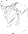
- FIG. 19A illustrates a cross-sectional view of the assembly shown in FIG. 6A having additional components according to one or more implementations of the present disclosure
- FIG. 19B illustrates a perspective detailed view of the assembly shown in FIG. 19A ;
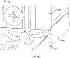
- FIG. 19C illustrates a perspective detailed view of the assembly shown in FIG. 6A having additional components according to one or more implementations of the present disclosure
- FIG. 20A illustrates a perspective view of an assembly of components of an exemplary wall system according to one or more implementations of the present disclosure
- FIG. 20B illustrates a perspective view of an assembly of some of the components shown in FIG. 20A ;
- FIG. 21A illustrates a perspective view of an assembly of components of an exemplary wall system according to one or more implementations of the present disclosure
- FIG. 21B illustrates a perspective view of an assembly of some of the components shown in FIG. 21A ;
- FIG. 21C illustrates a perspective view of an assembly of some of the components shown in FIG. 21B ;
- FIG. 22A illustrates a perspective view of one of the wall systems shown in FIG. 5 ;
- FIG. 22B illustrates a cross-sectional view of the wall system shown in FIG. 22A ;
- FIG. 22C illustrates a cross-sectional detailed view of a portion of the wall system shown in FIG. 22A ;
- FIG. 22D illustrates a cross-sectional detailed view of another portion of the wall system shown in FIG. 22A ;
- FIG. 22E illustrates a cross-sectional detailed view of another portion of the wall system shown in FIG. 22A .
- the words “can” and “may” are used in a permissive sense (i.e., meaning having the potential to), rather than the mandatory sense (i.e., meaning must).
- the terms “including,” “having,” “involving,” “containing,” “characterized by,” variants thereof (e.g., “includes,” “has,” and “involves,” “contains,” etc.), and similar terms as used herein, including the claims, shall be inclusive and/or open-ended, shall have the same meaning as the word “comprising” and variants thereof (e.g., “comprise” and “comprises”), and do not exclude additional, un-recited elements or method steps, illustratively.
- Coupled is used to indicate either a direct connection between two components or, where appropriate, an indirect connection to one another through intervening or intermediate components.
- connection does not necessarily imply direct contact between the two or more elements.
- coupling, attaching, connecting, and/or joining can comprise placing, positioning, and/or disposing the components together or otherwise adjacent in some implementations.
- directional and/or arbitrary terms such as “top,” “bottom,” “left,” “right,” “up,” “down,” “upper,” “lower,” “inner,” “outer,” “internal,” “external,” “interior,” “exterior,” “proximal,” “distal” and the like can be used solely to indicate relative directions and/or orientations and may not be otherwise intended to limit the scope of the disclosure, including the specification, invention, and/or claims.
- an appended letter can be used to designate an alternative design, structure, function, implementation, and/or embodiment of an element or feature without an appended letter.
- multiple instances of an element and/or sub-elements of a parent element may each include separate letters appended to the element number.
- the element label may be used without an appended letter to generally refer to instances of the element or any one of the alternative elements.
- Element labels including an appended letter can be used to refer to a specific instance of the element or to distinguish or draw attention to multiple uses of the element.
- disclosure of an illustrative measurement or distance less than or equal to about 10 units or between 0 and 10 units includes, illustratively, a specific disclosure of: (i) a measurement of 9 units, 5 units, 1 units, or any other value between 0 and 10 units, including 0 units and/or 10 units; and/or (ii) a measurement between 9 units and 1 units, between 8 units and 2 units, between 6 units and 4 units, and/or any other range of values between 0 and 10 units.
- various implementations of the present disclosure include a reconfigurable modular wall system having a plurality of reconfigurable modules, components, and/or design elements configured for interchangeable attachment one to another.
- implementations include a reconfigurable modular wall system having different connection details for common connection of adjacent sections.
- Certain implementations include differently shaped connection details or components and/or connection interface components (e.g., at a common interface).
- certain implementations include a plurality of different connection components respectively having one or more common, universal, and/or compatible connection interfaces and/or connection interface elements or members.
- Such connection components can allow a user to select a desired module or display element without regard to compatibility concerns as each module and/or connection component(s) thereof are formed, extruded, and/or manufactured so as to be compatible with any other module and/or connection component.
- Certain implementations can allow a user to reconfigure, reorient, rearrange, and/or replace one or more modules of a wall system without laborious alterations such as, for example: (1) redesigning the entire wall system; (2) changing, altering, and/or swapping connection components; (3) disassembling the entire wall and/or large (sub)section(s) thereof; and/or (4) requiring additional adapters, components, and/or compatibility elements to ensure proper alignment and/or attachment of the modules.
- some implementations include a “checker-board” or other style modular wall comprising a plurality of vertically and horizontally arranged modules, wherein any two modules, regardless of position on the checker-board or other design, can be swapped, rearranged, reoriented, or otherwise reconfigured without one or more of the aforementioned or other alterations or limitations.
- implementations can allow for additional modules to be added to the wall system (e.g., in a vertical and/or horizontal direction) to increase the height or width of the wall system without the requirement of one or more of the aforementioned or other alterations.
- implementations may allow for one or more modules to be removed from a wall system (e.g., in a vertical and/or horizontal direction) to decrease the height or width of the wall system without the requirement of one or more of the aforementioned or other alterations or limitations.
- implementations of the present disclosure can provide a universally compatible, reconfigurable modular wall system that does not require a pre-designed frame to be constructed prior to assembly of the wall and/or does not require a redesigned frame or subunit in order to change, alter, or otherwise reconfigure the wall or a portion thereof.
- this universal compatibility can permit the removal, addition, replacement, etc. of any wall module or unit with another module or unit without necessarily replacing one or more of the connection components associated with adjacent module(s) or unit(s).
- the intermediate glass wall module in a solid wall—glass wall—solid wall configuration or relationship can be replaced with a solid wall module to form a solid wall—solid wall—solid wall configuration or relationship without changing or replacing one or more of the connection components associated with the peripheral solid wall modules.
- the connection components associated with the peripheral solid wall modules are universally compatible with the connection components associated with the replaced glass wall module, as well as the replacing solid wall module.
- Implementations of the present disclosure can also include providing, applying, attaching, inserting, and/or otherwise implementing a common, universal, or multi-compatible connection interface component for securing a plurality of connection components together in a desired configuration, orientation, and/or arrangement.
- a universal connection interface component having a substantially X-shaped, Y-shaped, V-shaped, U-shaped, T-shaped, I-shaped, H-shaped, or other cross-section can be configured to secure two connection components together at an interface.
- the connection interface component can be inserted, slid, clipped, snapped, or otherwise positioned into one or more aligned, corresponding, and/or compatible attachment interfaces and/or channels in or of the connection component(s) and/or formed at the interface therebetween.
- each connection component can include one, two, or more attachment interface channels extending longitudinally at least partially between one end of the connection component and another and/or opposite end of the connection component.
- aligning such attachment interface channels in two or more connection components and/or positioning two or more connection components such that corresponding attachment interface channels are aligned can form a joint and/or shared channel in which a connection interface component can be inserted or otherwise positioned to reversibly and/or selectively secure the connection components together.
- Reconfiguration of and/or methods of reconfiguring a modular wall system can, therefore, comprise, involve, and/or include: (1) disengaging (e.g., slidedly or otherwise removing) one or more connection interface components from the corresponding attachment interface channels of the connection component(s) (and/or joint or shared channel formed thereby) to release, disconnect, detach, unfasten, or otherwise enable movement of one or more modules from the wall system; (2) removing, reorienting, replacing, and/or reorganizing one or more unsecured modules; (3) aligning corresponding attachment interface channels of the connection component(s) of adjacent modules (to form a joint or shared channel); and/or (4) re-engaging (e.g., slidedly or otherwise positioning) one or more connection interface components into the corresponding attachment interface channels of the connection component(s) (and/or joint or shared channel formed thereby) to secure, attach, connect, or otherwise assemble one or more modules to the wall system.
- disengaging e.g., slidedly or otherwise removing
- FIG. 1 illustrates a perspective view of an exemplary system according to one or more implementations of the present disclosure. More specifically, FIG. 1 illustrates a reconfigurable wall system 100 that includes a plurality of wall modules 102 arranged and/or coordinated in relation to one to another. For instance, a first module 102 a can be positioned (vertically) above or atop a second module 102 b within wall system 100 . Similarly, a third module 102 c can be positioned (horizontally) beside or next to the second module 102 b.
- modules 102 can be about 30.5 cm tall and about 30.5 cm wide. However, modules 102 can be any suitable size. For instance, modules 102 can be greater than, less than, up to, between, equal to, or about 10 cm, 20 cm, 25 cm, 35 cm, 45 cm, 60 cm, or more in length and/or width. Modules 102 can also have a standard thickness greater than, less than, up to, between, equal to, or about 1 cm, 2.5 cm, 5 cm, 7.5 cm, 10 cm, 12.5 cm, 15 cm, 18 cm, 20 cm, 22 cm, 25 cm, 28 cm, 30 cm, or more. Other standard sizes, measurements, and/or standards can also or alternatively be applied and/or adhered to in some implementations.
- each module 102 is substantially similar and/or identical in size, shape, and/or dimension(s).
- modules 102 can comprise different sizes, shapes, and/or dimensions.
- a first module 102 can be the size and/or shape of two smaller modules placed adjacent and/or connected to one another.
- Modules 102 can comprise and/or be a square, rectangle, and/or any other suitable (geometric or other) shape.
- a wall system 100 can be oriented in any suitable orientation, including diagonal, vertical or substantially vertical, and/or horizontal or substantially horizontal, wherein the term “substantially” indicates allowable, acceptable, or other deviation(s) from a perfect or other precise orientation.
- a substantially vertical orientation can account for small imperfections or errors in the assembly, construction, and/or formation of an upright divider or other wall system 100 , including assembling, mounting, constructing, or otherwise assembling the wall system 100 .
- “substantially” can imply less than 10%, less than 1%, less than 0.1%, or less than 0.01% variability or error relative to a perfect or precise orientation.
- a 1% error in vertical orientations i.e., a 3.6°, 1.8°, or 0.9° deviation
- diagonal orientations comprise those orientations that are neither vertical nor substantially vertical, nor horizontal nor substantially horizontal.
- the plurality of wall modules 102 can be arrangeable and/or re-arrangeable into a plurality of configurations resulting in a wall 100 or other barrier, divide, structure or structural component.
- the relative positions of wall modules 102 b and 102 c can be switched to allow for versatility in aesthetic or other design properties.
- the design and/or components of reconfigurable wall system 100 can allow for any module 102 to be placed, positioned, secured, and/or arranged in any position, orientation, and/or configuration available within system 100 .
- a first module 102 can be interchangeable, re-arrangeable, and/or replaceable by or with any other module 102 .
- modules 102 can be shuffled, organized, ordered, and/or arranged in a plurality of vertical and/or horizontal relationships. In at least one implementation, such rearrangement can be made without disassembling the entire wall system 100 and/or certain component(s) thereof. For instance, the vertical relationship between two vertically adjacent modules 102 can be rearranged without changing, disassembling, or otherwise affecting the assembly of modules 102 horizontally or vertically adjacent thereto. For instance, as discussed in further detail below, a module 102 disposed in any position within system 100 can be exchanged for another module 102 without also exchanging one or more of the connection components associated with module(s) 102 adjacent to the position of the exchanged module 102 .
- modules 102 can be arranged, organized, and/or configured into subunits 112 of the reconfigurable wall system 100 .
- vertical subunit 112 a can include four modules 102 configured and/or arranged in a vertical relationship.
- subunits 112 and/or modules 102 thereof can comprise and/or be arranged horizontally, diagonally, and/or in any other suitable orientation, shape and/or design configuration.
- subunits 112 can include 1, 2, 3, 4, 5, 6, 7, 8, or more modules 102 arranged in any suitable orientation or relationship.
- subunit 112 can comprise two modules 102 disposed vertically or horizontally (side-by-side).
- subunit 112 can comprise two upper modules 102 disposed side-by-side and connected to two lower modules 102 disposed side-by-side (e.g., creating a 2 ⁇ 2 modular subunit 112 ).
- each module 102 of a subunit 112 can be connected and/or attached to another module 102 of the subunit 112 via one or more connection components 104 .
- the reconfigurable wall system 100 can comprise a plurality of connection components 104 .
- each module 102 can comprise at least one upper and/or lower connection component 104 spaced apart according to the desired size or dimension of the module 102 .
- An illustrative connection component 104 can be designed to connect, attach, and/or mate with another, adjacent connection component 104 of the wall system 100 or a subunit 112 thereof.
- connection components 104 can be designed to connect, attach, and/or mate with (any other) adjacent connection component 104 (regardless of configuration, design, or structural features). Thus, connection components 104 can be universally compatible in some implementations.
- connection components 104 may allow for one or more of the modules 102 to be selectively added or removed from the wall system 100 to adjust the height of the wall 100 .
- connection components 104 may allow for one or more of the modules 102 in the middle of the wall 100 to be removed from the wall 100 without disassembling the surrounding portions of the wall 100 in order to replace the middle module(s) 102 or to adjust the height or width of the wall 100 .
- the height of the wall can be altered by adding or removing modules from interior, central, and/or middle (e.g., non-edge) positions, as opposed to outer, exterior, and/or edge-positioned modules.
- the width and/or length of wall system 100 can be similarly altered and/or adjusted.
- modules 102 can be about 30.5 cm tall and about 30.5 cm wide.
- subunit(s) 112 can be about 30.5 cm wide and about 1.22 meters tall.
- subunits 112 can vary widely from one implementation to another. For instance, subunit(s) 112 can be greater than, less than, up to, between, equal to, or about 10 cm, 20 cm, 25 cm, 35 cm, 45 cm, 60 cm, or more and/or any multiple thereof in length and/or width.
- Subunits 112 can also have a standard thickness greater than, less than, between, equal to, or about 1 cm, 2.5 cm, 5 cm, 7.5 cm, 10 cm, 12.5 cm, 15 cm, 18 cm, 20 cm, 22 cm, 25 cm, 28 cm, 30 cm, or more. Other standard sizes, measurements, and/or standards can also or alternatively be applied and/or adhered to in some implementations.
- each subunit 112 is substantially similar and/or identical in size, shape, and/or dimension(s).
- subunits 112 can comprise different sizes, shapes, and/or dimensions.
- a first subunit 112 can be the size and/or shape of two smaller modules placed adjacent and/or connected to one another.
- Subunits 112 can also comprise and/or be a square, rectangle, and/or any other suitable (geometric or other) shape.
- Connection component(s) 104 can comprise an elongated, structurally rigid or semi-rigid component substantially similar in length to the edge length of module 102 . Accordingly, connection component(s) 104 can also comprise any suitable size, shape, and/or other measurement or feature suitable to implementations thereof. For instance, connection component 104 can be greater than, less than, up to, between, equal to, or about 10 cm, 20 cm, 25 cm, 35 cm, 45 cm, 60 cm, 100 cm, 120 cm, 122 cm, or more in longitudinal length.
- connection component(s) 104 can have a height and/or thickness of greater than, less than, up to, between, equal to, or about 1 cm, 2.5 cm, 5 cm, 7.5 cm, 10 cm, 12.5 cm, 15 cm, 18 cm, 20 cm, 22 cm, 25 cm, 28 cm, 30 cm, or more in a first and/or second direction.
- connection component(s) 104 can be approximately 2 cm in a first (e.g., vertical) direction and/or approximately 10 cm in a second (e.g., horizontal) direction.
- Other connection component(s) 104 can be oppositely and/or otherwise configured.
- Connection component(s) 104 can comprise a rigid or semi-rigid, resilient material.
- connection component 104 and/or other components of system 100
- connection component 104 can comprise aluminum, steel, thermoplastic (e.g., reinforced thermoplastic).
- connection component 104 and/or other components of system 100
- connection component 104 can comprise an extruded, die-cast, injection-molded, milled, manufactured, fabricated or otherwise formed structural component.
- a manufacturer can fabricate, for instance, an aluminum extrusion that has any desired profile, which can create attributes, functionality, utility, and structural properties unique to each connection component 104 .
- each connection component 104 can be fabricated so as to be universally connectable to and/or compatible with any other connection component 104 .
- Other materials can also be used to form connection component 104 without departing from the scope of this disclosure.
- connection component 104 can comprise wood, stone, or any other natural or synthetic material suitable for use therein.
- Modules 102 can also include and/or be clad with one or more tiles 106 , such as a (solid) wall panel, glass pane, functional component, and/or display member.
- Tiles 106 can comprise and/or be made of wood, plastic, metal, fabric, textile, fiber, fiberglass, plaster, drywall, glass, resin, and/or other suitable materials without departing from the scope of this disclosure.
- a tile can comprise a plurality of such materials.
- a plurality of different types of tiles can be arranged in a desired fashion to achieve a desired aesthetic or other purpose.
- reconfigurable wall system 100 and/or subunit(s) 112 thereof can include a plurality of modules 102 respectively having a combination of glass and wall tiles 106 arranged such that a consistent, random, alternating, and/or patterned (regular or irregular) configuration is displayed on a viewing surface or face thereof.
- the modules 102 of wall system 100 have been configured such that various arrangements of adjacent glass tiles 106 a and wall tiles 106 b can be observed.
- Glass tiles 106 a and/or wall tiles 106 b can be translucent, transparent, or opaque in various implementations. Accordingly, a variety of functional and aesthetic combinations can be available by arranging a plurality of modules 102 in various relationships.
- tile 106 can comprise and/or include a functional component or cassette configured to provide additional utility to the wall system 100 .
- exemplary functional components include but are not limited to video monitors, audio speakers, shelves, mounting elements, control panels, access ports, outlets, and other utility-providing members.
- Functional components can also provide (additional) aesthetic properties and/or qualities without departing from the scope of this disclosure.
- tile 106 can comprise artwork or a design feature having a particular color, pattern, texture, etc. thereon.
- tile 106 can comprise a (picture) frame and/or matting configured to receive an insert.
- a functional component can be at least partially housed within, mounted onto, attached to, or otherwise received by at least a portion of tile 106 and/or module 102 in some implementations.
- a functional component e.g., video monitor
- the functional component can be associated with a glass tile 106 a such that the functional component can be viewed through the glass tile 106 a .
- the functional component can be received by a wall tile 106 b .
- the functional component can be mounted, attached, or connected to, or otherwise associated with the exterior surface of a solid or other wall tile 106 b.
- the functional component can also (or alternatively) be placed and/or secured within an opening, aperture, void, hollow, recess, groove, channel, or other area or region of the tile 106 configured to receive the functional component therein.
- a wall tile 106 b can comprise an opening or recess therein or area into which the functional component can be placed, mounted, and/or secured such that the functional component can be displayed and/or accessible on or within wall tile 106 b of module 102 c .
- a functional component can, in certain implementations, replace, provide, and/or behave as a tile 106 .
- the functional component itself, or component(s) thereof can be attached directly or indirectly to module 102 , wall system 100 , and/or component(s) thereof (e.g., by fitting such functional component with one or more connection component(s) 104 ).
- a tile 106 can be mounted, secured, and/or attached to an outer edge or component of a module 102 and/or connection component(s) 104 thereof.
- tiles 106 can be mounted, secured, and/or attached to both or opposing outer edges or components of a module 102 and/or connection component(s) 104 thereof.
- tiles 106 can be mounted, secured, and/or attached to both or opposing outer terminal edges of opposing connection components 104 .
- tiles 106 can be mounted, secured, and/or attached to both or opposing outer sides of a single connection component 104 .
- one or more tiles 106 can be mounted, secured, and/or attached to one or more inner or outer components and/or within one or more inner or outer mounting channels and/or tile receiving elements of a module 102 and/or connection component(s) 104 thereof.
- a glass tile 106 a can be mounted within respective inner channels of upper and/or lower connection components 104 of (each) module 102 a that includes a glass tile 106 a .
- Wall tiles 106 b can also be mounted within inner channels of upper and/or lower connection components 104 .
- the inner and/or outer channel(s) can be positioned (centrally or peripherally) along connection component 104 .
- a wall tile 106 b can be mounted to the respective outer edges of upper and/or lower connection components 104 of (each) module 102 c that includes a wall tile 106 b .
- Glass tiles 106 a can also be mounted to outer edges in some implementations.
- a module 102 can comprise a plurality of tiles 106 .
- module 102 c can comprise an outer or inner wall tile 106 b and an inner or outer glass tile 106 a (not shown).
- an outer glass tile 106 a can transparently or translucently cover an inner wall tile 106 b (or functional component thereof) to provide a desired aesthetic.
- a module can comprise opposing tiles 106 in certain implementations.
- a module can comprise opposing wall tiles 106 b , glass tiles 106 a , or any suitable combination thereof, including stacked layers or multiple tiles on one or more sides or portions of module 102 .
- Wall tiles 106 b and glass tiles 106 a can also comprise a texturing, finish, or other surface detail as necessary to create a desired aesthetic.
- reconfigurable wall system 100 or a module 102 or connection components 104 thereof configured to receive a wall tile 106 b includes one or more tile attachment elements (see e.g., tile attachment element 214 of FIGS. 2 and 3A ).
- Illustrative tile attachment elements can include one or more clips, fasteners, clamps, screws, and/or other attachment member capable of attaching a wall tile 106 b to the connection component 104 .
- Glass tiles 106 a can also be attached to respective connection components 104 by means of one or more tile attachment elements.
- Tile attachment elements can also include one or more channel inserts or other channel-associated attachment members configured to receive one or more tiles 106 and/or to secure one or more tiles 106 within one or more channels.
- Reconfigurable wall system 100 can also include one or more frame elements 108 .
- frame elements 108 are configured to provide support, structure, connection, or other attribute(s) to the wall system 100 and/or modules 102 or multi-module subunits 112 thereof.
- a first frame element 108 a can be configured to provide internal structure, support, and/or rigidity to the wall system 100 and/or module(s) 102 or subunit(s) 112 thereof and/or to connect adjacent modular subunits 112 , such as subunits 112 a and 112 b .
- One or more additional frame elements 108 such as frame elements 108 b and 108 c , can be configured to surround, support, and/or define the outer perimeter of the wall system 100 and/or module(s) or subunit(s) thereof.
- reconfigurable wall system 100 includes at least one vertical frame element 108 a and/or at least one horizontal frame element 108 c .
- Vertical frame element(s) 108 a can divide, separate, support, and/or provide structure to or form one or more subunits 112 and/or module(s) 102 thereof.
- vertical frame element(s) 108 a can span the height of wall system 100 and/or provide separation and/or support between subunits 112 a and 112 b .
- Vertical frame element(s) 108 b can also or alternatively provide an end cap for reconfigurable wall system 100 or a subunit 108 and/or modules 102 thereof.
- one or more modules 102 can include at least one vertical frame element 108 .
- one or more modules 102 can include a first vertical frame element 108 a disposed on a first side thereof and a second vertical frame element 108 b disposed on a second side thereof.
- First and/or second vertical frame elements 108 can extend the height of module 102 in some implementations.
- Module 102 can also include an upper connection component 104 and a lower connection component 104 .
- module 102 can comprise a box-frame and/or structurally-independent unit configured to be connected and/or attached to one or more adjacent modules 102 (e.g., without any intervening frame component).
- a vertical frame element 108 can be disposed between subunits 112 and/or modules 102 (including optional vertical frame element(s) 108 thereof).
- subunit 112 can include a plurality of vertically arranged modules 102 .
- Each module 102 can include an upper connection component 104 and/or a lower connection component 104 .
- a lower connection component 104 of a first, upper module 102 a can be connected with and/or to an upper connection component 104 of a second, lower module 102 b.
- Adjacent connection components 104 can be selectively and/or reversibly secured one to another by means of one or more connection interface components (see e.g., connection interface component 726 of FIGS. 6C, 6D, and 7 ).
- connection interface components can include or otherwise comprise an elongated and/or extruded attachment mechanism or member.
- a connection interface component fits securely within respective channels (see e.g., channel 621 of FIG. 6C ) of adjacent connection components 104 such that the connection components 104 are held, secured, attached, connected, and/or mounted to each other.
- frame element 108 can comprise or be a connection component 104 .
- vertical frame component 108 a and/or 108 b can comprise vertically-oriented connection component(s) 104 , having one or more attributes thereof (described above).
- frame elements 108 can be adapted for universal compatibility.
- frame elements 108 can be adapted or configured with one or more compatible attachment interfaces and/or channels.
- frame elements 108 can be adapted or configured to receive one or more connection interface components (e.g., for securing adjacent modules 102 or frame elements 108 thereof).
- a reconfigurable wall system 100 includes two modules 102 placed adjacent and connected to one another via one or more connection components 104 .
- a first module 102 which includes at least one tile having an upper connection component 104 and a lower connection component 104 attached thereto, can be connected to a second module 102 comprising at least one tile 106 having an upper connection component 104 and a lower connection component 104 attached thereto.
- the connected first and second modules 102 can be supported on one or more sides by at least one frame element 108 .
- Frame element(s) 108 can surround the connected first and second modules 102 entirely or partially, or otherwise connect thereto.
- each module 102 can comprise opposing vertical frame elements 108 connected to the at least one tile 106 .
- a module 102 can comprise a variety of configurations.
- a module 102 can include at least one tile 106 clad between upper and lower connection components 104 .
- modules 102 can be stacked atop one another in a vertical relationship.
- a module 102 can include at least one tile 106 clad between left and right connection components 104 .
- modules 102 can be placed beside each other in a horizontal relationship.
- one or more frame elements 108 a can be disposed between adjacent modules in certain implementations.
- wall system 100 can comprise a plurality of modules 102 that are universally interchangeable in their vertical and/or horizontal position, orientation, and/or relationship.
- a module 102 can comprise an arrangement of connection components 104 with or without a tile attached thereto.
- wall system 100 can comprise a frame 200 .
- Frame 200 can comprise a plurality of modules 102 , each module comprising a connection component 104 , optionally attached (vertically) to one or more adjacent connection component 104 of an adjacent module 102 .
- each connection component 104 can be attached and/or secured (horizontally) to one or more connection components of one or more adjacent modules 102 (e.g., via one or more frame elements 108 ).
- connection and/or attachment of a plurality of connection components 104 forms a modular wall frame 200 .
- Each module 102 of frame 200 can comprise at least one of an upper connection component 104 and/or a lower connection component 104 .
- a module 102 can comprise two connection components 104 separated by a distance, in certain implementations.
- a module 102 can comprise upper and lower connection components 104 and opposing vertical frame elements 108 , forming an independent module adapted and/or configured for attachment (or to be attached) vertically and/or horizontally to adjacent module(s) 102 .
- a module 102 can comprise two connection components 104 attached at an interface.
- modular wall frame 200 comprises seven modular subunits 112 a through 112 g in a horizontally adjacent relationship, each of which comprises four modules 102 in a vertically adjacent relationship.
- wall system 100 can comprises seven modular subunits 112 a through 112 g in a horizontally adjacent relationship, each of which comprises four modules 102 in a vertically adjacent relationship.
- the inner boundary of each subunit 112 can be defined by one or more vertical frame elements 108 a extending between upper and lower ends or portions thereof.
- frame end element 108 b can define the outer (left side) edge of modular subunit 112 a and, therefore, modular wall frame 200 and/or wall system 100 .
- a similar frame end element 108 can define the outer (right side) edge of modular subunit 112 g and, therefore, modular wall frame 200 and/or wall system 100 .
- an upper and/or ceiling frame element 108 c can define the upper edge of one or more modules 102 , subunits 112 , and/or modular wall frame 200 .
- a similar lower, floor, and/or sub-floor frame element 108 can define the lower edge of one or more modules 102 , subunits 112 , and/or modular wall frame 200 .
- modular wall frame 200 can adopt and/or comprise other configurations, including number, orientation, and arrangement of modules and/or subunits without departing from the scope of the disclosure.
- each module 102 can include one or more (e.g., opposing) frame elements 108 .
- inner frame element 108 a , outer frame end element 108 b , upper frame element 108 c , and/or lower frame element 108 d of frame 200 can comprise a plurality of frame elements 108 (e.g., at least one for each module 102 ).
- wall system 100 and/or frame 200 thereof can comprise a plurality of modular frame elements 108 (e.g., for each module 102 ) and can also include one or more inner, outer, upper, and/or lower frame elements 108 (e.g., for each subunit 112 , frame 200 , and/or wall system 100 ).
- module 102 can comprise one or more connection components 104 and/or one or more frame elements 108 (e.g., opposing upper and lower horizontal connection components 104 and opposing left and right vertical frame elements 108 ),
- subunit 112 can comprise one or more (e.g., a plurality of) modules 102 , optionally having one or more inner frame element 108 a , outer frame end element 108 b , upper frame element 108 c , and/or lower frame elements 108 d connected or attached thereto (e.g., surrounding subunit 112 ), and/or (iii) frame 200 (or wall system 100 ) can comprise one or more (e.g., a plurality of) modules 102 (and/or subunits 112 ), optionally having one or more inner frame element 108 a , outer frame end element 108 b , upper frame element 108 c , and/or lower frame elements 108 d connected or attached thereto (e.g.,
- FIG. 2 also illustrates tile attachment elements 214 for securing a tile 106 (not shown) to frame 200 or one or more connection components 104 and/or one or more frame elements 108 thereof.
- tile attachment elements 214 can be attached to tiles 106 (see FIG. 1 ) instead of being attached to frame 200 and/or one or more components thereof.
- tiles 106 can be configured for attachment to frame 200 and/or one or more components thereof by means of one or more tile attachment elements 214 connected thereto.
- FIG. 2 illustrates tile attachment elements 214 affixed to frame 200 (e.g., in order to demonstrate connection location(s) for tiles 106 ).
- a tile attachment element 214 a , 214 b can be configured for securing a glass, wall, and/or other tile, including a functional component, to an exterior region, element, and/or component of the wall system 100 or frame 200 thereof.
- interior mounting of such tiles can be achieved through the use of one or more tile attachment elements 214 c , 214 d .
- tile attachment elements 214 c and/or 214 d can include one or more channel inserts or other channel-associated attachment members configured to receive one or more tiles 106 and/or to secure one or more tiles 106 within one or more channels.
- FIG. 3A and 3B illustrate a (modular) subunit 112 comprising four connected modules 102 d , 102 e , 102 f , 102 g without (See FIG. 3A ) and with (See FIG. 3B ) tile(s) 106 attached to each of the modules 102 .
- FIG. 3A illustrates modules 102 d and 102 e (or connection components 104 thereof) are connected at interface 603 and form a channel 518 .
- FIG. 3B illustrates a first glass tile 106 a of module 102 d , a wall tile 106 c spanning modules 102 e and 102 f , and a second glass tile 106 a of module 102 g .
- tile 106 c can span a single module 102 that is the size of modules 102 e and 102 f , combined.
- a combined module 102 can similarly comprise an upper connection component 104 and a lower connection component 104 , and can optionally include one or more intermediate connection components 104 (e.g., for securing an intermediate portion of tile 106 c ).
- modular wall system 100 and/or subunit 112 thereof can comprise a plurality of modules 102 of identical, similar, and/or different sizes and/or shapes.
- subunit 112 can comprise 1, 2, 3, 4, or more modules 102 in some implementations.
- Subunit 112 can be or comprise a single (vertical) column of modules 102 , as illustrated in FIGS. 3A and 3B .
- subunit 112 can be or comprise a single (horizontal) row of modules 102 , or a plurality of adjacent rows and/or columns of modules 102 .
- subunit 112 can serve as, function as, be, and/or comprise a wall system 100 , module 102 , or other structural component.
- connection components 104 can be incorporated into modular wall system 100 , subunit 112 , and/or module 102 thereof.
- modules 102 and/or connection components 104 thereof can be universally compatible and/or comprise universally compatible interfaces.
- connection components 104 can be reordered, reorganized, and/or rearranged without requiring a complete overhaul of the system or replacement of otherwise suitable connection components 104 .
- modules 102 d and 102 e can have a channel 518 disposed therebetween.
- connection components 104 can form channel 518 at a connection interface.
- FIG. 3A further illustrates tile attachment elements 214 e and 214 f (attached to connection components 104 ) for securing a tile 106 c to (an exterior or outer portion of) connection components 104 , module 102 , and/or subunit 112 .
- Subunit 112 and/or modules 102 thereof can also comprise one or more frame elements 108 .
- each module 102 , subunit 112 , or wall system 100 can have (opposing) vertical frame elements 108 extending (vertically) between upper and lower connection components 104 .
- Vertical frame elements 108 can comprise inner frame element(s) 108 a and/or outer frame element(s) 108 b .
- Connection component 104 can have a first end (connected to inner frame element 108 a ) and a second end (connected to outer frame element 108 b ) and a length extending (longitudinally) therebetween.
- each module 102 , subunit 112 , or wall system 100 can have (opposing) horizontal frame elements 108 extending therefrom.
- Horizontal frame elements 108 can comprise upper frame element(s) 108 c and/or lower frame element(s) 108 d.
- FIG. 4 illustrates a modular wall 100 a comprising a frame 200 a and including a first subunit 112 a and a second subunit 112 b connected at an interface 416 via inner frame elements 108 a .
- frame element 108 c can be configured to substantially span the (top) length of the connected subunits 112 a , 112 b in certain implementations.
- frame element 108 b can be configured to substantially span the (side) height of the connected subunits 112 a , 112 b in certain implementations.
- Modular wall 100 a can comprise one or more channels 518 (disposed between modules 102 or connection components 104 thereof) and/or one or more channels 518 a (disposed between modules 102 or frame elements 108 thereof).
- two modules 102 can share a common connection component 104 or other structural member 404 without departing from the scope of this disclosure.
- Structural member 404 can also optionally include one or more channels 518 .
- Such a structural member 404 can be extruded, die-cast, injection-molded, milled, fabricated, manufactured, or otherwise formed as a single, unitary piece, element, or member that does not require a connection interface component (e.g., a connection interface component 726 , as illustrated in FIG.
- structural member 404 can divide and/or is disposed at an intermediate position of a single, double-sized module 102 e such that one, two, or more tiles 106 can be attached to the single module 102 e .
- Module 102 e can be the size of two or more smaller modules 102 in some implementations.
- a reconfigurable wall system 100 can comprise any suitable number of modules 102 , arranged in any suitable number of subunits 112 , including columns, rows, or other spatial, geometric, or other designs.
- subunit(s) 112 can be arranged as horizontal row(s) or other grouping arrangement(s) configured to simplify installation, removal, and/or reconfiguration of the system 100 .
- system 100 a can comprise a 2-by-4 subunit of another reconfigurable wall system 100 .
- modular subunits 112 a and 112 b can comprise a single subunit 112 in some implementations.
- Modules 102 can each comprise one or more tiles 106 .
- One or more tiles 106 can be centrally mounted about, between, and/or within one or more upper and/or lower connection components 104 .
- a transparent or translucent glass, resin, and/or other tile 106 a for example, can be centrally and/or peripherally mounted about, between, and/or within an upper connection component 104 and/or a lower connection component 104 .
- one or more wall tiles 106 b can be mounted, attached, and/or secured to an exterior surface and/or region of the connection component(s) 104 , module(s) 102 , subunit(s) 112 , and/or wall system 100 .
- Wall tiles 106 b can also be centrally and/or peripherally mounted, and glass tiles 106 a can be exteriorly mounted.
- a surface display element such as a wood veneer, vinyl or laminate overlay or coating, colored film, etc. (See e.g., surface finishing 107 of wall tile 106 b of FIG. 7 ).
- each module 102 comprises at least one glass or other tile 106 a and/or at least one solid or other wall tile 106 b .
- a module 102 comprising a plurality of glass or other tiles 106 a , a plurality of wall tiles 106 b , and/or a plurality of different tiles 106 is also contemplated herein.
- At least one module 102 can comprise a first tile 106 on a display side of the wall system 100 , and a second tile 106 on a non-display side of the wall system 100 .
- at least one module 102 can comprise a first tile 106 on a display side of the wall system 100 , and no tile 106 on a non-display side of the wall system 100 .
- Other implementations can include a wall system 100 having two display sides. In such implementations, it can be appropriate to provide one or more modules 102 having one or more glass tiles 106 a and/or first and/or second opposing wall tiles 106 b , each of which includes a transparent, translucent, finished, and/or opaque surface and/or a display element.
- Display elements can include any type, style, and/or manner of color, design, decoration, image, or other desirable display property; including substantially colorless display property.
- Tiles 106 can be positioned, for instance, on a non-display side of wall system 100 and can optionally comprise a non-display finish.
- Certain tiles 106 can be limited to the size, shape, dimensions, or other configurations of the module 102 to which they belong and/or are secured.
- each module 102 of the modular wall system 100 comprises a uniform or substantially uniform (or similar) size.
- modules 102 can be congruent in shape, size, and/or compatibility.
- Other tiles 106 can be designed and/or configured to adorn, attach to, or otherwise be associated with a plurality of modules 102 and/or extend beyond the size and/or shape of a module 102 .
- certain implementations can comprise a tile 106 c (See FIG. 3B ) spanning two or more modules 102 and/or subunits 112 of wall system 100 .
- glass tiles 106 a , display and/or wall tiles 106 b , and other tiles 106 can also be configured to span a plurality of modules 102 , including two, three, four, and so forth. Indeed, in at least one implementation, a tile 106 can span the entire length, height, and/or other dimension or measurement of a wall system 100 or subunit 112 thereof.
- module 102 can include a wall tile 106 b mounted to the exterior surface, edge, and/or region of one or more connection components 104 and/or frame elements 108 .
- tile(s) 106 can be configured to hide, substantially conceal, and/or reduce the visibility of at least part(s) of one or more modules 102 , connection components 104 , and/or frame elements 108 .
- Such exterior-mounted tiles 106 e.g., tiles 106 b
- Transparent and/or translucent glass, resin, or other tile(s) 106 a can also or alternatively be exterior-mounted.
- Some implementations can include one or more tiles 106 mounted in, within, or otherwise about the interior region of one or more connection components 104 and/or frame elements 108 .
- glass tile 106 a can be centrally or peripherally mounted between connection components 104 .
- a plurality of tiles 106 e.g., 106 a and/or 106 b , or a combination thereof
- tile(s) 106 can be configured to display, reveal, and/or permit the visibility of at least part(s) of one or more modules 102 , connection components 104 , and/or frame elements 108 .
- Such interior-mounted tiles 106 can comprise glass, resin, and/or any other material disclosed herein or otherwise suitable.
- Opaque tile(s) 106 e.g., tiles 106 b
- Channel 518 can be formed at the connection interface 603 between two connection components 104 and/or the interface 416 between two frame elements 108 (e.g., channel 518 a ).
- channel 518 can be exposed through the space between two installed tiles 106 . Accordingly, channel 518 can be accessible from the exterior surface of a wall system 100 .
- channel 518 can comprise a receiving channel, and thus, can be configured to house, secure, and/or receive a functional, display, and/or other object, component, member, or element.
- Such components can include, for example, one or more: cantilevers or object mounting elements; LED or other lighting elements (e.g., lighting strips), which can be powered by elements internal to the wall structure in some implementations; magnetic elements or strips; tackable elements, comprised of wood, cork, or other material, and which can be used to attach or affix other objects thereto; tubing or other conduit or channel material, component, or element configured to permit passage of matter therethrough; and any other functional component (including decorative components), whether known in the art or otherwise available.
- the one or more lighting elements may be used to provide one or more functions.
- the one or more lighting elements may be used to illuminate a space defined by the wall system 100 .
- the illumination can provide enough light in the space to allow occupant(s) to be able to see.
- the illumination may provide a guide or directions through the space (e.g., when the space is a hallway).
- the one or more lighting elements may also be used to provide aesthetics to the space defined by the wall system 100 . For instance, the color or level of lighting (e.g., dim, bright, etc.) provided by the one or more lighting elements may be altered or otherwise used to set or change the aesthetics of the space defined by the wall system 100 .
- the one or more lighting elements may be used for communication purposes.
- the one or more lighting elements may be used to identify the status of the space defined by the wall system 100 .
- the status of the space defined by the wall system 100 may include whether the space is occupied or available.
- the color of the one or more lighting elements may be changed to indicate the status of the space defined by the wall system 100 .
- the status of the space may be communicated by the lighting elements by having the lighting elements unlit or lit, or light with a specific color.
- the lighting elements in the channel 518 on the exterior and/or interior of the wall system 100 may be lit and/or lit with a specific color (e.g., red).
- a specific color e.g., red
- the lighting elements in the channel 518 on the exterior and/or interior of the wall system 100 may be unlit and/or lit with a specific color (e.g., green).
- the lighting elements may be used to communicate other messages. For instance, the lighting elements may be lit with a specific color (e.g., red) to indicate that there is an emergency.
- the one or more lighting elements may also be lit and/or unlit in certain patterns to communicate messages (e.g., emergency, occupied, available, etc.).
- the lighting element can comprise an LED or other message board or strip in certain implementations.
- the lighting element can display advertisements, instructions, directions, news, updates, text, etc.
- the lighting element can display arrows, characters, figures, or any other suitable images for a specific purpose or effect.
- the lighting element(s) within channel 518 can provide a variety of aesthetic, functional, informative, or other utilities. Additional uses will be apparent to those skilled in the art or by practice of the present disclosure.
- channel 518 can receive a gap-sealing or other functional component or member configured to cover, close, block, seal, or prevent fluid or other access to at least a portion of the channel 518 .
- Such a sealing member can prevent dust, water, debris, and/or other materials or substances from entering and/or being retained within channel 518 .
- functional components can provide, comply with, and/or adhere to building or other code or regulation.
- functional components can comply with and/or adhere to hospital or other healthcare or other facility rules, regulations, and/or building codes.
- a receiving channel 518 (as well as any other channel or channel member, etc. described and/or disclosed herein) can be configured to receive one or more functional components of any suitable nature or variety.
- channel and/or receiving channel 518 can also (or alternatively) comprise a cantilever or other channel configured to allow objects to be hung and/or supported therefrom.
- a cantilever channel 518 at the interface between two (e.g., upper and lower) modules 102 (and/or connection component(s) 104 or frame element(s) 108 thereof), or between tiles 106 of and/or attached to the same can allow for various accessories or mill work to be supported by a wall system 100 , 100 a (and/or subunit(s) 112 and/or module(s) 102 thereof) on the outside thereof at convenient locations that can be adjusted as needed.
- cantilever channel 518 can comprise a shared cantilever channel between two or more connection components 104 , modules 102 , subunits 112 , walls, and/or systems 100 , 100 a.
- Channel 518 can comprise an opening or gap into the channel portion or element of the channel 518 .
- the channel opening or gap can comprise any height, width, length, radius, diameter, circumference, perimeter, and/or other dimensional measurement suitable for implementations thereof.
- the opening or gap can be relatively small compared to the size of the module (e.g., a fraction of the size of the length, width, height, etc. of the module).
- the opening or gap can be designed to reduce visibility thereof. For instance, the opening or gap can be greater than, less than, up to, between, equal to, or about or approximately 9 mm, 7 mm, 4 mm, 3 mm, 2 mm, or 1 mm.
- the opening or gap can be designed and/or configured to allow a certain size, gauge, etc. cantilever to pass therethrough, enter therein, and/or access the cantilever channel 518 .
- openings or gaps can range in size from 1-100 mm or more, 10-100 cm or more, or 1-10 m or more without departing from the scope of this disclosure.
- wall systems 100 described herein can also or alternatively include relatively large structures, buildings, pods, modules, and/or components and are not limited to conventional size, interior walls or wall modules customarily found in office, commercial, and/or industrial space, or other divided spaces known in the art.
- Such structures and/or structural components can be configured and/or reconfigured according to systems and methods described herein.
- portable classroom pods, storage containers, emergency or disaster relief housing, etc. can comprise modules and/or subunits of a modular system of connected modules or pods in one or more planes and/or directions.
- modules 102 of a wall system 100 can comprise 3-dimensional rooms, voids, spaces, etc.
- Such modules can include walls comprising connection components 104 and/or frame elements 108 and can be universally compatible, such that assembly and/or reconfiguration of a variety of such modular structures are possible.
- connection components 104 and/or frame elements 108 can be universally compatible, such that assembly and/or reconfiguration of a variety of such modular structures are possible.
- Other applications and implementations for systems, methods, and apparatus described and/or disclosed herein will be apparent to those skilled in the art in light of the subject matter, disclosure, and/or descriptions found herein.
- Cantilever channel 518 can also be configured to support a substantial or other amount of weight without causing significant damage, disassembly, or other undesirable alteration to the wall system 100 and/or one or more subunits 112 , modules 102 , connection components 104 , and/or frame elements 108 .
- cantilever channel 518 and/or component(s), module(s), subunit(s), wall(s), and/or system(s) incorporating and/or implementing the same can be configured to support between 1 pound and 2000 pounds or more of gravitational, lateral, and/or other weight and/or torque (e.g., without structural failure, dissociation, and/or disassembly of the same).
- certain implementations can be configured to support at least 700 pounds or more of such weight or torque.
- a specific number of pounds per linear-, square-, or cubic-foot or other measurement can be supported thereby.
- certain implementations can be configured to support at least 700 pounds or more of such weight (or torque) per (or every) 48 inches, illustratively.
- wall system 100 can support desktops, work surfaces, appliances, shelves, and/or any other suitable and/or desirable objects using cantilever channel(s) 518 .
- cantilever channel 518 comprise a substantially continuous channel across the length, width, height, and/or other distance or measurement of one or more modules 102 and/or subunits 112 .
- at least one cantilever channel 518 runs the entire length of wall system 100 .
- each module can optionally form a separate channel 518 at an interface with an adjacent module 102 .
- a centrally-positioned module 102 can form an upper, lower, left side, and/or right side channel 518 at the interface(s) with adjacent module(s) 102 .
- FIG. 5 illustrates an arrangement of four modular wall systems 100 c , 100 d , 100 e , and 100 f , respectively.
- Each modular wall system 100 c , 100 d , 100 e , and 100 f comprises a unique arrangement of upper and lower modules 102 having various configurations or implementations of connection component(s) 104 , frame element(s) 108 , and/or tile(s) 106 .
- certain modules 102 include a central, channel-mounted glass tile 106 a .
- Other modules 102 include opposing, channel-mounted glass tiles 106 a .
- Some modules 102 include opposing, exterior-mounted wall tiles 106 b .
- Another module 102 is void of or does not include a tile.
- each modular wall system 100 c , 100 d , 100 e , and 100 f can comprise a horizontal channel 518 (at the connection interface between upper and lower modules 102 or connection components 104 thereof) and/or a vertical channel 518 a (at the connection interface between left and right modules 102 or frame elements 108 thereof).
- modules 102 can include additional connection components 104 in some implementations.
- one or more of the upper modules 102 of modular wall systems 100 c , 100 d , 100 e , and 100 f can have an upper connection component 104 (not shown) similar, identical, or different in configuration and/or design to lower connection component 104 .
- one or more of the lower modules 102 of modular wall systems 100 c , 100 d , 100 e , and 100 f can have a lower connection component 104 (not shown) similar, identical, or different in configuration and/or design to upper connection component 104 .
- modular wall systems 100 c , 100 d , 100 e , and 100 f , or one or more modules 102 thereof can include upper, lower, and/or outer side frame elements (not shown). Modules 102 can also be structurally supported by one or more splines 942 or other reinforcing members that can be attached to, between, and/or about one or more frame elements 108 .
- Connection components 104 and/or frame elements 108 can be specifically adapted for receiving tile(s) 106 and/or accommodating a specific configuration. For instance, certain connection components 104 and/or frame elements 108 can be configured to receive a single tile 106 . Other connection components 104 and/or frame elements 108 can be configured to receive a plurality of (e.g., a pair or opposing) tiles 106 . In addition, some connection components 104 and/or frame elements 108 can present or comprise a specific design feature or configuration. For instance, some connection components 104 and/or frame elements 108 can present or comprise a curvilinear, rectilinear, or some other design feature or configuration.
- each of the modules 102 illustrated in FIG. 5 can be universally and interchangeably compatible one with at least one other module 102 , in some implementations.
- each connection component 104 can comprise a common or universal interface such that the lower connection component 104 of each upper module 102 is compatible with the upper connection component 104 of each lower module 102 across modular wall systems 100 c , 100 d , 100 e , and 100 f .
- each frame element 108 can comprise a common or universal interface such that each module 102 is interchangeably horizontally positionable.
- each module 102 can be compatible with the frame element(s) 108 of each of the other modules 102 across modular wall systems 100 c , 100 d , 100 e , and 100 f . Accordingly, any of the upper modules 102 illustrated in FIG. 5 can be removed and replaced by another similarly or differently configured upper modules 102 and/or any of the lower modules 102 illustrated in FIG. 5 can be removed and replaced by another similarly or differently configured lower modules 102 .
- each of the modules 102 illustrated in FIG. 5 can be reoriented (or adapted for being reoriented) in place by removing the module 102 , changing the orientation thereof, and reinstalling or reattaching the module 102 in place (such that the left side of module 102 becomes the right side of module 102 when reattached or reinstalled).
- modules 102 can be reoriented such that the top of the module 102 becomes the bottom of the module 102 when reattached or reinstalled.
- FIGS. 6A-6D illustrate an assembly 300 of components of an exemplary system according to implementations of the present disclosure.
- assembly 300 can comprise an upper connection component 104 a having an elongated support member 631 a extending longitudinally between a first (terminal) end 632 and an opposing (terminal) second end 633 (not shown).
- Support member 631 a can have a substantially rigid or semi-rigid configuration in some implementations.
- upper connection component 104 a (or support member 631 a thereof) can have at least one tile (or panel) receiving member or element 605 .
- Tile receiving member or element 605 can comprise a channel that is recessed into (curved and/or curvilinear) upper surface 103 a of connection component 104 a .
- Tile receiving member or element 605 can extend longitudinally (at least partially) between first end 632 and second end 633 in some implementations.
- the channel can also or alternatively extend (upwardly) from the surface 103 a of connection component 104 a .
- tile receiving member or element 605 can be otherwise situated, positioned, and/or configured on and/or in connection component 104 a .
- tile receiving member or element 605 need not include a channel and/or need not be associated with upper surface 103 a in certain implementations.
- Assembly 300 further comprises lower connection components 104 b attached to opposite sides of upper connection component 104 a , and a wall panel 106 b attached to one of the lower connection components 104 b.
- tile receiving member or element 605 can be formed as a channel (recessed into support member 631 a and/or surface 103 a thereof) having one or more tile securing members 609 .
- tile receiving member or element 605 can have (opposing) tile securing members 609 a and/or 609 b .
- Tile securing members 609 can comprise protrusions extending into channel 605 .
- the protrusions can be substantially linear and/or include hook shaped and portion(s) in some implementations.
- assembly 300 can include one or more tile securing or attachment elements 606 (e.g., inserted at least partially into channel 605 ).
- tile securing element 606 can be inserted entirely into channel 605 such that one or more channel securing members 608 a thereof interact with, interlock with, associate with, and/or become (reversibly) secured to tile securing member(s) 609 and/or at least a portion of tile securing or attachment elements 606 contacts end wall 628 of channel 605 .
- tile securing element 606 can include one or more tile securing members 608 b adapted for retaining tile 106 a .
- tile securing member(s) 608 b can extend (inwardly) into a channel 607 of title securing element 606 . Accordingly, tile securing member(s) 608 b can retain tile 106 a within channel 607 and/or channel securing member(s) 608 a can retain tile securing element 606 within channel 605 .
- tile securing element 606 need not be inserted entirely into channel 605 (e.g., thereby contacting end wall 628 of channel 605 ) in some implementations.
- title securing element 606 can be inserted partially into channel 605 such that one or more channel securing members 608 a thereof interact with, interlock with, associate with, and/or become (reversibly) secured to tile securing member(s) 609 a of upper connection component 104 a .
- tile securing element 606 can still retain tile 106 a with channel 607 thereof by means of one or more tile securing members 608 b (e.g., extend (inwardly) into a channel 607 ).
- connection components 104 b can comprise one or more tile or panel attachment members 622 .
- Tile attachment member 622 can comprise a protrusion or other detail configured to receive and/or attach to a tile 106 .
- tile attachment members 622 can have one or more tile attachment elements 214 , such as, for example, a clip, a fastener, a gripper, a hanger, a clamp, a screw, and/or any other suitable attachment member or attachment means capable of attaching a wall tile 106 b to the connection component 104 b attached thereto.
- Glass tiles 106 a can also be attached to respective connection components 104 b by means of one or more tile attachment elements 214 connected to one or more tile attachment members 622 .
- each of lower connection components 104 b can be connected to upper connection component 104 a at an interface 603 .
- upper connection component 104 a can be attached to lower connection component 104 b at interface 603 , and vice versa.
- Connection components 104 e.g., 104 a , 104 b
- Upper connection component 104 a can also be attached to lower connection component 104 b at a second, similar, same, or different interface 603 .
- Connection components 104 can also form one or more cantilever or other channels 518 (e.g., at interface 603 ). Accordingly, assembly 300 can comprise one or more cantilever or other channels 518 .
- assembly 300 includes opposing first and second cantilever channels 518 (e.g., on opposite sides of assembly 300 or connection components 104 thereof).
- Cantilever channel 518 can comprise, be comprised of, and/or be formed from one or more channel walls and/or channel members 624 of connection component(s) 104 .
- upper connection component 104 a comprises a first cantilever channel member 624 a
- the lower connection component 104 b comprises a second cantilever channel member 624 b .
- the alignment and/or attachment of a plurality of connection components 104 at an interface 603 can form cantilever channel 518 from or of cantilever channel members 624 a , 624 b.
- the terms “align,” “alignment,” and the like refer to placing two or more objects, features, elements, members, components, etc. in and/or into a position configured to allow for a desired event and/or outcome, and do not necessarily require the congruent, exact, or other perfect matching of such objects in a single or plurality of planes.
- two objects can be aligned in separate planes by adjusting the position of one or more of said objects such that they are placed in proximity, interlock, cooperate, and/or correspond one to another.
- such objects can be placed in a distal configuration without departing from the scope of this disclosure when such distal configuration allows, permits, causes, promotes, and/or leads to a desired event and/or outcome.
- connection components 104 e.g., at or by means of alignment or formation of an attachment interface channel 620 , as discussed below
- properly aligned connection components 104 can have, comprise, display, and/or present a number of characteristics.
- properly aligned connection components 104 can respect and/or conform to interface 603 such that no part or portion of connection components 104 crosses the interface.
- opposing channel members 624 a and 624 b can be withdrawn or recessed relative to interface 603 .
- first channel members 624 a can be set back a first distance 625 a relative to interface 603 and/or second channel members 624 b can be set back a second distance 625 b relative to interface 603 .
- First distance 625 a and second distance 625 b can be (substantially) equal, similar, or different in various implementations.
- First distance 625 a , second distance 625 b , and/or the sum total distance thereof can be less than, greater than, up to, at least, equal to, between, or about 1 mm, 2 mm, 3 mm, 4 mm, 5 mm, 6 mm, 7 mm, 8 mm, 9 mm, 10 mm, 12 mm, 15 mm, 20 mm, or more in some implementations.
- such distances can be on the order of centimeters in certain implementations.
- Upper connection component 104 a can also comprise a (first) cantilever channel recess 908 a and/or lower connection component 104 b can comprise a (second) cantilever channel recess 908 b .
- Cantilever channel recesses 908 can be adapted to receive a portion of a cantilever or other insert therein. For instance, as illustrated in FIG. 6C , a terminal or tail end 906 of cantilever 905 can be secured into cantilever channel recess 908 when the cantilever 905 is properly inserted into cantilever channel 518 .
- Cantilever 905 can also include a body portion 909 .
- body portion 909 can be secured against and/or rest upon at least a portion of lower connection component 104 b (e.g., channel member 624 ) and/or tile 106 b .
- Cantilever 905 can also include an outer and/or functional end 910 .
- Functional end 910 can comprise a hook or other attachment mechanism for securing one or more items thereto.
- connection components 104 can also include one or more interface channels 621 .
- channel 621 can include one or more recessed portions 626 .
- two or more interface channels 621 can align and/or come together to form an attachment (or attachment interface) channel 620 .
- a first interface channel 621 can align with an attachment element and/or member (not shown) to form an attachment interface element and/or channel 620 .
- attachment interface channel 620 can comprise and/or be comprised of or formed from one or more interface channels 621 and/or attachment elements (not shown), or combination thereof.
- a plurality of such attachment elements can align and/or cooperate to form an attachment mechanism configured to secure at least a first connection component 104 to at least a second connection component 104 at an attachment interface 603 .
- a plurality of interface and/or connection interface elements and/or members can align and/or cooperate to provide and/or form an attachment mechanism configured to secure at least a first connection component 104 to at least a second connection component 104 at an attachment interface 603 .
- connection interface component 726 can be attached and/or connected to lower connection components 104 b (at interface 603 ) via a connection interface component 726 .
- connection interface component 726 can be received within attachment interface channel 620 (or interface channels 621 thereof) and thereby secure upper connection component 104 a to lower connection component 104 b .
- connection interface component 726 comprises a universal connection interface component having a substantially X-shaped cross-section. Suitable alternative configurations for connection interface component 726 will be apparent to those skilled in the art and can depend at least partially on the design of attachment elements or interface channels 621 .
- connection interface component 726 can be configured to secure two connection components 104 together at interface 603 .
- Connection interface component 726 can comprise one or more arms or channel engagement elements 728 configured to secure a plurality of connection components 104 together.
- one or more arms or channel engagement elements 728 can be adapted for insertion into one or more recessed portions 626 of channel 621 .
- Connection interface component 726 can comprise an X-shaped body having four arms or channel engagement elements 728 extending therefrom.
- connection interface component 726 can comprise other shapes and features or elements (e.g., a T-shaped body having three arms, a star-shaped body having five or more arms, an I-shaped body having two arms, etc.) without departing from the scope of this disclosure.
- connection interface component 726 and/or arms or channel engagement elements 728 can further comprise sub-arms and/or elements extending therefrom. Such features can enhance the effectiveness of connection interface component 726 and/or arms or channel engagement element 728 in some implementations.
- Connection interface component 726 and/or arms or channel engagement elements 728 can secure a plurality of connection components 104 together by aligning and securing together one or more channels 621 of the plurality of connection components 104 .
- connection interface component 726 can be inserted and/or otherwise positioned within attachment interface channel 620 , channel(s) 621 thereof, and/or recessed portion(s) 626 thereof.
- a first channel engagement element 728 (or portion thereof) of connection interface component 726 can engage a first interface channel 621 (or portion thereof) of lower connection component 104 b .
- lower connection component 104 b and/or first interface channels 621 thereof can include one or more (inwardly extending) interface component attachment members 623 adapted for receiving channel engagement element 728 .
- interface component attachment member(s) 623 can form and/or define recessed portion(s) 626 .
- interface component attachment members 623 can substantially prevent movement of connection interface component 726 in at least one direction.
- interface component attachment member 623 of lower connection component 104 b can substantially prevent movement of connection interface component 726 towards upper connection component 104 a .
- upper connection component 104 a can likewise include one or more interface component attachment members 623 . Accordingly, interface component attachment members 623 of upper and lower connection components 104 can substantially prevent separation of properly aligned connection components 104 from their connection at interface 603 .
- connection interface component 726 can engage a second interface channel 621 (or portion thereof) of upper connection component 104 a , thereby securing, coupling, connecting, attaching, and/or aligning connection components 104 (or channel(s) thereof).
- connection interface component 726 can be slideably insertable into and/or removable from the attachment interface channel 620 (or channel(s) 621 thereof).
- assembly 300 can be assembled by aligning connection components 104 at interface channels 621 to form an attachment interface channel 620 and inserting a connection interface component 726 therein.
- Connection interface component 726 can thereby ensure proper alignment of two or more connection components 104 at interface 603 .
- FIG. 7 illustrates an alternative assembly 300 a of components of an exemplary system according to one or more implementations of the present disclosure.
- opposing upper connection components 104 c are each attached to respective (opposing) lower connection components 104 b at an interface 603 via connection interface component 726 .
- One or more tiles 106 b can be attached or attachable to upper and/or lower connection component(s) 104 b , 104 c on one, both, or more sides of assembly 300 a (e.g., via tile attachment elements/members 214 , 622 ).
- a cantilever 905 can be provided for securing one or more objects to assembly 300 a .
- Cantilever 905 can be positioned within cantilever channel 518 such that an object can be supported therefrom.
- Cantilever 905 can include a foot or locking element 906 configured to fit securely within a slot or recessed channel 908 of connection component 104 c or channel 518 , such that cantilever 905 is selectively and/or reversibly retained within channel 518 .
- Connection interface components 726 can also be configured to secure and/or connect connection components 104 b , 104 c such that the connection components 104 b , 104 c remain attached, connected, and/or secured when a force or weight from the cantilever 905 is applied.
- cantilever 905 can induce torsion and/or other force(s) within channel 518 .
- Such a force can bias connection components 104 b , 104 c to separate and/or detach.
- Connection interface components 726 can, therefore, overcome or counter such force and retain connection components 104 b , 104 c in a secure, aligned, attached, and/or associated configuration.
- Cantilever 905 can have a variety of configurations, lengths, heights, and/or other characteristics. For instance, cantilever 905 can extend longitudinally between opposing (horizontal) ends of a connection component 104 . Accordingly, cantilever 905 can extend across a module 102 , subunit 112 , and/or wall system 100 of the present disclosure. As will be discussed in further detail below, in some implementations, cantilever 905 can extend latitudinally between opposing (vertical) ends of a frame element 108 . Cantilever 905 can also have a variety of shapes and/or designs, including shelves, platforms, hooks, and/or other design features as known in the art and described herein.
- cantilever 905 can, at least partially, contact and/or rest upon tile 106 b and/or be supported thereby.
- Tile 106 b can, therefore, be configured to at least partially support the weight and/or force applied by the cantilever 905 and/or object(s) attached thereto.
- FIGS. 8 and 9 illustrate connection components 104 c and 104 b , respectively, as illustrated in assembly 300 a of FIG. 7 .
- FIG. 8 illustrates a solid, uniform, unitary, seamless, and/or extruded connection component 104 c configured and/or oriented as an upper connection component 104 c , with channel 621 thereof oriented downward.
- Connection component 104 c can comprise an elongated support member 631 c extending longitudinally between a first (terminal) end 632 c and an opposing (terminal) second end 633 c .
- Support member 631 c can have a substantially rigid or semi-rigid configuration in some implementations.
- connection component 104 b configured and/or oriented as a lower connection component 104 b , with channel 621 thereof oriented upward.
- connection components 104 can be oriented in any direction without departing from the scope of this disclosure.
- Connection component 104 b can also comprise an elongated support member 631 b extending longitudinally between a first (terminal) end 632 b and an opposing (terminal) second end 633 b .
- Support member 631 b can have a substantially rigid or semi-rigid configuration in some implementations.
- Connection component(s) 104 can also be fabricated, manufactured, formed, extruded, and/or comprised of any suitable material, including aluminum, steel, and/or other types of metal and/or metal alloy, as well as any other suitable synthetic and/or natural material, or any suitable combination thereof.
- multi-component connection component(s) 104 are also contemplated herein.
- connection components 104 can be similar or identical in some or all features and/or elements thereof.
- the respective connection components 104 of FIGS. 8 and 9 have substantially similar configurations in certain features thereof. However, there are some differences between the respective connection components 104 of FIGS. 8 and 9 .
- the cantilever channel member 624 b of connection component 104 b can be configured to provide a “hooked” end or opening to cantilever channel 518
- the cantilever channel member 624 c can be configured to provide a “straight” end or opening to cantilever channel 518 .
- connection components 104 b and 104 c can comprise a straight protruding and/or arrowhead barbed tile attachment member 622 c
- connection component 104 b (or support member 631 b thereof) can also comprise an angled and round headed tile attachment or support member 622 b.
- connection components 104 can be inverted, interchanged, etc. However, in other implementations, connection components 104 are designated, configured, and/or designed to be assembled, attached, connected, and/or applied as an upper, lower, and/or other connection components 104 .
- connection component 104 c illustrated in FIG. 8 is configured for implementation as an upper connection component 104 c
- the connection component 104 b illustrated in FIG. 9 is configured for implementation as a lower connection component 104 b (e.g., as illustrated in FIG. 7 ).
- FIG. 10 illustrates an alternative assembly 300 b comprising opposing upper connection components 104 c attached to opposing sides of lower connection component 104 a .
- Assembly 300 b is configured to receive a lower, centrally-mounted tile 106 a in tile receiving member 605 (via tile securing or attachment member 606 mounted therein) and opposing upper, exterior-mounted tiles 106 b (via tile attachment members 622 , respectively, having a tile attachment element 214 connected thereto).
- certain implementations can include one or more connection components 104 configured to receive one or more tiles 106 in a central- and/or exterior-mounted configuration, oriented as upper and/or lower connection components 104 without departing from the scope of this disclosure.
- implementations of the present disclosure can relate to, include, and/or comprise interchangeable details, parts, and/or components designed and/or configured to allow versatility, configurability, and/or universality among such components.
- any such universally-configured connection or other component described and/or disclosed herein can be interchangeably attached and/or connected to any other such component (e.g., to form a module, subunit, frame, assembly, wall, and/or system as described herein or known in the art).
- the assembly 300 b of FIG. 10 is substantially similar to an inverted-version of assembly 300 of FIG. 6C .
- FIG. 11 illustrates another assembly 300 c of components of an exemplary system according to one or more implementations of the present disclosure.
- first and second center-mounting connection components 104 a can also be coupled together at an interface 603 via one or more connection interface components 726 secured within channel 620 (or channels 621 thereof) in certain implementations.
- FIG. 12 illustrates an alternatively-designed connection component 104 d according to one or more implementations of the present disclosure.
- a single, unitary, extruded, and/or manufactured connection component 104 d can be provided in the place of two of more connection components 104 connected at an interface via one or more connection interface components.
- connection component 104 d does not include a universal interface between upper and lower connection components 104 . Accordingly, removal and/or replacement of upper tile receiving element 605 a can occur simultaneously with removal and/or replacement of lower tile receiving element 605 b . However, upper tile receiving element 605 a may not be removable and/or replaceable without simultaneous removal and/or replacement of lower tile receiving element 605 b in such an implementation.
- connection components 104 can comprise various shapes, sizes, and/or configurations without departing from the scope of this disclosure.
- an illustrative connection component 104 e can comprise a rectilinear and/or squared-edge shape and center-mounting tile receiving element 605 .
- Tile receiving elements 605 can include a plurality of inwardly extending tile securing members 609 and/or an end wall 628 .
- Connection component 104 e can comprise a substantially flat and/or linear upper surface 103 b and substantially flat, opposing outer side surface 103 c .
- connection component(s) 104 can comprise rectilinear, straight, rounded, curved, angled, sharp, smooth, and/or various combinations of shapes, edges, and/or surfaces. It will be appreciated that while reference is made to upper surfaces, surfaces and other components or features can be inverted so as to change the orientation of the module 102 , connection component 104 , channel, or other component thereof (e.g., to face up or down or sideways).
- Connection component 104 e can also comprise one or more interface channels 621 (e.g., opposing interface channels 621 a , 621 b ).
- Interface channels 621 can include one or more interface component attachment members 623 (e.g., opposing interface component attachment members 623 a and 623 b ) and/or recessed portion(s) 626 (e.g., opposing recessed portions 626 a , 626 b ).
- Interface channel 621 can also include an end wall 627 in certain implementations.
- Connection component 104 e can also comprise one or more attachment openings 937 . Attachment openings 937 can be configured to receive one or more fasteners and/or other securing members (not shown). As discussed in further detail below, attachment openings 937 can be adapted for having one or more frame elements (see e.g., frame elements 108 a of FIG. 4 ) secured and/or reversibly secured thereto.
- FIG. 13B illustrates a connection component 104 f having a similar rectilinear and/or squared-edge profile and comprising a substantially flat and/or linear upper surface 103 b and substantially flat, opposing outer side surfaces 103 c .
- connection component 104 f comprises opposing tile receiving elements 605 c and 605 d .
- one or more tile receiving elements 605 e.g., opposing tile receiving elements 605 c and 605 d
- opposing tile receiving elements 605 c and 605 d can permit, allow, and/or be configured for mounting at least two tiles (peripherally) at opposite ends or edges of connection component 104 f.
- FIG. 13C illustrates a connection component 104 g having a shortened and/or narrowed rectilinear and/or squared-edge profile and comprising a substantially flat and/or linear upper surface 103 b and substantially flat, opposing outer side surfaces 103 d .
- Connection component 104 g also comprises a center-mounting, protruding tile receiving element 605 e .
- Protruding tile receiving elements 605 e can comprise opposing sidewalls 604 a and 604 b . Accordingly, tile receiving elements 605 e can extend above upper surface 103 b , as opposed to being recessed therein.
- a recessed tile receiving elements 605 e is also contemplated herein.
- Opposing outer side surfaces 103 d can be substantially shorter than opposing outer side surfaces 103 c.
- shorter outer side surfaces 103 d can provide an aesthetic advantage in certain implementations. For instance, shorter outer side surfaces 103 d can be less visible then longer outer side surfaces 103 c , from at least one vantage point. In addition, shorter outer side surfaces 103 d can accommodate the universally interchangeability of connection components 104 by allowing a tile 106 a (see FIG. 10 ) to be mounted within tile receiving elements 605 d while maintaining a similar and/or same distance from interface channel 621 (e.g., as compared to connection component 104 a , 104 e , etc.). In certain implementations, tile securing or attachment element 606 (see e.g., FIGS.
- a received end of a tile 106 a can be disposed in a similar and/or identical position relative to interface channel 621 in connection components 104 a , 104 e , 104 g , etc. (e.g., regardless of the configuration thereof).
- tile 106 a can be adjusted relative to end wall 628 of channel 605 in certain implementations.
- connection component 104 h can have extended, opposing outer side surfaces 103 e .
- connection component 104 h comprises a curved upper surface 103 a , substantially flat, extended, opposing outer side surface 103 e , and a recessed tile receiving element 605 f having extended sidewalls 604 .
- recessed tile receiving element 605 f comprises a channel 605 f that is substantially longer and/or deeper than that of tile receiving elements 605 a . Accordingly, a received end of a tile 106 a (see FIG.
- tiles 106 a can be mounted in similar and/or identical positions relative to interface channel 621 regardless of the exact configuration of connection component 104 .
- Connection component 104 h and/or tile receiving element 605 f thereof can also be configured to receive and/or accommodate a tile securing or attachment element 606 (not shown).
- connection component 104 i can be configured without a tile receiving element 605 .
- connection component 104 i comprises a curved upper surface 103 a , substantially flat, extended, opposing outer side surface 103 e , and no tile receiving element 605 (recessed into upper surface 103 a and/or extending therefrom).
- the foregoing or other connection components 104 can be designed and/or configured to be universally, completely, and/or partially compatible with any other connection component 104 .
- FIG. 14A illustrates additional, optional components of assembly 300 as previously described.
- FIG. 14A illustrates connection interface components 726 and 726 a securing together upper connection component 104 a and opposing lower connection components 104 b .
- first (opposing) connection interface components 726 are positioned within respective channels 620 on opposing sides of assembly 300 .
- connection interface component 726 a is securely (and centrally) attached to upper connection component 104 a via one or more fasteners 932 secured through one or more openings 931 in upper connection component 104 a .
- Connection interface component 726 a can comprise a body 933 and one or more tabs, arms, feet, protrusions, and/or other securing members 934 configured to secure together connection component 104 a and connection components 104 b .
- securing member 934 can engage a slot, recess, and/or channel 936 in one or more connection components 104 b when securing member 934 is placed in an engaged configuration, as illustrated in FIG. 14A .
- connection interface component 726 a can be at least partially rotatable around an axis of rotation 935 .
- FIG. 14B illustrates an alternative, disengaged configuration of the assembly 300 shown in FIG. 14A and, in particular, of connection interface component 726 a .
- rotation e.g., quarter-turn or 90 degree rotation
- connection interface component 726 a e.g., in a first direction around axis of rotation 935
- Securing member(s) 934 can thereby be removed from slots 936 by such an alteration in configuration, allowing for the dissociation of connection component 104 a and connection components 104 b in some implementations.
- Connection interface component 726 a can also be used to secure together adjacent frame elements 108 .
- connection interface component 726 a (e.g., in an opposite direction around axis of rotation 935 ) can re-engage securing member(s) 934 in slot(s) 936 and/or can engage a reversible locking mechanism to prevent unintentional rotation of connection interface component 726 a (e.g., in the first direction around axis of rotation 935 ).
- connection components 104 can comprise one or more attachment openings 937 .
- Attachment openings 937 can be configured to receive one or more fasteners and/or other securing members (not shown).
- attachment openings 937 can be adapted for having one or more frame elements 108 a secured and/or reversibly secured thereto. For instance, as illustrated in FIG.
- one or more inner frame elements 108 a can be attached, connected, and/or secured to the outer edge 629 of upper connection component 104 a and/or lower connection component 104 b by means of one or more fasteners 939 (e.g., to provide structure, stability, rigidity, and/or separation of or between modules, subunits, and/or components described herein.
- Frame elements 108 can also be attached to other component described herein.
- frame element(s) 108 can be shaped and/or formed to fit securely within the shape and/or form of the various connection components 104 and/or other components described herein.
- frame element(s) 108 can comprise one or more structural features 938 (e.g., channel, protrusion, and/or other element) configured to engage a portion, element, member, and/or structural feature of another component of assembly 300 , or any system, wall, subunit, module, and/or component thereof described and/or disclosed herein.
- Structural features 938 can be formed on outer surface 940 and/or inner surface 941 (see FIG. 15B ) of frame element 108 a . As illustrated in FIG.
- frame element 108 a can include a (central) tile receiving element 938 a (e.g., protruding and/or extending from inner surface 941 thereof).
- Tile receiving element 938 a can be configured to align with tile receiving member 605 of upper connection component 104 a . Accordingly, tile receiving element 938 a and tile receiving member 605 can operate to secure one or more tiles 106 a (not shown).
- assembly 300 can also include one or more components adapted for reinforcing frame elements 108 .
- a spline 942 or other reinforcing member can be attached to, between, and/or about one or more inner frame elements 108 a (e.g., within a recess and/or channel 940 a in outer surface 940 thereof) via one or more fastener(s) 939 .
- Spline 942 can provide support against lateral and/or other forces, and/or to hold modules, subunits, and/or components thereof together.
- insertion of spline 942 into adjacent and/or corresponding channels 940 a of upper and lower frame elements 108 a , respectively, can substantially secure and/or substantially immobilize upper and lower frame elements 108 a from moving horizontally relative to one another.
- assembly 300 can also include one or more attachment members 945 .
- attachment member 945 can fit securely between upper and lower frame elements 108 a (e.g., within a gap 950 therebetween) such that spline 942 can be secured to attachment members 945 and/or other components of assembly 300 using a single fastener 939 through a single opening 948 in spline 942 .
- attachment member 945 can fit securely within gap 950 between upper and lower frame elements 108 a .
- Spline 942 can then be aligned with frame elements 108 a such that opening 948 of spline 942 aligns with (threaded) opening 944 of attachment members 945 .
- Fastener 939 can then be inserted through opening 948 of spline 942 and (threadedly) received into (threaded) opening 944 of attachment members 945 , thereby securing spline 942 to assembly 300 by means of attachment members 945 .
- attachment of spline 942 to attachment members 945 can substantially secure and/or substantially immobilize spline 942 vertically.
- channels 940 a of upper and lower frame elements 108 a respectively, can substantially secure and/or substantially immobilize spline 942 in a substantially fixed horizontal position and attachment of spline 942 to attachment members 945 can substantially secure and/or substantially immobilize spline 942 in a substantially fixed vertical position. In this manner, spline 942 can be secured to upper and lower frame elements 108 a to prevent relative horizontal movement therebetween.
- minimizing the number of openings 948 in spline 942 can significantly increase and/or enhance the effectiveness and/or strength of spline 942 .
- minimizing the number of openings in frame element(s) 108 can significantly increase and/or enhance the effectiveness and/or strength thereof.
- attachment of spline 942 to frame element(s) 108 may not require any (additional) openings or other holes in frame element(s) 108 in some implementations.
- attachment members 945 can comprise a body portion 945 a and (opposing) arm(s) or other support member(s) 945 b . Such a configuration can substantially prevent lateral load (from adjacent assemblies, subunits, modules, etc.) from transferring to assembly 300 and/or frame elements 108 a thereof.
- FIG. 17 illustrates one or more additional, optional components of assembly 300 as previously described.
- assembly 300 includes a channel cap or other seal 946 inserted into and sealing off channel 518 from at least one side, edge, and/or opening.
- seal 946 closes the (horizontally-extending) gap between upper connection component 104 a and the lower connection component 104 b (and/or tile 106 b connected thereto).
- Seal 946 can include one or more feet 947 configured to engage one or more of connection components 104 and/or tiles 106 such that seal 946 is positioned, held, and/or secured within channel 518 .
- Seal 946 can also include a capping element 949 adapted for sealing and/or covering at least a portion of channel 518 .
- Seal 946 can further include one or more tail, foot, or other locking elements 948 configured to fit securely within slot or channel 908 of connection component 104 such that seal 946 is retained within channel 518 .
- Seal(s) 946 can be especially important and/or useful where a wall system is constructed and/or used in a hospital, healthcare, and/or other facility where dust, debris, and microbes retained within channel 518 is undesirable. Furthermore, as illustrated in FIG. 18 , seal 946 can be positioned within channel 518 and secured to upper and lower tiles 106 b in certain implementations. Seal(s) 946 can also be incorporated (vertically) between frame elements 108 of adjacent modules and/or subunits described herein. Thus, seal(s) 946 can be applicable and/or incorporated into any suitable assembly, subunit, wall, system, and/or other structure or configuration described and/or disclosed herein.
- frame element 108 can also be configured to receive seal 946 and/or locking element 948 thereof.
- frame element 108 a can have a slot, channel, or other receiving element 958 configured to accommodate and/or receive seal 946 and/or locking element 948 thereof.
- seal 946 can comprise an elongated, extruded, and/or extended cap-and-tail structure, member, and/or element configured to close and/or seal off at least a portion, segment, and/or section of channel 518 .
- seal 946 spans substantially the entire length, height, distance, and/or other measurement or parameter of channel 518 in a system, wall, subunit, module, and/or component.
- seal 946 can seal the gap or opening of channel 518 from a first end of a wall (system) 100 to a second and/or opposite end of the wall (system) 100 .
- seal 946 can extend between two adjacent modules 102 and/or subunits 112 in at least one implementation.
- seal 946 can be confined to a single module 102 and/or subunit 112 .
- some frame elements 108 a can lack a vertical slot, channel, or other receiving element. Accordingly, frame element 108 is not configured to receive seal 946 and/or locking element 948 thereof.
- FIG. 20A illustrates an assembly 300 e having two connection components 104 e connected and/or aligned (e.g., linearly and/or horizontally) at an interface 960 by means of one or more alignment elements 964 .
- Alignment element 964 can be configured to align two or more (laterally adjacent) connection components 104 in one or more directions and/or planes and can comprise one or more elements configured to align and/or secure connection components 104 together in a selective and/or reversible manner.
- Alignment element 964 (or one or more components thereof) can be disposed at least partially within interface channel 621 of connection component 104 e or a first portion 621 a thereof. Accordingly, connection components 104 e having two interface channels 621 can receive two alignment elements 964 . A plurality of alignment elements 964 can also be received into a single interface channel 621 in some implementations. It will be appreciated that a second portion 621 b of interface channel 621 can be configured to receive a connection interface component 726 (not shown) in certain implementations. In at least one implementation, alignment element 964 can be disposed in another suitable region, area, portion, and/or element of connection component(s) 104 e and/or assembly 300 e . In addition, as discussed in further detail below, alignment element 964 can be positioned or disposed within attachment interface channel(s) 620 of or formed by upper and lower connection components 104 (or respective interface channels 621 thereof).
- Alignment element 964 can be configured to properly align adjacent connection components 104 .
- alignment element 964 can comprise at least one translational member 972 .
- Translational member 972 can extend at least partially between adjacent connection components 104 e and/or provide a (direct or indirect) physical connection between other components of alignment element 964 attached or connected, respectively, to adjacent connection components 104 e .
- Alignment element 964 can also include one or more alignment element attachment members 973 (e.g., connected to opposing ends of translational member 972 ), one or more gripping and/or channel attachment members 978 (e.g., secured to or within interface channel 621 ; see FIG. 20A ), and/or one or more aligning members 975 disposed therebetween.
- channel attachment member 978 can include one or more gripping elements 979 .
- channel attachment member 978 includes a plurality of channel gripping teeth 979 .
- aligning member 975 can be or comprise a threaded, rotatable, tension or pulling rod (e.g., extending at least partially through channel attachment member 978 ).
- aligning member 975 includes one or more threads 976 disposed at a first end thereof and configured to be threadedly received within a corresponding threaded opening 974 of alignment element attachment member 973 .
- Aligning member 975 can also include an operating end 977 disposed on a second end thereof (e.g., opposite alignment element attachment members 973 and/or threads 976 ).
- Operating end 977 can include a tool receiving element 977 a in some implementations. In other implementations, operating end 977 can be hand-operated.
- opposing channel attachment members 978 can be secured within respective channels 621 of adjacent connection components 104 e .
- Respective aligning members 975 can be inserted through the secured channel attachment members 978 and threadedly received within threaded openings 974 of respective alignment element attachment members 973 .
- the alignment element attachment members 973 can be secured to opposing ends of translational member 972 . Accordingly, rotation of one or more of the aligning member 975 (e.g., about the axis of rotation thereof) can cause threads 976 to be received further into threaded opening 974 of alignment element attachment member 973 .
- FIG. 21A illustrates an assembly 300 f having four connection components 104 f attached, connected, and/or secured at a 90 degree, angled intersection or interface 960 a .
- connection components 104 can be attached, connected, and/or secured at any suitable angle.
- interface 960 a comprises a corner of a wall system 100 .
- connection components 104 can be configured, extruded, and/or mitered to accommodate a change in latitudinal direction of wall system 100 .
- a wall system 100 can require a directional change of less than, up to, greater than, equal to, between, or about 30 degrees, 45 degrees, 60 degrees, 90 degrees, 120 degrees, 135 degrees, and/or other angled (sharp or smooth/curved) configuration. Accordingly, connection components 104 and/or other components of wall system 100 can be configured to accommodate such angular and/or curved changes in direction.
- assembly 300 f of FIG. 21A includes four connection components 104 f arranged and secured together in a horizontally-adjacent and vertically-adjacent, angled configuration.
- connection interface component 726 can be positioned or disposed at least partially within attachment interface channel(s) 620 of or formed by at least one upper and at least one lower connection components 104 f (or respective interface channels 621 thereof), securing vertically-adjacent upper and lower connection components 104 f together.
- 21B and 21C further illustrate an exemplary mechanism of securing horizontally-adjacent (upper or lower) connection components 104 f together at an angle while still allowing, permitting, and/or accommodating connection interface component 726 to be positioned or disposed at least partially within attachment interface channel(s) 620 .
- FIG. 21B illustrates assembly 300 f having both upper connection components 104 f removed therefrom, exposing alignment elements 964 a and 964 b disposed within channel 621 of connection components 104 f .
- Alignment elements 964 a and 964 b can at least partially occupy a shared space within channel(s) 621 .
- Alignment elements 964 a and 964 b can be substantially similar (in structure and function) to alignment element 964 with one or more significant differences.
- alignment elements 964 a and 964 b can include angled translational members 972 a and 972 b (see FIG. 21C ), respectively.
- angled translational members 972 a and 972 b can be configured to fit within the angled transition between channel(s) 620 of assembly 300 f (or 621 of connection components 104 f thereof). Angled translational members 972 a can accommodate the angled alignment of connection components 104 f in a manner similar to the linear alignment described above in reference to FIG. 20A and alignment element 964 . For instance, similar to the mechanism of operation for alignment element 964 , operation of alignment elements 964 a and 964 b can pull or draw certain (alignment) components together, thereby drawing horizontally-adjacent connection components 104 f toward one another. Such pulling motion can continue until connection components 104 f are aligned in proper fashion (e.g., as illustrated in FIG. 21A ).
- translational member 972 b of alignment element 964 b can have an opening 971 disposed therein. Opening 971 can be configured to receive and/or accommodate one or more components of alignment element 964 a therein.
- alignment elements 964 a and 964 b can be at least partially superimposable within channel 620 , in at least one plane or dimension.
- alignment elements 964 a and 964 b each comprise channel attachment member 978 (oriented in opposite directions), alignment elements 964 a and 964 b can be disposed at least partially within (and secured to) respective channels 621 of opposing (upper and lower, respectively) connection components 104 f.
- one or more arms of translational member 972 b can be substantially longer than one or more arms of translational member 972 a .
- channel attachment member 978 of alignment element 964 b can be positioned, disposed, secured, and/or attached further from interface 960 a than channel attachment member 978 of alignment element 964 a in some implementations.
- alignment element attachment members 973 of alignment element 964 b can be positioned, disposed, secured, and/or attached further from interface 960 a than alignment element attachment members 973 of alignment element 964 a in some implementations.
- alignment elements 964 a and 964 b can be independently operated to fine-tune the attachment of connection components 104 f .
- alignment element 964 a can be placed and/or positioned at least partially within aligned channels 621 of horizontally-adjacent (lower) connection components 104 f .
- Alignment element 964 a can then be operated to secure together the horizontally-adjacent connection components 104 f .
- Alignment element 964 b can be placed and/or positioned (e.g., over-laid) atop alignment element 964 a .
- opening 971 can be disposed over or about one or more components (e.g., alignment element attachment members 973 , aligning member 975 , channel attachment member 978 , etc. see FIG. 20B ) of alignment element 964 a (at least partially within aligned channels 621 of horizontally-adjacent connection components 104 f ). Additional horizontally-adjacent (upper) connection components 104 f can be attached to positioned alignment element 964 b , which can then be operated to secure together the additional horizontally-adjacent (upper) connection components 104 f.
- alignment element 964 a at least partially within aligned channels 621 of horizontally-adjacent connection components 104 f .
- Additional horizontally-adjacent (upper) connection components 104 f can be attached to positioned alignment element 964 b , which can then be operated to secure together the additional horizontally-adjacent (upper) connection components 104 f.
- linear and/or corner-implementing and/or accommodating features and/or components described herein can also be implemented to adjoin corners of other components, including frame elements and/or tiles, etc.
- FIG. 22A illustrates a perspective view of a modular wall 100 e (see also FIG. 5 ) according to an implementation of the present disclosure.
- modular wall 100 e comprises a plurality of modules 102 connected (vertically) at an interface 603 and/or (horizontally) at an interface 603 a .
- each module 102 can have at least one connection component 104 connected (vertically) to an adjacent connection component 104 of an adjacent module 102 and/or at least one frame element 108 a connected (horizontally) to adjacent frame elements 108 a of an adjacent module 102 .
- Adjacent modules 102 can form a horizontally extending channel 518 and/or a vertically extending channel 518 a .
- each module 102 can have one or more tiles 106 connected thereto.
- adjacent modules 102 can have one or more splines 942 disposed therebetween.
- FIG. 22B illustrates a cross-sectional view of modular wall 100 e (along line 22 B of FIG. 22A ). Specifically, FIG. 22B illustrates exemplary connections and/or interactions between the various frame elements 108 a . As discussed in further detail below, frame elements 108 a can have certain features and/or components that are similar and/or identical to those found in connection components 104 . Each exemplary connection and/or interaction is designated by the numbering of the specific figure in which it appears. For instance, the connection and/or interaction between frame elements 108 d and 108 e is illustrated in FIG. 22C , the connection and/or interaction between frame elements 108 f and 108 g is illustrated in FIG.
- inner frame elements 108 a can have a variety of configurations, shapes, and/or sizes, as illustrated in FIGS. 22A-22E .
- FIG. 22C illustrates the connection and/or interaction between frame elements 108 d and 108 e at interface 603 a to form an assembly 400 a .
- Assembly 400 a can have a channel 518 a disposed between frame elements 108 d and 108 e .
- Frame element 108 d can have a curved or curvilinear configuration, with a curved outer surface 109 a and substantially linear opposing side surfaces 109 b .
- Frame element 108 e can have a linear or rectilinear configuration, with a linear outer surface 109 c and substantially linear opposing side surfaces 109 d .
- side portions 109 d can be substantially longer than side portions 109 b.
- Frame elements 108 d and 108 e can each have a centrally disposed channel or tile receiving element 605 recessed into outer surface 109 a , 109 c .
- Channel 605 can have a tile securing or attachment element 606 disposed therein and configured to receive a tile 106 a .
- frame elements 108 d and 108 e can each have one or more interface components 623 .
- Interface components 623 can be configured to be secured together by means of connection interface member 726 c .
- Connection interface member 726 c can comprise a body portion 727 and one or more arms 728 extending therefrom.
- connection interface member 726 c can comprise opposing arms 728 a and 728 b , extending from the body portion 727 .
- connection interface member 726 c can secure frame elements 108 d and 108 e together at interface 603 a by attachment to respective interface components 623 thereof.
- body portion 727 of connection interface member 726 c can be inserted between respective interface components 623 of connection components 108 d and 108 e .
- arms 728 can secure connection interface member 726 c to interface components 623 via locking mechanism 729 .
- locking mechanism 729 can comprise one or more protrusions and/or extensions configured to interact with one or more ledges or recesses 630 of interface component 623 .
- connection interface member 726 c can comprise a C-shaped, U-shaped, W-shaped, Y-shaped, T-shaped, E-shaped, or other configuration.
- connection interface member 726 c can comprise any means for securing frame elements 108 and/or interface components 623 thereof together at interface 603 a.
- a spline 942 can be disposed and/or inserted into spline receiving element(s) 943 .
- a spline 942 can be disposed within opposing spline receiving element 943 between opposing interface components 623 of each frame element 108 .
- a single spline 942 can be disposed between adjacent and/or attached frame elements 108 .
- spline receiving element 943 can comprise a recess or channel configured to receive spline 942 .
- FIG. 22D illustrates the connection and/or interaction between frame elements 108 f and 108 g at interface 603 a to form an assembly 400 b .
- Assembly 400 b can be configured substantially similar to assembly 400 a above, with one or more notable differences.
- frame element 108 f can comprise opposing channels or tile receiving elements 605 c and 605 d disposed between a substantially linear outer surface 109 e and substantially linear side portions 109 f .
- Frame element 108 g can comprise at least one channel or tile receiving element 605 e extending outwardly from substantially linear outer surface 109 g .
- channel 605 e can comprise opposing channel walls 604 in certain implementations. Opposing channel walls 604 can extend outwardly from surface 109 g .
- Frame element 108 g can also include substantially linear side portions 109 h.
- FIG. 22E illustrates the connection and/or interaction between frame elements 108 g and 108 h at interface 603 a to form an assembly 400 c .
- frame element 108 h can be configured to accommodate one or more (e.g., opposing) tiles 106 b .
- Frame element 108 h can have a thinner and/or shorter profile (e.g., between the opposing side portions 109 i ) than frame elements 108 g configured to receive one or more tiles 106 a .
- tile(s) 106 a can be connected to connection component 104 (see FIG. 22A ) and/or not directly and/or indirectly attached to frame element 108 h .
- connection component 104 see FIG. 22A
- a method of assembling a wall system comprises providing a plurality of modules 102 configured to be arranged into a modular structure, wherein each module 102 comprises at least one connection component 104 configured to be attached to a connection component 104 of another module 102 .
- a variety of methods related to assembling a wall system have already been described above. For instance, some methods can include aligning a connection component 104 of a first module 102 with a connection component 104 of a second module 102 at a connection interface 603 .
- the connection interface 603 can be universal among modules 102 (or connection components 104 thereof) of the wall system.
- implementations can include reversibly securing the first module 102 to the second module 102 by means of a connection interface member 726 .
- connection component 104 of the first module 102 comprises an interface channel 621 that aligns at the connection interface 603 with a corresponding interface channel 621 of the connection component 104 of the second module 102 (e.g., to form a connection interface channel 620 ).
- the method can also include reversibly securing the first module 102 to the second module 102 by inserting or otherwise attaching the connection interface member 726 into the connection interface channel 620 and/or the respective interface channels 621 of the respective connection components 104 of the first and second modules 102 such that the respective interface channels 621 remain aligned while the connection interface member 726 is at least partially positioned therein.
- At least the first module 102 comprises first and second connection components 104 positioned on opposite ends of the first module 102 .
- at least the first module 102 can include a tile 106 attached to the opposing connection components 104 of the first module 102 , wherein the tile 106 comprises at least one of a transparent material, a translucent material, and an opaque material.
- the first module 102 can comprise one or more frame elements 108 attached to one or more of the connection components 104 , the tile 106 , and/or a tile attachment member 622 , 214 , 605 , 606 .
- the tile 106 is attached to and/or positioned between first and second connection components 104 positioned on opposite ends of the module 102 .
- the method can also include attaching one or more frame elements 108 to the first module 102 , wherein the one or more frame elements 108 are configured to support the modules 102 .
- the module 102 can comprise a rectangular or square shaped configuration, with opposing frame elements 108 extending between opposing connection components 104 , and on opposing ends thereof. In other implementations, one or more sides of the rectangle or square shaped module can be devoid of a frame element 108 and/or connection component 104 . In addition, in certain implementations, the module 102 can be devoid of tile(s) 106 and/or tile attachment member(s) 622 , 214 , 605 , 606 .
- modules 102 can be secured together (vertically) by means of the connection interface members 726 secured within respective interface channels 621 of adjacent connection components 104 and/or (horizontally) by means of connection interface members 726 secured to respective interface components 623 of adjacent frame elements 108 .
- modules 102 can be secured together through other mechanisms as described herein. For instance, modules 102 can be secured together through the use of connection interface components 726 attached to or within other than interface channels or to other interface components. Modules 102 can also be secured together with the use of alignment members as described herein.
- Certain methods can also include connecting an assembled wall system comprising a plurality of modules 102 to an existing structural wall or wall system.
- an assembled wall system comprising a plurality of modules 102 can be a freestanding structure.
- Assembled wall systems can also be attached to floors, subfloors, ceilings, and/or suspended ceilings in some implementations.
- the method of assembling a wall system can include assembling a frame 200 .
- the frame 200 can comprise a plurality of connection components 104 and/or frame elements 108 .
- the plurality of connection components 104 and/or frame elements 108 can be assembled into modules 102 within the frame 200 and/or can be connected one to another as described above.
- One or more tiles 106 can also be attached to the frame 200 and/or modules 102 thereof.
- a method of reconfiguring an assembled wall system comprises disabling a module securing mechanism 726 such that first and second modules 102 of a modular structure are unsecured one from another.
- the method can also include altering the configuration of the modular structure and/or enabling a module securing mechanism 726 such that modules 102 of the modular structure are secured one to another.
- enabling a module securing mechanism 726 comprises (re)enabling the disabled module securing mechanism 726 .
- altering the configuration of the modular structure can comprise at least one of removing the first module 102 , replacing the first module 102 with a second module 102 , adding one or more new modules 102 , shuffling the respective positions of two or more modules 102 , and changing the orientation of at least one module 102 .
- Disabling a module securing mechanism 726 can comprise disengaging a connection interface member 726 that secures the first module 102 to the second module 102 .
- disengaging a module securing mechanism 726 can comprise removing a connection interface member 726 that secures the first module 102 to the second module 102 (e.g., from an interface channel 620 , 621 ) and/or rotating a connection interface member 726 from an engaged position to a disengaged position, wherein the connection interface member 726 secures the first module 102 to the second module 102 when engaged.
- enabling a module securing mechanism 726 can include attaching, connecting, securing and/or inserting a connection interface member 726 that secures the first module 102 to the second module 102 (e.g., within the interface channel 620 , 621 ).
- enabling a module securing mechanism 726 can include rotating a connection interface member 726 from a disengaged position to an engaged position, wherein the connection interface member secures the first module to the second module when engaged.
- connection components 104 and connection interface components 726 can allow for a wide variety of wall configurations and ready assembly, disassembly, and/or reconfiguration.
- connection components 104 shown in FIG. 6C can be readily connected and/or disconnected from one another by inserting or removing connection interface component 726 therefrom (see FIG. 6D ).
- connection components having any of a variety of profiles e.g., the connection components illustrated in FIGS. 1, 2, 5, 8, 9, 11, 13A-13D , and so forth
- the various frame elements 108 described herein can likewise allow for a wide variety of wall configurations and ready assembly, disassembly, and/or reconfiguration by means of one or more connection interface components 726 , thereby providing great versatility in the configuration and reconfiguration of modular walls and wall systems.
- the frame elements 108 shown in FIG. 22B can be readily connected and/or disconnected from one another by inserting or removing (e.g., by sliding, clipping, attaching, etc.) connection interface component 726 therefrom.
- frame elements 108 having any of a variety of profiles e.g., the frame elements illustrated in FIGS. 1, 2, 5, 16A-17B , and 23 A- 23 E, and so forth
- connection components 104 and/or frame elements 108 provide for ready assembly, disassembly, and reconfiguration of modular walls and wall systems.
- the simple connection between two connection components 104 and/or frame elements 108 with a connection interface component 726 allows for a modular wall to be assembled in a relatively short period of time and with minimal effort.
- a modular wall can be disassembled relatively quickly and with minimal effort due to the simplicity of the connection between the connection components 104 and/or frame elements 108 .
- connection between two connection components 104 and/or frame elements 108 with a connection interface component 726 also provides for ready reconfiguration of a modular wall. For instance, in order to reorder two modules 102 (e.g., modules 102 b , 102 c , FIG. 1 ), the connection interface component 726 connecting the adjacent connection components 104 can be removed and the modules 102 can be removed from the modular wall, reordered, inserted back into the modular wall, and connected together again with the connection interface component 726 .
- a modular wall can be reconfigured as described without having to disassemble the entire modular wall. Rather, only the modules 102 that are being reordered or replaced need to be disconnected from the modular wall.
- the modular wall can provide support for the adjacent modules 102 remaining connected thereto after removal of the modules 102 to be reordered (or removed). Accordingly, external support mechanism(s) (e.g., additional personnel or equipment) may not be required to quickly reorder modules 102 of the module wall. Instead, a single user can perform the reconfiguration.
- connection interface component(s) 726 connection component(s) 104 , frame element(s) 108 , module(s) 102 , subunit(s) 112 , etc., without departing from the scope of the present disclosure.
- connection system described herein enables the height and/or width of the modular wall to be readily adjusted without having to disassemble the entire modular wall.
- a modular wall e.g., wall 100 , FIG. 1
- one or more additional modules 102 can be connected to the top (or bottom) of the wall in the same manner that the other (existing) modules of the wall are connected together (e.g., with connection components 104 and a connection interface components 726 ).
- one or more of the modules 102 can be removed from the wall.
- one or more of the modules 102 that form the top row of the modular wall can be disconnected and removed from the modular wall.
- bottom modules can be removed and the wall can optionally be shifted downward to contact the floor.
- one or more of the modules 102 in the middle rows (i.e., rows between the top and bottom rows) of the modular wall can be removed.
- the modules 102 regardless of what row they are in, can be removed by removing the connection interface component(s) 726 that connect the modules 102 to the surrounding modules 102 . Once the connection interface component(s) 726 are removed and/or disengaged, the module(s) 102 can be removed from the modular wall, without having to disassembly the entire modular wall.
- the module(s) 102 above the removed module 102 can be lowered down into the place of the removed module 102 , thereby reducing the height of the modular wall. Once lowered into place, the lowered modules 102 can then be secured to the surrounding modules 102 (e.g., with connection interface component(s) 726 ). Alternatively, the module(s) 102 above the removed module 102 can optionally remain un-lowered such that a gap or void in the wall persists. Such an aesthetic design feature can be desirable in certain implementations.
- implementations of the present disclosure include reconfigurable, (elastically) interchangeable, (universally) compatible, and/or otherwise customizable systems and apparatus for modular structures, such as walls, and methods related to the same.
- Such systems and apparatus can avoid issues related to interdependence of components by including a common, universal, and/or elastic interface that provides and/or accepts components described and/or disclosed herein regardless of shape and/or size thereof. Therefore, the present disclosure relates to systems, methods, and apparatus that provide ultimate design control over modular systems implementing the same.
- implementations of the present disclosure are meant to be illustrative of exemplary and/or preferred implementations and are not intended to limit the scope of the present disclosure.
- the only limitations to the scope of the present invention are set forth in the following claims appended hereto. While various aspects and implementations have been disclosed herein, other aspects and implementations are contemplated. Thus, while the foregoing is directed to certain implementations of the present disclosure, other and further implementations of the disclosure can be devised without departing from the basic scope thereof. Various modifications, which would be readily apparent to one skilled in the art, are intended to be within the scope of the present disclosure. In addition, implementations of the present disclosure are further scalable to allow for additional components, modules, subunits, systems, elements, members, and/or users, etc., as particular applications can require.
Abstract
Description
Claims (18)
Priority Applications (1)
| Application Number | Priority Date | Filing Date | Title |
|---|---|---|---|
| US15/026,566 US11085184B2 (en) | 2014-02-20 | 2015-02-13 | Interface for mounting interchangable components |
Applications Claiming Priority (7)
| Application Number | Priority Date | Filing Date | Title |
|---|---|---|---|
| US201461942600P | 2014-02-20 | 2014-02-20 | |
| US201461942602P | 2014-02-20 | 2014-02-20 | |
| US201461942601P | 2014-02-20 | 2014-02-20 | |
| US201462009061P | 2014-06-06 | 2014-06-06 | |
| US201462009557P | 2014-06-09 | 2014-06-09 | |
| US15/026,566 US11085184B2 (en) | 2014-02-20 | 2015-02-13 | Interface for mounting interchangable components |
| PCT/US2015/015943 WO2015126767A1 (en) | 2014-02-20 | 2015-02-13 | Interface for mounting interchangable components |
Publications (2)
| Publication Number | Publication Date |
|---|---|
| US20160348361A1 US20160348361A1 (en) | 2016-12-01 |
| US11085184B2 true US11085184B2 (en) | 2021-08-10 |
Family
ID=53878848
Family Applications (3)
| Application Number | Title | Priority Date | Filing Date |
|---|---|---|---|
| US15/023,990 Active US10301821B2 (en) | 2014-02-20 | 2015-02-13 | Reconfigurable wall system |
| US15/026,566 Active US11085184B2 (en) | 2014-02-20 | 2015-02-13 | Interface for mounting interchangable components |
| US14/903,035 Active US9840841B2 (en) | 2014-02-20 | 2015-02-13 | Method of configuring walls |
Family Applications Before (1)
| Application Number | Title | Priority Date | Filing Date |
|---|---|---|---|
| US15/023,990 Active US10301821B2 (en) | 2014-02-20 | 2015-02-13 | Reconfigurable wall system |
Family Applications After (1)
| Application Number | Title | Priority Date | Filing Date |
|---|---|---|---|
| US14/903,035 Active US9840841B2 (en) | 2014-02-20 | 2015-02-13 | Method of configuring walls |
Country Status (5)
| Country | Link |
|---|---|
| US (3) | US10301821B2 (en) |
| EP (2) | EP3108075A4 (en) |
| CA (2) | CA2938885C (en) |
| SG (2) | SG11201605989QA (en) |
| WO (2) | WO2015126762A1 (en) |
Cited By (2)
| Publication number | Priority date | Publication date | Assignee | Title |
|---|---|---|---|---|
| US20210040737A1 (en) * | 2019-07-03 | 2021-02-11 | Wework Companies Llc | Demountable modular wall structures |
| US20220364359A1 (en) * | 2019-12-10 | 2022-11-17 | Dirtt Environmental Solutions Ltd. | Wall leveler and floor interfacing component system |
Families Citing this family (24)
| Publication number | Priority date | Publication date | Assignee | Title |
|---|---|---|---|---|
| CA2516083C (en) | 2004-08-17 | 2013-03-12 | Dirtt Environmental Solutions Ltd. | Integrated reconfigurable wall system |
| US10301821B2 (en) | 2014-02-20 | 2019-05-28 | DIRTT Environmental Solutions., Ltd. | Reconfigurable wall system |
| SE540394C2 (en) * | 2014-12-30 | 2018-09-11 | Traeteam Broederna Nyberg Ab | regulatory system |
| CA2898002A1 (en) | 2015-07-22 | 2017-01-22 | James Foley | Trench box and method of assembly |
| PE20170224Z (en) * | 2015-12-01 | 2017-03-13 | Rubio Juan Fernando Ljubicic | IMPROVEMENT OF A MODULAR ARCHITECTURE CONSTRUCTION SYSTEM WITH UNIVERSAL AND INTERCONNECTABLE PIECES |
| US10106981B2 (en) * | 2016-04-27 | 2018-10-23 | Krueger International, Inc. | Glass and solid wall panel system |
| WO2017214425A1 (en) | 2016-06-10 | 2017-12-14 | Dirtt Environmental Solutions, Inc. | Wall system with electronic device mounting assembly |
| EP3322863A4 (en) | 2016-06-10 | 2019-05-01 | DIRTT Environmental Solutions, Ltd. | Glass substrates with touchscreen technology |
| CA3030282A1 (en) | 2016-07-08 | 2018-01-11 | Dirtt Environmental Solutions, Inc. | Low-voltage smart glass |
| US20180274245A1 (en) * | 2017-03-27 | 2018-09-27 | KPA Studios Inc | Cassette framing system |
| CA3036023C (en) * | 2018-03-05 | 2023-05-02 | Integrity Windows And Doors / Infinity Replacement Windows | Integrated fenestration wall assembly |
| AU2019230454A1 (en) * | 2018-03-06 | 2020-10-08 | Systems Pty Ltd | A locking assembly for securing one or more building elements in a building system |
| US10815028B1 (en) | 2018-09-14 | 2020-10-27 | Macro Plastics, Inc. | Multi-use pallet |
| US20220025649A1 (en) * | 2019-02-12 | 2022-01-27 | Dirtt Environmental Solutions Ltd. | Modular wall systems having thick and thin walls |
| US10815672B1 (en) | 2019-09-27 | 2020-10-27 | Julie Dunne | Tile attachment device and system |
| USD932655S1 (en) * | 2020-01-29 | 2021-10-05 | M. Arthur Gensler, Jr. & Associates, Inc. | Partition wall |
| KR102208166B1 (en) * | 2020-02-27 | 2021-01-27 | 주식회사 오피스안건사 | Hybrid partition with function for removing fine dust etc. |
| US10973316B1 (en) | 2020-04-03 | 2021-04-13 | Home Depot Product Authority, Llc | Cabinet assembly |
| USD973229S1 (en) * | 2020-12-22 | 2022-12-20 | Poppin, Inc. | Modular wall assembly |
| USD973230S1 (en) * | 2020-12-22 | 2022-12-20 | Poppin, Inc. | Modular wall assembly |
| CN113356393B (en) * | 2021-05-08 | 2023-12-05 | 承德建元科技股份有限公司 | Splicing structure of prefabricated wall body and splicing method thereof |
| KR102345056B1 (en) * | 2021-05-13 | 2021-12-29 | 노원훈 | Modular wall assembly using solenoid |
| EP4283599A1 (en) * | 2022-05-27 | 2023-11-29 | Wandwall PLC | Modular wall system, mounting frame and wall module |
| US11674308B1 (en) | 2022-08-12 | 2023-06-13 | Planet Growth LLC | Modular reattachable structure system and method |
Citations (420)
| Publication number | Priority date | Publication date | Assignee | Title |
|---|---|---|---|---|
| CA248428A (en) | 1925-03-31 | John Klier | Preserving receptacle cap remover | |
| US2042290A (en) | 1935-06-15 | 1936-05-26 | Herbert J R Barrett | Wall construction |
| US2658810A (en) | 1948-04-09 | 1953-11-10 | Du Pont | Work unit |
| US2676481A (en) | 1949-08-25 | 1954-04-27 | Martin Hoffman Company | Building structure |
| US3037593A (en) | 1959-06-25 | 1962-06-05 | Clifford L Webster | Partition construction |
| US3088127A (en) | 1959-11-06 | 1963-05-07 | Miller Herman Inc | Dual purpose furniture construction |
| US3180457A (en) | 1959-12-03 | 1965-04-27 | Hauserman Co E F | Partition construction and assembly |
| GB1013451A (en) | 1961-12-11 | 1965-12-15 | John Pavlecka | Interlocked panel structure |
| US3251169A (en) * | 1960-11-07 | 1966-05-17 | Arnold J Cornelissen | Modular construction system |
| US3295283A (en) * | 1963-12-24 | 1967-01-03 | John B Griffith | Panel structure and frame member therefor |
| US3371454A (en) * | 1965-10-24 | 1968-03-05 | Anderson Mfg Co V E | Partition structure |
| FR1526637A (en) | 1966-06-14 | 1968-05-24 | Meyer Ag | Movable partition wall for rooms |
| US3486287A (en) * | 1967-09-23 | 1969-12-30 | Massey Ferguson Ind Ltd | Wall assembling device |
| US3498405A (en) | 1966-12-22 | 1970-03-03 | Le Panneau Magnetique L P M Sa | Acoustic panels |
| US3521937A (en) | 1968-07-15 | 1970-07-28 | All Steel Equipment Inc | Lock arrangement for office furniture and the like |
| US3602226A (en) | 1965-11-19 | 1971-08-31 | Kendall & Co | Self-inflating catheter with means to prevent loss of inflation fluid |
| US3603053A (en) * | 1968-12-16 | 1971-09-07 | Johannes Van Loghem | Wall construction |
| DE1659015A1 (en) | 1968-02-12 | 1971-11-18 | Weller Konrad Dr Ing | Constructive training of sound-absorbing building panels |
| US3621635A (en) | 1970-03-02 | 1971-11-23 | Cement Enamel Dev Inc | Panel wall |
| GB1259347A (en) | 1968-02-08 | 1972-01-05 | ||
| US3646180A (en) | 1969-10-24 | 1972-02-29 | Selectile Co Inc | Method of forming a foam cored wall panel having ceramic tile on one face |
| US3675382A (en) | 1970-03-10 | 1972-07-11 | Flangeklamp Corp | Wall structure having a window support assembly |
| US3696569A (en) | 1968-12-30 | 1972-10-10 | Yves M Didry | Demountable partition wall |
| US3751127A (en) * | 1970-09-10 | 1973-08-07 | Telecommunication Technology I | Modular instrument housing |
| FR2218447A1 (en) | 1973-02-21 | 1974-09-13 | Tondeur Jean Pierre | |
| US3852148A (en) | 1970-10-07 | 1974-12-03 | Olin Corp | Architectural products formed of glass or ceramic-to-metal composites |
| US3854269A (en) * | 1971-04-06 | 1974-12-17 | British Aluminium Co Ltd | Connecting means |
| US3866364A (en) * | 1973-05-10 | 1975-02-18 | Int Product Dev Inc | Modular structure for use in merchandising operations |
| US3869198A (en) | 1972-09-22 | 1975-03-04 | Ppg Industries Inc | Heat and light reflecting spandrel |
| US3885361A (en) | 1970-11-19 | 1975-05-27 | Perfect Module Systems Inc | Building wall panel leveler device |
| GB1400613A (en) | 1971-06-30 | 1975-07-16 | Georges C A | Profile section assembly |
| US4027878A (en) | 1975-09-15 | 1977-06-07 | Crown Recreation, Inc. | Bed leveling mechanism |
| US4031680A (en) * | 1974-05-29 | 1977-06-28 | Richard Lewis Stoakes | Structural assemblies |
| US4052832A (en) * | 1976-05-03 | 1977-10-11 | Pioneer Manufacturing Inc. | Joint and method for connecting structural members |
| US4065904A (en) * | 1974-11-29 | 1978-01-03 | Peter Taylor | Support systems |
| US4101231A (en) * | 1976-04-14 | 1978-07-18 | Albrecht Streib | Releasable assembly of structural members |
| US4103373A (en) | 1977-05-05 | 1978-08-01 | Luedtke Oscar F | Portable folding bed cabinet |
| US4128983A (en) | 1976-10-30 | 1978-12-12 | Yoshida Kogyo K.K. | Panel connector assembly |
| EP0000913A1 (en) | 1977-08-26 | 1979-03-07 | M.A.N. MASCHINENFABRIK AUGSBURG-NÜRNBERG Aktiengesellschaft | Reflector for solar collectors |
| US4177101A (en) | 1978-01-19 | 1979-12-04 | Evans Rotork, Inc. | Method and apparatus for laminating panels |
| DE2941754A1 (en) | 1979-10-16 | 1981-04-30 | Siegfried 5657 Haan Pretzsch | Simple cheap touch-plate switch - has touch plates and screens insulated from one another and made of copper deposited onto board |
| US4277920A (en) | 1976-09-28 | 1981-07-14 | Panelfold Doors, Inc. | Portable and operable wall systems |
| US4337997A (en) | 1979-02-09 | 1982-07-06 | Bfg Glassgroup | Energy reflector and method of making |
| FR2499352A1 (en) | 1981-01-14 | 1982-08-06 | Glaverbel | PROXIMITY EFFECT TYPE SWITCHING PANEL |
| US4356672A (en) | 1980-02-08 | 1982-11-02 | Vaughan Walls, Inc. | Partitioning system |
| US4438614A (en) | 1978-03-02 | 1984-03-27 | Hauserman, Inc. | Demountable interior partition system and components therefor |
| US4449337A (en) | 1982-03-15 | 1984-05-22 | Stow Davis Furniture Company | Adjustable base for office landscaping system |
| US4493172A (en) | 1982-08-06 | 1985-01-15 | Jones Brian D | Connector system |
| US4535577A (en) | 1982-12-15 | 1985-08-20 | Global Upholstery Company Limited | Office panelling system |
| US4544300A (en) * | 1983-04-07 | 1985-10-01 | Lew Hyok S | Slide connectors with locking means |
| CA55086S (en) | 1985-10-08 | Allsteel Inc | Overhead lighting assembly for office fruniture desks | |
| US4556598A (en) | 1983-06-16 | 1985-12-03 | Cts Corporation | Porcelain tape for producing porcelainized metal substrates |
| US4600975A (en) | 1984-01-25 | 1986-07-15 | Roberts James R | Architectural lighting apparatus |
| US4631881A (en) | 1985-04-30 | 1986-12-30 | Vickers Public Limited Company | Office screens and partitions |
| US4648231A (en) * | 1984-09-24 | 1987-03-10 | Laroche Francois X | Structural joint element for panels |
| US4652170A (en) * | 1984-09-24 | 1987-03-24 | Lew Hyok S | Slide connectors with frictional locking means |
| US4663228A (en) | 1983-05-03 | 1987-05-05 | Advanced Glass Systems Corp. | Laminated safety glass |
| US4688491A (en) | 1986-09-08 | 1987-08-25 | Allsteel Inc. | Grommet arrangement for office furniture desk tops |
| US4689262A (en) | 1984-05-21 | 1987-08-25 | Cts Corporation | Electrically insulating substrate |
| US4752101A (en) | 1987-06-12 | 1988-06-21 | Allsteel Inc. | Tilt control arrangement for office furniture chair |
| US4757657A (en) | 1986-06-02 | 1988-07-19 | Architectural Wall Systems, Inc. | Floor-to-ceiling wall system |
| EP0302564A2 (en) | 1987-08-06 | 1989-02-08 | COOPSETTE S.c.r.l. | Modular internal partition with fire-screening and like properties |
| US4830080A (en) | 1988-04-04 | 1989-05-16 | Densen Mark S | Knockdown folding screen |
| USD302497S (en) | 1986-08-26 | 1989-08-01 | Allsteel Inc. | Desk |
| GB2221946A (en) | 1988-08-09 | 1990-02-21 | Keysan Ltd | Glazing |
| DE3900397A1 (en) | 1989-01-09 | 1990-07-12 | Albert Kubbutat | Retaining device for fastening facade panels |
| EP0378133A2 (en) | 1989-01-09 | 1990-07-18 | Sto Poraver Gmbh | Supporting means for the fastening of façade panels |
| USD309382S (en) | 1987-04-23 | 1990-07-24 | Allsteel Inc. | Swivel arm chair |
| USD309381S (en) | 1987-04-23 | 1990-07-24 | Allsteel Inc. | Swivel chair |
| USD309386S (en) | 1987-04-23 | 1990-07-24 | Allsteel Inc. | Arm chair |
| USD309385S (en) | 1987-04-23 | 1990-07-24 | Allsteel Inc. | Seat |
| USD309384S (en) | 1987-04-23 | 1990-07-24 | Allsteel Inc. | Seat |
| CA2011977A1 (en) | 1989-04-12 | 1990-10-12 | Otto Zapf | Interior handle for drawers |
| JPH0317333A (en) | 1989-06-14 | 1991-01-25 | Shimizu Corp | Partitioning method for living space |
| US4991365A (en) | 1989-06-09 | 1991-02-12 | Harter Corporation | Foot and leveling mechanism for panels in a relocatable wall |
| US5038539A (en) | 1984-09-10 | 1991-08-13 | Herman Miller, Inc. | Work space management system |
| EP0443202A1 (en) | 1990-02-20 | 1991-08-28 | Herman Miller, Inc. | Work space management system hallway wall arrangement |
| US5056285A (en) | 1987-07-06 | 1991-10-15 | C.O.M. Cooperativa Operai Mobilieri S.C.R.L. | Partition wall, particularly for offices |
| CA2040822A1 (en) | 1990-05-11 | 1991-11-12 | Roy N. Voss | Single plug-fit type receptacle mounting power center for prewired wall panels |
| US5064247A (en) | 1990-05-23 | 1991-11-12 | Allsteel Inc. | Wire rod office furniture stacking chair |
| US5067543A (en) | 1989-09-12 | 1991-11-26 | Bove Thomas A | Foldable display system with continuous display surface |
| US5067294A (en) * | 1990-07-30 | 1991-11-26 | Mcgowan Bruce | Partition assembly |
| USD321801S (en) | 1988-05-25 | 1991-11-26 | Herman Miller, Inc. | Modules shelf unit |
| CA1294107C (en) | 1986-11-07 | 1992-01-14 | Antonino Schiavello | Demountable panel system |
| USD323251S (en) | 1989-07-24 | 1992-01-21 | Allsteel Inc. | Combined desk, wall panel and storage unit |
| USD325309S (en) | 1989-07-24 | 1992-04-14 | Allsteel Inc. | Cabinet for use in an office |
| US5117599A (en) | 1990-05-31 | 1992-06-02 | Allsteel Inc. | Panel connector arrangement for office furniture demountable wall panel space divider systems |
| US5125201A (en) * | 1990-03-20 | 1992-06-30 | Clestra Hauserman, Inc. | Joints and connector mechanisms for wall systems |
| USD327794S (en) | 1989-11-14 | 1992-07-14 | Allsteel Inc. | Cabinet for office furniture |
| US5132681A (en) | 1989-07-05 | 1992-07-21 | Ryoichi Yabe | Intelligent switch system |
| WO1992012300A1 (en) | 1991-01-10 | 1992-07-23 | Steelcase Inc. | Utility panel system |
| WO1992012074A2 (en) | 1991-01-04 | 1992-07-23 | Case Designers Corporation | Interlockable structural members and foldable double wall containers assembled therefrom |
| USD328680S (en) | 1989-11-28 | 1992-08-18 | Allsteel Inc. | Shelf or similar article |
| US5144777A (en) | 1991-04-09 | 1992-09-08 | Allsteel Inc. | Grommet assembly for wall panels |
| US5155955A (en) | 1990-05-02 | 1992-10-20 | Westinghouse Electric Corp. | Frame based office space dividing system |
| USD330295S (en) | 1990-06-01 | 1992-10-20 | Allsteel Inc. | Combined dual work surface, wall panel and storage unit |
| US5159793A (en) | 1989-06-02 | 1992-11-03 | Krueger International Inc. | Wall system |
| USD330641S (en) | 1990-05-10 | 1992-11-03 | Allsteel Inc. | Combined desk, wall panel and storage unit |
| USD330643S (en) | 1990-06-01 | 1992-11-03 | Allsteel Inc. | Combined desk, wall panel and storage unit |
| USD331335S (en) | 1990-03-14 | 1992-12-01 | Allsteel Inc. | File cabinet |
| USD331513S (en) | 1990-05-10 | 1992-12-08 | Allsteel Inc. | Drawer unit |
| US5171060A (en) | 1988-11-14 | 1992-12-15 | Designs For Leisure, Ltd. | Ornament displaying furniture |
| US5172530A (en) | 1990-11-06 | 1992-12-22 | Allsteel Inc. | Sound attenuation panel arrangement with cabling accommodating capability for office furniture space divider systems |
| US5184441A (en) | 1991-05-14 | 1993-02-09 | Allsteel Inc. | Top cap with snap-in accent strip for wall panels |
| CA2002674C (en) | 1989-11-08 | 1993-03-02 | R. Stanley Price | Sandwich panel unit for use in a partition wall |
| US5204149A (en) | 1991-01-04 | 1993-04-20 | Case Designers Corporation | Method and apparatus for making double wall containers |
| US5207037A (en) | 1988-12-05 | 1993-05-04 | Lippert Holding Company | Wall partition units |
| US5218799A (en) | 1991-05-31 | 1993-06-15 | Allsteel Inc. | Pre-assembled glazed panel with trim assembly for wall panel systems |
| USD337003S (en) | 1991-03-15 | 1993-07-06 | Allsteel Inc. | Chair |
| US5227005A (en) | 1988-04-09 | 1993-07-13 | Eti-Tec Maschinenbau Gmbh | Labelling station for labelling objects, such as bottles |
| WO1993015970A1 (en) | 1992-02-05 | 1993-08-19 | Cap Snap Co. | Means for attaching fitment and method of applying fitment |
| EP0557092A1 (en) | 1992-02-19 | 1993-08-25 | Kimball International Inc. | Work space partition system |
| US5247773A (en) * | 1988-11-23 | 1993-09-28 | Weir Richard L | Building structures |
| DE4207753A1 (en) | 1992-03-11 | 1993-09-30 | Lindner Ag | Partition walling system used in building - incorporates posts which have openings to receive locating and support pins located on rear face of wall panels. |
| WO1993023629A1 (en) | 1992-05-20 | 1993-11-25 | Maupin James H | Panel system and method for building construction |
| WO1994002695A1 (en) | 1992-07-28 | 1994-02-03 | Infill Systems B.V. | Method and system for assembling a wall |
| US5301484A (en) | 1991-12-30 | 1994-04-12 | Jansson Nils Gunnar | Device for mounting glass facade elements |
| US5321579A (en) | 1991-07-19 | 1994-06-14 | Teknion Furniture Systems | Office panelling system with a monitor screen mounted on a cantilevered adjustable arm |
| USD348786S (en) | 1992-03-26 | 1994-07-19 | Allsteel Inc. | Office chair |
| DE9307530U1 (en) | 1993-05-18 | 1994-09-29 | Sto Verotec Gmbh | Facade panel |
| US5352033A (en) | 1992-03-27 | 1994-10-04 | Fisher-Rosemount Systems, Inc. | Operator work station having a monitor support assembly |
| US5351452A (en) | 1993-08-31 | 1994-10-04 | Gateway Drywall Company | Drywalling method and apparatus |
| US5394668A (en) | 1993-02-12 | 1995-03-07 | Herman Miller, Inc. | Panel extension assembly |
| GB2283071A (en) | 1993-10-14 | 1995-04-26 | Curtis Steel Limited | Joining of panels |
| EP0657595A1 (en) | 1993-12-10 | 1995-06-14 | Clestra Hauserman | Partition system with floating parts |
| US5488808A (en) | 1994-06-01 | 1996-02-06 | Allsteel Inc. | Interlock for wall panel system |
| CH686795A5 (en) | 1993-08-23 | 1996-06-28 | Hans Rudolf Schenk | Room-partition with window |
| USD371683S (en) | 1994-12-08 | 1996-07-16 | Allsteel Inc. | Office chair |
| US5544593A (en) | 1993-09-03 | 1996-08-13 | Rosemount Office Systems, Inc. | Adjustable desk system |
| WO1996026336A1 (en) | 1995-02-20 | 1996-08-29 | Glaswerke Arnold Gmbh & Co. Kg | Glass composite pane for fixed or mobile panes in building construction |
| WO1996033323A1 (en) | 1993-10-15 | 1996-10-24 | Hollanding Inc. | Modular office furniture partition |
| US5592794A (en) | 1995-07-26 | 1997-01-14 | Tundaun; Apisit | Interlocking office panel device |
| US5598674A (en) | 1995-06-06 | 1997-02-04 | Lay; Randy W. | Glass composite panel |
| US5601348A (en) | 1995-03-30 | 1997-02-11 | Minkovski; Leonid E. | Multi-configuration furnishing elements |
| US5600926A (en) | 1995-10-31 | 1997-02-11 | Furniture Source International Inc. | Panel connecting arrangements |
| DE29620551U1 (en) | 1996-04-04 | 1997-03-20 | Blanke Bohne J Prof Dr | Natural stone element |
| CA2162300A1 (en) | 1995-11-07 | 1997-05-08 | Mortimer Brown | Office Panelling System with Insert Module |
| US5640297A (en) | 1995-10-23 | 1997-06-17 | Labaze; Ducarmel | Airline seat back computer for providing travel information |
| US5642593A (en) | 1996-01-17 | 1997-07-01 | Shieh; Steven J. | Knockdown and reassemble office partition |
| US5669314A (en) | 1995-12-01 | 1997-09-23 | Grant; Alvin S. | Motorized collapsible platform assembly |
| US5685113A (en) | 1995-06-05 | 1997-11-11 | Knoll, Inc. | Lay-in wireways for a space divider system |
| WO1997046770A1 (en) | 1996-06-07 | 1997-12-11 | Haworth, Inc. | Wall panel system |
| WO1998007357A1 (en) | 1996-08-22 | 1998-02-26 | Steelcase Inc. | Reconfigurable system for subdividing building space and having minimal footprint |
| US5740744A (en) | 1994-11-29 | 1998-04-21 | Fujitsu Limited | Through-wall type automatic customer service apparatus |
| US5740644A (en) | 1995-02-08 | 1998-04-21 | National Gypsum Company | Wall with horizontal metal stud and reinforcement channel therefor |
| US5740650A (en) | 1994-12-30 | 1998-04-21 | Steelcase Inc. | Partition system |
| WO1998016699A1 (en) | 1996-10-11 | 1998-04-23 | Dickory Rudduck | Building elements |
| WO1998016870A1 (en) | 1996-10-16 | 1998-04-23 | Sustainable Technologies Australia Limited | Control of electrochromic devices |
| WO1998029623A1 (en) | 1996-12-17 | 1998-07-09 | Steelcase Inc. | Partition construction |
| US5778612A (en) | 1990-11-28 | 1998-07-14 | Kissinger; Terrance G. | Partition panel containing data processing or communications equipment |
| US5792541A (en) | 1995-09-19 | 1998-08-11 | Allsteel Inc. | Modular work top panel with recessed top and formable edges and method of manufacture |
| WO1998037292A1 (en) | 1997-02-25 | 1998-08-27 | Herman Miller, Inc. | Linear bridge system for connecting panel systems |
| US5803146A (en) | 1994-05-20 | 1998-09-08 | Boon; Karel Willem | Modular partition system |
| US5802789A (en) | 1996-12-17 | 1998-09-08 | Steelcase, Inc. | Partition construction including removable cover panels |
| USD397880S (en) | 1997-06-02 | 1998-09-08 | Allsteel Inc. | Stackable chair |
| US5806261A (en) * | 1994-03-10 | 1998-09-15 | Plascore, Inc. | Head track for a wall system |
| USD398464S (en) | 1997-05-28 | 1998-09-22 | Allsteel Inc. | Office chair |
| GB2323780A (en) | 1997-03-25 | 1998-10-07 | Noel Pitcher | A manufacturing process for producing laminated worktops |
| US5820991A (en) | 1997-02-24 | 1998-10-13 | Cabo; Ana M. | Fused glass sheets having ceramic paint and metal foil and method of making same |
| US5822935A (en) | 1996-12-19 | 1998-10-20 | Steelcase Inc. | Solid-core wall system |
| US5826385A (en) | 1997-03-26 | 1998-10-27 | Steelcase Inc. | Partition construction with novel removable covers |
| US5836121A (en) | 1996-07-26 | 1998-11-17 | Steelcase Inc. | Connection system for connecting partition and floor channel |
| WO1998051876A1 (en) | 1997-05-15 | 1998-11-19 | Steelcase Inc. | Knock-down portable partition system |
| US5839240A (en) | 1996-07-26 | 1998-11-24 | Steelcase Inc. | Partition construction and trim system therefor |
| EP0886016A1 (en) | 1997-06-20 | 1998-12-23 | Thermatech Timber Structures Ltd. | Dowel |
| US5852904A (en) | 1996-08-05 | 1998-12-29 | Haworth, Inc. | Panel arrangement |
| US5860255A (en) | 1996-05-09 | 1999-01-19 | Gencorp Inc. | Masonry-bondable, water-resistant flexible membrane |
| US5864997A (en) * | 1995-01-28 | 1999-02-02 | Brickel Designs | Junction members and their uses |
| US5870867A (en) | 1996-12-09 | 1999-02-16 | Steelcase Inc. | Solid core partition wall |
| US5875596A (en) | 1997-02-28 | 1999-03-02 | Global Upholstery Company | Lightweight panel structure |
| US5881979A (en) | 1997-06-04 | 1999-03-16 | Knoll, Inc. | Telescoping leveler |
| US5913787A (en) | 1997-08-20 | 1999-06-22 | Edwards; John R. | Communications conduit connector mounting device |
| US5931429A (en) | 1997-03-06 | 1999-08-03 | Teknion Furniture Systems Limited | Work surface support arrangement for office panelling systems |
| US5950386A (en) | 1995-12-26 | 1999-09-14 | Steelcase Inc. | Partition construction having frame and misaligned covers |
| WO1999046453A2 (en) | 1998-03-10 | 1999-09-16 | Steelcase Inc. | Variable width end panel |
| WO1999046458A1 (en) | 1998-03-10 | 1999-09-16 | Steelcase Inc. | Wall panel partition system |
| WO1999046455A2 (en) | 1998-03-10 | 1999-09-16 | Steelcase Inc. | Clear wall panel system |
| US5978988A (en) | 1997-12-18 | 1999-11-09 | C.A.B., Inc. | Frame for pivoting folding furniture having varying counterbalancing torque values |
| WO1999058780A1 (en) | 1998-05-08 | 1999-11-18 | Tetrad Marketing/Sales Ltd. | Panel construction and connection system |
| WO1999063177A1 (en) | 1998-06-05 | 1999-12-09 | Krueger International, Inc. | Panel partition system with centralized power and communication distribution |
| EP0963719A2 (en) | 1998-06-02 | 1999-12-15 | Evans Consoles, Inc. | Console system with suspension of equipment |
| US6012258A (en) | 1994-12-16 | 2000-01-11 | Teknion Furniture Systems Limited | Office panelling system with insert module |
| US6029418A (en) | 1997-06-28 | 2000-02-29 | Wright; John T. | Wire clip mounting system for structural panels |
| WO2000015918A1 (en) | 1998-09-11 | 2000-03-23 | Krueger International, Inc. | Knock-down panel partition system |
| CA2248428A1 (en) | 1998-09-25 | 2000-03-25 | Scott Gammon | Space divider panel |
| US6058667A (en) | 1998-04-15 | 2000-05-09 | Steelcase Development Inc. | Modular window for partition panels |
| US6094872A (en) | 1999-10-08 | 2000-08-01 | Steelcase Development Inc. | Partition and floor channel construction |
| US6112472A (en) | 1998-09-14 | 2000-09-05 | Steelcase Development Inc. | Integrated furniture system including overhead framework system and partition system |
| EP1035264A1 (en) | 1998-09-30 | 2000-09-13 | A.F. Sistemas, S.A. | Wall used as a partition and furniture support |
| US6122871A (en) | 1998-11-19 | 2000-09-26 | Steelcase Development Inc. | Wall-to-ceiling structure including framework and cover panel |
| US6141926A (en) | 1995-10-26 | 2000-11-07 | Tetrad Marketing/Sales Ltd. | Panel construction and connection system |
| US6158179A (en) | 1998-03-10 | 2000-12-12 | Steelcase Development Inc. | Overhead structures for wall system |
| WO2000075447A1 (en) | 1999-06-04 | 2000-12-14 | Haworth, Inc. | Connector arrangement for adjacent panels |
| WO2000075440A1 (en) | 1999-06-08 | 2000-12-14 | Laing Gordon G | Modular construction system |
| US6189270B1 (en) | 1997-05-30 | 2001-02-20 | Steelcase Development Inc. | Panel wall construction |
| GB2353541A (en) | 1999-06-04 | 2001-02-28 | Miller Herman Inc | Stacked partition panels and a system of connecting the panels |
| US6195953B1 (en) * | 1997-07-18 | 2001-03-06 | Alusisse Technology & Management Ltd. | Beam, that is rectangular in cross-section, in particular made from a hollow section of an extruded light metal alloy, and a construction unit made up of such beams |
| EP1094167A2 (en) | 1999-10-22 | 2001-04-25 | Faram S.p.A. | Partition wall structure with quick assembly of filler panels |
| US6223485B1 (en) | 1996-06-07 | 2001-05-01 | Herman Miller, Inc. | Wall panel system |
| DE19960535A1 (en) | 1999-12-15 | 2001-06-21 | Lindner Ag | Partition wall comprises block elements set side by side and comprising two spaced profiled uprights supporting cladding plates of which one is removable and re-usable after block element is assembled |
| US6250020B1 (en) | 1999-06-03 | 2001-06-26 | Steelcase, Inc. | Prefabricated furniture system |
| US6282854B1 (en) | 1998-06-05 | 2001-09-04 | Trendway Corporation | Frame-based workplace system |
| WO2001071241A1 (en) | 2000-03-24 | 2001-09-27 | Larranaga Lesaka Jesus | Modular system of partition elements using screens and cupboards and having a paneling connecting system |
| US6295764B1 (en) | 1999-06-04 | 2001-10-02 | Herman Miller, Inc. | Stackable wall panel system |
| CA2273631C (en) | 1998-06-02 | 2001-10-09 | Evans Consoles Inc. | Console system with suspension of equipment |
| US6301846B1 (en) | 1996-12-24 | 2001-10-16 | Steelcase Development Inc. | Knock-down portable partition system |
| US6311441B1 (en) | 2000-03-13 | 2001-11-06 | The Artglo Company | Panel-based modular wall system |
| US20010039774A1 (en) | 2000-05-03 | 2001-11-15 | Beirise Jean M. | Wall panel with off-module components |
| US6330773B1 (en) | 1999-04-16 | 2001-12-18 | Steelcase Development Corporation | Stacking bracket for partitions |
| US6341457B1 (en) | 1996-06-07 | 2002-01-29 | Herman Miller, Inc. | Light seal assembly for a wall panel system |
| WO2002008851A2 (en) | 2000-06-12 | 2002-01-31 | Vitra Patente Ag | Modular functional wall |
| US6363663B1 (en) | 1999-05-11 | 2002-04-02 | Steelcase Development Corporation | Post engaging brackets for partitions |
| CA2324050A1 (en) | 2000-10-20 | 2002-04-20 | Geoff Gosling | Control console |
| US20020053174A1 (en) | 2000-06-05 | 2002-05-09 | Jack Barmak | Pocket door for modular partition system |
| US6397537B2 (en) * | 1998-09-25 | 2002-06-04 | Perform Holding D.O.O. | Partition wall |
| WO2002052111A1 (en) | 2000-12-22 | 2002-07-04 | Eberhard Von Huene & Associates | Moveable and demountable wall panel system |
| CA2430163A1 (en) | 2000-12-22 | 2002-07-04 | Eberhard Von Huene & Associates | Moveable and demountable wall panel system |
| US6415567B1 (en) | 2000-07-07 | 2002-07-09 | Steelcase Development Corporation | Furniture post top cap attachment and trim registry |
| US20020104271A1 (en) | 1999-04-22 | 2002-08-08 | Gallant Dennis J. | Modular patient room |
| US20020108330A1 (en) | 2001-02-14 | 2002-08-15 | Yu X. Shawn | Wall panel arrangement with accessory-supporting top cap |
| US6446396B1 (en) | 1999-06-04 | 2002-09-10 | Teknion Furniture Systems Limited | Wall system |
| US6446404B1 (en) | 1999-12-11 | 2002-09-10 | Jeff Bassin | Glass tile system and method of installing glass tile |
| US20020124514A1 (en) | 1999-12-14 | 2002-09-12 | Architectural Facades, Inc. | Open joint wall panel system |
| US20020129574A1 (en) | 2001-02-09 | 2002-09-19 | Newhouse Thomas J. | Wall panel system |
| US20020144476A1 (en) | 2001-04-04 | 2002-10-10 | Arturo Mastelli | Method and apparatus for securing tiles to curtain wall mullions |
| GB2374612A (en) | 2001-03-15 | 2002-10-23 | Norwood Partition Systems Ltd | Jointing assembly for demountably attaching two adjacent panels |
| US20020157335A1 (en) | 2000-05-25 | 2002-10-31 | Vos Richard L. | Full wall height floor-to-ceiling adapter and a frame-based workspace definition system incorporating the same |
| US6490154B2 (en) | 1998-06-04 | 2002-12-03 | Eric Thompson | Desktop portable computer vertical dock system |
| US6497075B1 (en) | 1988-07-29 | 2002-12-24 | Herman Miller Inc. | Free standing modular architectural beam system |
| WO2002103129A1 (en) | 2001-06-15 | 2002-12-27 | Kimball International, Inc. | Floor-to-ceiling wall panel system |
| US20030005514A1 (en) | 2000-07-04 | 2003-01-09 | Horst Kunkel | Sanitary installation |
| US6536175B2 (en) | 2000-03-07 | 2003-03-25 | Politec Polimeri Tecnici S.A. | Assembly of panels and jointing elements |
| US20030060080A1 (en) | 2001-08-30 | 2003-03-27 | Rees Ian Paul | Connector for an audio/visual display monitor |
| JP2003105908A (en) | 2001-09-28 | 2003-04-09 | Comany Inc | Partition device and horizontal rail structure thereof |
| CA2359165A1 (en) | 2001-10-17 | 2003-04-17 | Geoff Gosling | Console with positionally independent upper and lower halves |
| US6557310B2 (en) | 2000-06-09 | 2003-05-06 | Smed International, Inc. | Interior space-dividing wall system |
| US6571855B1 (en) | 2002-03-28 | 2003-06-03 | Modernfold, Inc. | Flattener apparatus for a movable wall system |
| US6581344B1 (en) | 2000-11-28 | 2003-06-24 | Steelcase Development Corporation | Frame system |
| US6591563B2 (en) | 2001-06-15 | 2003-07-15 | Steelcase Development Corporation | Panel system |
| US20030154673A1 (en) | 2002-02-15 | 2003-08-21 | Macgregor Bruce G. | Partition panel with modular appliance mounting arrangement |
| WO2003071045A2 (en) | 2002-02-15 | 2003-08-28 | Steelcase Development Corporation | Panel system |
| US6612077B2 (en) | 2001-06-15 | 2003-09-02 | Inscape Corporation | Mounting arrangement for whiteboard |
| US20030163967A1 (en) | 2000-01-10 | 2003-09-04 | John Sims | Panel/room divider system |
| US6615556B2 (en) * | 2001-07-31 | 2003-09-09 | Dennis O. Cates | Frameless door assembly for cleanroom |
| US6619008B1 (en) | 2002-06-10 | 2003-09-16 | Smed International Inc. | Corner connector for upright panels |
| US20030193709A1 (en) | 2002-03-27 | 2003-10-16 | Prakash Mallya | Switchable electro-optical laminates |
| US20030196388A1 (en) | 2002-04-22 | 2003-10-23 | Edwards John R. | Straddle bin |
| US20030221384A1 (en) | 2002-05-31 | 2003-12-04 | Burken David J. | Simplified wall panel |
| WO2003104581A2 (en) | 2002-06-06 | 2003-12-18 | Kimball International, Inc. | Partition system |
| US6668514B2 (en) | 2001-05-18 | 2003-12-30 | Rubbermaid Incorporated | Apparatus and method for connecting adjacent panels |
| USD485096S1 (en) | 2002-03-29 | 2004-01-13 | Steelcase Development Corporation | Partition insert |
| US20040010998A1 (en) | 2000-09-27 | 2004-01-22 | Angelo Turco | Building panel, assembly and method |
| US20040035074A1 (en) | 2002-08-20 | 2004-02-26 | Simion Stanescu | Modular office partition |
| US6701677B2 (en) | 2002-03-29 | 2004-03-09 | Steelcase Development Corporation | Partition covering with pocket |
| US20040045225A1 (en) | 2002-08-14 | 2004-03-11 | Chagim Nechalim Industries, Ltd. | Panel for modular construction |
| US6748710B2 (en) | 2002-03-29 | 2004-06-15 | Steelcase Development Corporation | Partition trim having functional aspects |
| US6761004B2 (en) | 2002-05-02 | 2004-07-13 | Affordable Building Systems | Reconfigurable room partitioning system |
| US20040139677A1 (en) | 2002-12-03 | 2004-07-22 | Francesco Mulas | Modular system for building structures |
| US6799404B2 (en) | 2002-02-14 | 2004-10-05 | Daw Technologies, Inc. | Wall panel assembly and method of assembly |
| US6807776B2 (en) | 2002-03-29 | 2004-10-26 | Steelcase Development Corporation | Building outfitting system with common accessory-mounting feature |
| WO2004114105A2 (en) | 2003-06-14 | 2004-12-29 | Ronald Peter Binstead | Improvements in touch technology |
| DE202004017808U1 (en) | 2004-11-17 | 2005-01-13 | Rheinhold & Mahla Ag | Profile holding window pane surrounded by plasterboard and creating frame-less impression |
| US6865853B2 (en) | 2003-01-31 | 2005-03-15 | Hon Technology Inc. | Base assembly for wall panel construction |
| US6889477B1 (en) | 2000-10-06 | 2005-05-10 | Hni Technologies Inc. | Modular wall panel construction |
| JP2005155223A (en) | 2003-11-27 | 2005-06-16 | Comany Inc | Wooden partition device composing classroom |
| US6941716B2 (en) | 2002-10-02 | 2005-09-13 | Hni Technologies Inc. | Universal wall panel tile connector |
| US6944993B1 (en) | 2002-05-30 | 2005-09-20 | Rosemount Office Systems Llc | Panel construction and fabric retainer |
| US20050204596A1 (en) | 2004-03-18 | 2005-09-22 | Peng Juen T | Portable seat back display |
| US6964138B2 (en) | 2002-05-14 | 2005-11-15 | Hni Technologies Inc. | Wall panel system |
| US6981454B2 (en) | 2002-10-18 | 2006-01-03 | Cambro Manufacturing Co. | Center post and system for a rack |
| WO2006005968A1 (en) | 2004-07-14 | 2006-01-19 | House-Building Society #887 'paupio Murai' | Method and device for regulation and control of transparence and translucence of glazing or oilcloth |
| CA2476368A1 (en) | 2004-07-30 | 2006-01-30 | Groupe Artitalia Inc. | Adjustable wall system |
| US20060042141A1 (en) | 2004-09-01 | 2006-03-02 | Juergen Hansen | Frame system |
| US20060052097A1 (en) | 2004-09-09 | 2006-03-09 | Scott Struthers | I-Port controller |
| US20060048457A1 (en) | 2004-09-09 | 2006-03-09 | Young-Il Yang | Cubicle equipped with door panels |
| US20060050063A1 (en) | 2004-09-07 | 2006-03-09 | Koji Tanabe | Touch panel |
| US20060059806A1 (en) | 2004-08-17 | 2006-03-23 | Geoff Gosling | Integrated reconfigurable wall system |
| US20060073272A1 (en) | 2004-09-28 | 2006-04-06 | Clearpath Technologies Corp. | Control panel and method of manufacturing |
| US20060080939A1 (en) | 2004-08-25 | 2006-04-20 | Bledsoe Steven W | Wall panel system |
| US20060097989A1 (en) | 2002-12-27 | 2006-05-11 | Wai Ho | Interactive ir electronic white board |
| CA2535213A1 (en) | 2005-02-01 | 2006-08-01 | Dirtt Environmental Solutions Ltd. | Integrated sliding door/panel system |
| US20060185276A1 (en) | 2005-02-18 | 2006-08-24 | Chun-Chieh Pai | LCD-embeddable screen structure |
| US20060210755A1 (en) | 2003-05-30 | 2006-09-21 | Felisa Blazek | Surface-covering article used to produce seamless surface coverings |
| WO2006123335A2 (en) | 2005-05-17 | 2006-11-23 | Nervecorp Limited | Building structures having electrically functional architectural surfaces |
| WO2006127804A2 (en) | 2005-05-23 | 2006-11-30 | Stonier Russell W | Tilting furniture system and infinitely variable lift tensioning mechanism therefor |
| US20070070192A1 (en) | 2003-05-15 | 2007-03-29 | Shalam David M | Entertainment system mountable in a vehicle seat and methods for mounting and displaying same |
| US20070077387A1 (en) | 2003-09-18 | 2007-04-05 | Riccobene Design Llc | Irregular, tessellated building units |
| US7210270B1 (en) | 2000-10-20 | 2007-05-01 | Steelcase Development Corporation | Partition system with elevated raceway |
| KR20070077502A (en) | 2007-07-05 | 2007-07-26 | 신정원 | View window for panel |
| US7268311B2 (en) | 2004-10-04 | 2007-09-11 | Matsushita Electric Industrial Co., Ltd. | Touch panel |
| US20070277449A1 (en) | 2006-06-01 | 2007-12-06 | Burns Don R | Wall mountable frame structure for mounting equipment |
| US20070289225A1 (en) | 2004-06-03 | 2007-12-20 | Julie Kern | Family Zone Modules for Hospital Walls |
| US7310918B1 (en) | 1997-05-28 | 2007-12-25 | Knoll, Inc. | Hybrid office panel construction for a modular office furniture system |
| CA2359547C (en) | 2000-10-20 | 2008-02-12 | Evans Consoles Inc. | Control console |
| US20080069632A1 (en) | 2006-09-18 | 2008-03-20 | Dirtt Environmental Solutions, Ltd. | Variable Connectors for Angling Modular Wall Systems |
| CA2348060C (en) | 2001-05-15 | 2008-07-29 | Evans Consoles Inc. | Sit/stand console structure |
| US7434790B1 (en) | 2006-05-17 | 2008-10-14 | Hansen Tracy C | Vertical panel glass wall |
| US7451577B2 (en) | 2000-08-31 | 2008-11-18 | Little Jr W Frank | Demountable paneling system |
| US20080295426A1 (en) | 2007-05-30 | 2008-12-04 | Tk Canada Limited | Interior wall system |
| CA2591176A1 (en) | 2007-06-08 | 2008-12-08 | Dirtt Environmental Solutions, Ltd. | Non-handed configurable sliding doors |
| CA2634407A1 (en) | 2007-06-08 | 2008-12-08 | Dirtt Environmental Solutions, Ltd. | Configurable sliding doors with reversible hand configurations |
| US20080302054A1 (en) | 2007-06-08 | 2008-12-11 | Dirtt Environmental Solutions Ltd. | System for providing both partial-height and full-height wall modules |
| US20090021122A1 (en) | 2007-07-19 | 2009-01-22 | Bush Industries, Inc. | Wall System Having Furniture Modules and Accessories for Attaching and Finishing the Modules |
| CN201197135Y (en) | 2008-05-20 | 2009-02-18 | 深圳市众志联盟科技有限公司 | Touching type wall switch |
| US20090160796A1 (en) | 2007-12-21 | 2009-06-25 | Tsinghua University | Touch panel and display device using the same |
| US20090174998A1 (en) | 2004-09-09 | 2009-07-09 | Scott Struthers | Computer Wall Docking Station |
| US7562504B2 (en) | 2000-05-30 | 2009-07-21 | Wmh Consulting, Inc. | Architectural panel fabrication system |
| WO2009109538A1 (en) | 2008-03-04 | 2009-09-11 | Agc Flat Glass Europe Sa | Highly secure panel of laminated glass |
| US20090241437A1 (en) | 2008-03-19 | 2009-10-01 | Wolfgang Steinle | Embedding unit for display devices |
| US20090256040A1 (en) | 2008-04-15 | 2009-10-15 | Samsung Electro-Mechanics Co., Ltd. | Wall mount |
| US7603821B2 (en) | 2005-01-13 | 2009-10-20 | Steelcase Inc. | Partition panel system and method |
| US20090260311A1 (en) | 2008-04-18 | 2009-10-22 | Centria | Extruded Seal Plate For Horizontal Insulated Composite Architectural Panel Vertical End Joints |
| US20090272056A1 (en) | 2008-05-05 | 2009-11-05 | Koupal Kenneth J | Modular building structure |
| US20090293406A1 (en) | 2006-09-18 | 2009-12-03 | Dirtt Environmental Solutions, Ltd. | Position retention mechanism for modular wall assembly |
| US20090324962A1 (en) | 2008-05-09 | 2009-12-31 | Giusto Manetti Battiloro S.P.A. | Decorative panel and method of production thereof |
| US20100002298A1 (en) | 2006-09-01 | 2010-01-07 | Nitto Denko Corporation | Polarizer protective film, polarizing plate, and image display apparatus |
| US7645954B2 (en) | 2005-06-30 | 2010-01-12 | Tdk Corporation | Transparent conductor and panel switch |
| US7644552B2 (en) | 2001-01-31 | 2010-01-12 | Haworth, Inc. | Glass panel arrangement |
| US20100022998A1 (en) | 2006-11-30 | 2010-01-28 | Keio University | Abnormal electrical conduction blocking apparatus using photodynamic therapy (pdt) |
| US7661237B2 (en) | 2006-12-11 | 2010-02-16 | Haworth, Ltd. | Skin attachment structure for wall system |
| US20100043142A1 (en) | 2008-08-25 | 2010-02-25 | Whitford Peter D | Wall bed assembly |
| US20100050548A1 (en) | 2007-02-01 | 2010-03-04 | Marlite, Inc. | Wall panel system |
| US20100067969A1 (en) | 2006-11-22 | 2010-03-18 | Koreaener Co., Ltd. | Portable Toothbrush |
| US20100102960A1 (en) | 2008-10-24 | 2010-04-29 | Altair Engineering, Inc. | Integration of led lighting control with emergency notification systems |
| US7707790B2 (en) | 2003-06-12 | 2010-05-04 | Steelcase Inc. | Office system |
| US20100138581A1 (en) | 2008-12-02 | 2010-06-03 | Randall Bird | Universal Docking System |
| US20100223857A1 (en) | 2009-03-05 | 2010-09-09 | Raspberry Med, Inc. | Wall-mounted modular accessory system |
| US20100236173A1 (en) | 2009-03-19 | 2010-09-23 | Sergiy Pacha | System of Wall Facings |
| WO2010121788A1 (en) | 2009-04-21 | 2010-10-28 | Clei S.R.L. | Pull down bed with automatic locking device |
| US7827745B2 (en) | 2006-02-03 | 2010-11-09 | Permasteelisa S.P.A. | Panel particularly for providing explosion-resistant curtain walls |
| US20100287858A1 (en) | 2009-05-13 | 2010-11-18 | Sabic Innovative Plastics Ip B.V. | Connector assemblies for connecting panels |
| US7841142B2 (en) | 2006-11-22 | 2010-11-30 | Steelcase Inc. | Stack-on panel assembly |
| US20100307086A1 (en) | 2007-11-13 | 2010-12-09 | Protean Design Ltd | Panel mountng system |
| US7856777B2 (en) | 2006-11-06 | 2010-12-28 | Haworth, Inc. | Clip arrangement for wall panel tiles |
| US7861474B2 (en) | 2008-10-21 | 2011-01-04 | Haworth, Inc. | Ceiling attachment for full-height panel |
| EP2273348A1 (en) | 2009-07-10 | 2011-01-12 | EM Microelectronic-Marin SA | Method for manufacturing a transparent element with capactive keys for an electronic device, and device comprising such a transparent device |
| US7887250B1 (en) * | 2008-06-09 | 2011-02-15 | Ching-Hai Wang | Aluminum window structure |
| US7913459B2 (en) | 2003-05-30 | 2011-03-29 | Herman Miller, Inc. | Work space management system |
| US7918064B2 (en) | 2003-09-09 | 2011-04-05 | Mark James Singleton | Structural couplings |
| US7922224B2 (en) | 2005-03-15 | 2011-04-12 | Muridal Inc. | Curtain wall system and method |
| WO2011096580A1 (en) | 2010-02-03 | 2011-08-11 | Gunze Limited | Transparent planar body and transparent touch switch |
| US20110197519A1 (en) | 2002-06-06 | 2011-08-18 | Kimball International, Inc. | Partition system |
| US8015767B2 (en) | 2006-11-06 | 2011-09-13 | Haworth, Inc. | Connector arrangement for a wall panel system |
| US8015766B2 (en) | 2006-05-01 | 2011-09-13 | Dirtt Enviromental Solutions, Ltd. | Movable walls for on-site construction |
| US8033068B2 (en) | 2005-10-06 | 2011-10-11 | Dorma Gmbh + Co. Kg | Mobile partitioning wall |
| US8033059B2 (en) | 2006-06-09 | 2011-10-11 | Hni Technologies Inc. | Paneling system |
| US8046957B2 (en) | 2006-11-22 | 2011-11-01 | Steelcase Inc. | Stack-on panel assembly |
| WO2011150467A1 (en) | 2010-06-02 | 2011-12-08 | Ikan Building Systems Pty Ltd | Panel connection assembly, building panel and building construction method utilising a panel connection assembly |
| CN202069245U (en) | 2011-05-16 | 2011-12-14 | 张阿华 | Double-layer wall cabinet bed |
| US20120033375A1 (en) | 2010-08-04 | 2012-02-09 | Savant Systems Llc | In-wall dock for a tablet computer |
| KR20120040541A (en) | 2010-10-19 | 2012-04-27 | 엘지전자 주식회사 | Smart window apparatus |
| US20120102844A1 (en) | 2009-06-26 | 2012-05-03 | Mas Srl | Modular Panel For Making Covering Structures For Walls, Covering Structures Or Walls And Method |
| US20120141735A1 (en) | 2009-06-03 | 2012-06-07 | Stanislas Chevallier | Coating article intended to be applied to a wall to be decorated and associated production method and application method |
| US20120176776A1 (en) | 2009-09-24 | 2012-07-12 | Koninklijke Philips Electronics N.V. | Wall or ceiling covering material |
| US20120186164A1 (en) | 2010-05-28 | 2012-07-26 | Jorge Pensi | Office workwall system |
| US8272180B2 (en) | 2006-11-06 | 2012-09-25 | Haworth, Inc. | Structural top cap arrangement for wall panel |
| DE202012103275U1 (en) | 2012-01-17 | 2012-09-26 | Atmel Corporation | Displayed sensor layer arrangement |
| US20120293855A1 (en) | 2009-12-22 | 2012-11-22 | Soladigm, Inc. | Onboard controller for multistate windows |
| US20120317899A1 (en) | 2010-05-05 | 2012-12-20 | Allsteel Inc. | Modular wall system |
| WO2012173930A2 (en) | 2011-06-11 | 2012-12-20 | Dirtt Environmental Solutions Inc. | Modular wall nesting system |
| US20130025220A1 (en) | 2011-07-26 | 2013-01-31 | Haworth, Inc. | Reusable Architectural Wall |
| US20130094168A1 (en) | 2009-02-13 | 2013-04-18 | Airbus Operations Gmbh | Wall mounting for on-board entertainment control units |
| US20130157493A1 (en) | 2011-12-14 | 2013-06-20 | Soladigm, Inc. | Connectors for smart windows |
| US8474193B2 (en) | 2009-03-05 | 2013-07-02 | Raspberry Med, Inc. | Wall-mounted modular accessory system |
| US8479026B2 (en) | 2009-12-09 | 2013-07-02 | Texas Instruments Incorporated | Processor power management |
| WO2013101298A1 (en) | 2011-12-28 | 2013-07-04 | Dirtt Environmental Solutions Inc. | Modular walls incorporating recessed, extendable furniture |
| WO2013130871A1 (en) | 2012-02-29 | 2013-09-06 | Dirtt Environmental Solutions Inc. | Modular in-wall functional conduits |
| US8534021B2 (en) | 2011-06-10 | 2013-09-17 | Inscape Corporation | Variable width module office furniture partition |
| KR101311068B1 (en) | 2012-04-19 | 2013-09-24 | 주식회사 서린 | Clamp for connecting partition wall and partition wall assembly including the same |
| KR101311065B1 (en) | 2009-11-04 | 2013-09-24 | 나이키 인터내셔널 엘티디. | Putter heads and putters including polymeric material as part of the ball striking face |
| DE102012008969A1 (en) | 2012-05-03 | 2013-11-07 | Marko Buxbaumer | Glass-metal facade composite panel for building, has point-like fastening units that are fixedly and approximately distributed on metal plate reaching whole surface of glass pane |
| WO2013185141A1 (en) | 2012-06-09 | 2013-12-12 | Dirtt Environmental Solutions Inc. | Wall-mounted devices, systems, and methods for selectively positioning objects |
| WO2013188235A1 (en) | 2012-06-11 | 2013-12-19 | Dirtt Environmental Solutions Inc. | Trim connection systems and methods |
| WO2013188211A1 (en) | 2012-06-11 | 2013-12-19 | Dirtt Environmental Solutions Inc. | Modular building construction systems and methods |
| US8646739B2 (en) | 2011-01-26 | 2014-02-11 | Organization Solutions, Llc | Mount for personal electronic device |
| US8656648B2 (en) | 2009-10-29 | 2014-02-25 | Krueger International, Inc. | Panel system |
| WO2014039278A2 (en) | 2012-08-24 | 2014-03-13 | Allsteel Inc. | Modular wall system |
| US8683745B2 (en) | 2011-05-10 | 2014-04-01 | Anthony, Inc. | Refrigerated display case door with transparent LCD panel |
| CA2863783A1 (en) | 2012-10-05 | 2014-04-10 | Dirtt Environmental Solutions, Ltd. | Center-mounted acoustical substrates |
| EP2730892A1 (en) | 2012-11-09 | 2014-05-14 | Clicktouch | Capacitive sensor element, use of such capacitive sensor element and electrical appliance comprising such capacitive sensor element |
| US20140133137A1 (en) | 2011-07-13 | 2014-05-15 | Zoltan Kiss | Modular illuminating tile |
| US8729446B2 (en) | 2007-06-29 | 2014-05-20 | Orion Energy Systems, Inc. | Outdoor lighting fixtures for controlling traffic lights |
| US20140137495A1 (en) | 2012-07-19 | 2014-05-22 | Gonzalo Duran Ariza | Acoustic panel, partition, and system |
| US20140157693A1 (en) | 2011-05-19 | 2014-06-12 | Holger Schumacher | Solar panel |
| USD710025S1 (en) | 2011-10-26 | 2014-07-29 | Six Continents Hotels, Inc. | Convertible food and television station |
| WO2014132715A1 (en) | 2013-03-01 | 2014-09-04 | 日本電気硝子株式会社 | Method for manufacturing curved crystallized glass plate |
| US20140338272A1 (en) | 2007-11-06 | 2014-11-20 | Certainteed Corporation | Photovoltaic Roofing Elements Including Tie Layer Systems, And Roofs Using Them, And Methods For Making Them |
| US20140362050A1 (en) | 2013-06-08 | 2014-12-11 | Microsoft Corporation | Dark film lamination for a touch sensor |
| US8910435B2 (en) | 2008-05-27 | 2014-12-16 | Steelcase Inc. | Partition assembly |
| US20150029412A1 (en) | 2011-06-20 | 2015-01-29 | Nitto Denko Corporation | Capacitive Touch Panel |
| US20150027753A1 (en) | 2013-07-25 | 2015-01-29 | Wintek Corporation | Panel structure |
| WO2015017198A1 (en) | 2013-07-31 | 2015-02-05 | Corning Incorporated | Modular glass panels and planar structures |
| US8966839B2 (en) | 2011-08-15 | 2015-03-03 | Quiet Energy Services, Llc | Window assembly |
| US20150085439A1 (en) | 2013-09-25 | 2015-03-26 | Lite-On Electronics (Guangzhou) Limited | Fastening mechanism for electronic device |
| USD725638S1 (en) | 2012-09-17 | 2015-03-31 | Steelcase Inc. | Display screen mount |
| USD731833S1 (en) | 2014-04-17 | 2015-06-16 | Allsteel Inc. | Chair |
| US20150343884A1 (en) | 2012-10-15 | 2015-12-03 | Saint-Gobain Glass France | Pane with high-frequency transmission |
| US20150354212A1 (en) | 2014-06-06 | 2015-12-10 | Allsteel Inc. | Modular wall system with variable trim |
| US20160007487A1 (en) | 2014-07-07 | 2016-01-07 | Aba Ufo International Corp. | Protecting casing for a portable electronic device |
| US20160032644A1 (en) | 2014-07-30 | 2016-02-04 | Allsteel Inc. | Dynamic desk accessory delivering on-demand privacy on an open work table |
| US20160052241A1 (en) | 2014-08-20 | 2016-02-25 | Corning Incorporated | Large thin glass/metal laminates |
| US20160071664A1 (en) | 2014-09-05 | 2016-03-10 | Apple Inc. | Button features of an electronic device |
| WO2016059244A1 (en) | 2014-10-17 | 2016-04-21 | Bayerische Motoren Werke Aktiengesellschaft | Motor vehicle with a cooled unit area arranged inside the motor vehicle body |
| WO2016059224A1 (en) | 2014-10-16 | 2016-04-21 | Altro Limited | Releasable panel mounting system |
| US20160168863A1 (en) | 2014-12-10 | 2016-06-16 | Innerspace System Sdn. Bhd. | Modular decorative wall panel |
| US20160211878A1 (en) | 2013-08-30 | 2016-07-21 | viveroo GmbH | Retaining device for a mobile communication device |
| US20160282983A1 (en) | 2015-03-27 | 2016-09-29 | Innolux Corporation | Touch display apparatus and touch panel thereof |
| US20160327300A1 (en) | 2015-05-04 | 2016-11-10 | Johnson Controls Technology Company | User control device with cantilevered display |
| US20160348361A1 (en) | 2014-02-20 | 2016-12-01 | Dirtt Environmental Solutions, Ltd. | Interface for mounting interchangable components |
| US20160363143A1 (en) | 2014-02-26 | 2016-12-15 | Planet Intellectual Property Enterprises Pty Ltd | Consumer Product System |
| US9562354B2 (en) * | 2010-10-22 | 2017-02-07 | Syma Intercontinental Ag | Frame profile system |
| US20170038896A1 (en) | 2015-08-05 | 2017-02-09 | Samsung Electronics Co., Ltd. | Electric white board and control method therof |
| US20170089066A1 (en) | 2014-06-06 | 2017-03-30 | Dirtt Environmental Solutions, Ltd. | Straight and curved reconfigurable partition systems |
| US9747823B2 (en) | 2014-10-02 | 2017-08-29 | Ann Louise Lorenzini | Portable display board for multimedia devices |
| US20170256927A1 (en) | 2016-03-04 | 2017-09-07 | Assa Abloy Ab | Universal mounting ring |
| WO2017213960A1 (en) | 2016-06-10 | 2017-12-14 | Dirtt Environmental Solutions, Inc. | Glass substrates with touchscreen technology |
| US20180002924A1 (en) | 2015-03-16 | 2018-01-04 | Dirtt Environmental Solution, Inc. | Reconfigurable wall panels |
| WO2018009936A2 (en) | 2016-07-08 | 2018-01-11 | Dirtt Environmental Solutions, Inc. | Low-voltage smart glass |
| US10016056B2 (en) * | 2015-08-26 | 2018-07-10 | Jordan Michael Sklansky | Modular organization system and means of interconnection and support |
| US20180199451A1 (en) | 2016-06-10 | 2018-07-12 | Dirtt Environmental Solutions, Inc. | Wall system with electronic device mounting assembly |
-
2015
- 2015-02-13 US US15/023,990 patent/US10301821B2/en active Active
- 2015-02-13 CA CA2938885A patent/CA2938885C/en active Active
- 2015-02-13 SG SG11201605989QA patent/SG11201605989QA/en unknown
- 2015-02-13 EP EP15752752.4A patent/EP3108075A4/en not_active Withdrawn
- 2015-02-13 SG SG11201605991UA patent/SG11201605991UA/en unknown
- 2015-02-13 WO PCT/US2015/015920 patent/WO2015126762A1/en active Application Filing
- 2015-02-13 US US15/026,566 patent/US11085184B2/en active Active
- 2015-02-13 US US14/903,035 patent/US9840841B2/en active Active
- 2015-02-13 EP EP15752109.7A patent/EP3108074A4/en active Pending
- 2015-02-13 CA CA2932170A patent/CA2932170C/en active Active
- 2015-02-13 WO PCT/US2015/015943 patent/WO2015126767A1/en active Application Filing
Patent Citations (506)
| Publication number | Priority date | Publication date | Assignee | Title |
|---|---|---|---|---|
| CA55086S (en) | 1985-10-08 | Allsteel Inc | Overhead lighting assembly for office fruniture desks | |
| CA248428A (en) | 1925-03-31 | John Klier | Preserving receptacle cap remover | |
| US2042290A (en) | 1935-06-15 | 1936-05-26 | Herbert J R Barrett | Wall construction |
| US2658810A (en) | 1948-04-09 | 1953-11-10 | Du Pont | Work unit |
| US2676481A (en) | 1949-08-25 | 1954-04-27 | Martin Hoffman Company | Building structure |
| US3037593A (en) | 1959-06-25 | 1962-06-05 | Clifford L Webster | Partition construction |
| US3088127A (en) | 1959-11-06 | 1963-05-07 | Miller Herman Inc | Dual purpose furniture construction |
| US3180457A (en) | 1959-12-03 | 1965-04-27 | Hauserman Co E F | Partition construction and assembly |
| US3251169A (en) * | 1960-11-07 | 1966-05-17 | Arnold J Cornelissen | Modular construction system |
| GB1013451A (en) | 1961-12-11 | 1965-12-15 | John Pavlecka | Interlocked panel structure |
| US3295283A (en) * | 1963-12-24 | 1967-01-03 | John B Griffith | Panel structure and frame member therefor |
| US3371454A (en) * | 1965-10-24 | 1968-03-05 | Anderson Mfg Co V E | Partition structure |
| US3602226A (en) | 1965-11-19 | 1971-08-31 | Kendall & Co | Self-inflating catheter with means to prevent loss of inflation fluid |
| FR1526637A (en) | 1966-06-14 | 1968-05-24 | Meyer Ag | Movable partition wall for rooms |
| US3498405A (en) | 1966-12-22 | 1970-03-03 | Le Panneau Magnetique L P M Sa | Acoustic panels |
| US3486287A (en) * | 1967-09-23 | 1969-12-30 | Massey Ferguson Ind Ltd | Wall assembling device |
| GB1259347A (en) | 1968-02-08 | 1972-01-05 | ||
| DE1659015A1 (en) | 1968-02-12 | 1971-11-18 | Weller Konrad Dr Ing | Constructive training of sound-absorbing building panels |
| US3521937A (en) | 1968-07-15 | 1970-07-28 | All Steel Equipment Inc | Lock arrangement for office furniture and the like |
| US3603053A (en) * | 1968-12-16 | 1971-09-07 | Johannes Van Loghem | Wall construction |
| US3696569A (en) | 1968-12-30 | 1972-10-10 | Yves M Didry | Demountable partition wall |
| US3646180A (en) | 1969-10-24 | 1972-02-29 | Selectile Co Inc | Method of forming a foam cored wall panel having ceramic tile on one face |
| US3621635A (en) | 1970-03-02 | 1971-11-23 | Cement Enamel Dev Inc | Panel wall |
| US3675382A (en) | 1970-03-10 | 1972-07-11 | Flangeklamp Corp | Wall structure having a window support assembly |
| US3751127A (en) * | 1970-09-10 | 1973-08-07 | Telecommunication Technology I | Modular instrument housing |
| US3852148A (en) | 1970-10-07 | 1974-12-03 | Olin Corp | Architectural products formed of glass or ceramic-to-metal composites |
| US3885361A (en) | 1970-11-19 | 1975-05-27 | Perfect Module Systems Inc | Building wall panel leveler device |
| US3854269A (en) * | 1971-04-06 | 1974-12-17 | British Aluminium Co Ltd | Connecting means |
| GB1400613A (en) | 1971-06-30 | 1975-07-16 | Georges C A | Profile section assembly |
| US3869198A (en) | 1972-09-22 | 1975-03-04 | Ppg Industries Inc | Heat and light reflecting spandrel |
| FR2218447A1 (en) | 1973-02-21 | 1974-09-13 | Tondeur Jean Pierre | |
| US3866364A (en) * | 1973-05-10 | 1975-02-18 | Int Product Dev Inc | Modular structure for use in merchandising operations |
| US4031680A (en) * | 1974-05-29 | 1977-06-28 | Richard Lewis Stoakes | Structural assemblies |
| US4065904A (en) * | 1974-11-29 | 1978-01-03 | Peter Taylor | Support systems |
| US4027878A (en) | 1975-09-15 | 1977-06-07 | Crown Recreation, Inc. | Bed leveling mechanism |
| US4101231A (en) * | 1976-04-14 | 1978-07-18 | Albrecht Streib | Releasable assembly of structural members |
| US4052832A (en) * | 1976-05-03 | 1977-10-11 | Pioneer Manufacturing Inc. | Joint and method for connecting structural members |
| US4142342A (en) | 1976-05-03 | 1979-03-06 | Pioneer Manufacturing, Inc. | Joint and method for connecting structural members |
| US4277920A (en) | 1976-09-28 | 1981-07-14 | Panelfold Doors, Inc. | Portable and operable wall systems |
| US4128983A (en) | 1976-10-30 | 1978-12-12 | Yoshida Kogyo K.K. | Panel connector assembly |
| US4103373A (en) | 1977-05-05 | 1978-08-01 | Luedtke Oscar F | Portable folding bed cabinet |
| EP0000913A1 (en) | 1977-08-26 | 1979-03-07 | M.A.N. MASCHINENFABRIK AUGSBURG-NÜRNBERG Aktiengesellschaft | Reflector for solar collectors |
| US4177101A (en) | 1978-01-19 | 1979-12-04 | Evans Rotork, Inc. | Method and apparatus for laminating panels |
| US4438614A (en) | 1978-03-02 | 1984-03-27 | Hauserman, Inc. | Demountable interior partition system and components therefor |
| US4337997A (en) | 1979-02-09 | 1982-07-06 | Bfg Glassgroup | Energy reflector and method of making |
| DE2941754A1 (en) | 1979-10-16 | 1981-04-30 | Siegfried 5657 Haan Pretzsch | Simple cheap touch-plate switch - has touch plates and screens insulated from one another and made of copper deposited onto board |
| US4356672A (en) | 1980-02-08 | 1982-11-02 | Vaughan Walls, Inc. | Partitioning system |
| FR2499352A1 (en) | 1981-01-14 | 1982-08-06 | Glaverbel | PROXIMITY EFFECT TYPE SWITCHING PANEL |
| US4449337A (en) | 1982-03-15 | 1984-05-22 | Stow Davis Furniture Company | Adjustable base for office landscaping system |
| US4493172A (en) | 1982-08-06 | 1985-01-15 | Jones Brian D | Connector system |
| US4535577A (en) | 1982-12-15 | 1985-08-20 | Global Upholstery Company Limited | Office panelling system |
| US4544300A (en) * | 1983-04-07 | 1985-10-01 | Lew Hyok S | Slide connectors with locking means |
| US4663228A (en) | 1983-05-03 | 1987-05-05 | Advanced Glass Systems Corp. | Laminated safety glass |
| US4556598A (en) | 1983-06-16 | 1985-12-03 | Cts Corporation | Porcelain tape for producing porcelainized metal substrates |
| US4600975A (en) | 1984-01-25 | 1986-07-15 | Roberts James R | Architectural lighting apparatus |
| US4689262A (en) | 1984-05-21 | 1987-08-25 | Cts Corporation | Electrically insulating substrate |
| US5038539A (en) | 1984-09-10 | 1991-08-13 | Herman Miller, Inc. | Work space management system |
| US4648231A (en) * | 1984-09-24 | 1987-03-10 | Laroche Francois X | Structural joint element for panels |
| US4652170A (en) * | 1984-09-24 | 1987-03-24 | Lew Hyok S | Slide connectors with frictional locking means |
| US4631881A (en) | 1985-04-30 | 1986-12-30 | Vickers Public Limited Company | Office screens and partitions |
| US4757657A (en) | 1986-06-02 | 1988-07-19 | Architectural Wall Systems, Inc. | Floor-to-ceiling wall system |
| USD302497S (en) | 1986-08-26 | 1989-08-01 | Allsteel Inc. | Desk |
| US4688491A (en) | 1986-09-08 | 1987-08-25 | Allsteel Inc. | Grommet arrangement for office furniture desk tops |
| CA1294107C (en) | 1986-11-07 | 1992-01-14 | Antonino Schiavello | Demountable panel system |
| USD309385S (en) | 1987-04-23 | 1990-07-24 | Allsteel Inc. | Seat |
| USD309384S (en) | 1987-04-23 | 1990-07-24 | Allsteel Inc. | Seat |
| USD309382S (en) | 1987-04-23 | 1990-07-24 | Allsteel Inc. | Swivel arm chair |
| USD309381S (en) | 1987-04-23 | 1990-07-24 | Allsteel Inc. | Swivel chair |
| USD309386S (en) | 1987-04-23 | 1990-07-24 | Allsteel Inc. | Arm chair |
| US4752101A (en) | 1987-06-12 | 1988-06-21 | Allsteel Inc. | Tilt control arrangement for office furniture chair |
| US5056285A (en) | 1987-07-06 | 1991-10-15 | C.O.M. Cooperativa Operai Mobilieri S.C.R.L. | Partition wall, particularly for offices |
| EP0302564A2 (en) | 1987-08-06 | 1989-02-08 | COOPSETTE S.c.r.l. | Modular internal partition with fire-screening and like properties |
| US4830080A (en) | 1988-04-04 | 1989-05-16 | Densen Mark S | Knockdown folding screen |
| US5227005A (en) | 1988-04-09 | 1993-07-13 | Eti-Tec Maschinenbau Gmbh | Labelling station for labelling objects, such as bottles |
| USD321801S (en) | 1988-05-25 | 1991-11-26 | Herman Miller, Inc. | Modules shelf unit |
| US6497075B1 (en) | 1988-07-29 | 2002-12-24 | Herman Miller Inc. | Free standing modular architectural beam system |
| GB2221946A (en) | 1988-08-09 | 1990-02-21 | Keysan Ltd | Glazing |
| US5171060A (en) | 1988-11-14 | 1992-12-15 | Designs For Leisure, Ltd. | Ornament displaying furniture |
| US5247773A (en) * | 1988-11-23 | 1993-09-28 | Weir Richard L | Building structures |
| US5207037A (en) | 1988-12-05 | 1993-05-04 | Lippert Holding Company | Wall partition units |
| EP0378133A2 (en) | 1989-01-09 | 1990-07-18 | Sto Poraver Gmbh | Supporting means for the fastening of façade panels |
| DE3900397A1 (en) | 1989-01-09 | 1990-07-12 | Albert Kubbutat | Retaining device for fastening facade panels |
| CA2011977A1 (en) | 1989-04-12 | 1990-10-12 | Otto Zapf | Interior handle for drawers |
| US5159793A (en) | 1989-06-02 | 1992-11-03 | Krueger International Inc. | Wall system |
| US4991365A (en) | 1989-06-09 | 1991-02-12 | Harter Corporation | Foot and leveling mechanism for panels in a relocatable wall |
| JPH0317333A (en) | 1989-06-14 | 1991-01-25 | Shimizu Corp | Partitioning method for living space |
| US5132681A (en) | 1989-07-05 | 1992-07-21 | Ryoichi Yabe | Intelligent switch system |
| USD323251S (en) | 1989-07-24 | 1992-01-21 | Allsteel Inc. | Combined desk, wall panel and storage unit |
| USD325309S (en) | 1989-07-24 | 1992-04-14 | Allsteel Inc. | Cabinet for use in an office |
| US5067543A (en) | 1989-09-12 | 1991-11-26 | Bove Thomas A | Foldable display system with continuous display surface |
| CA2002674C (en) | 1989-11-08 | 1993-03-02 | R. Stanley Price | Sandwich panel unit for use in a partition wall |
| USD327794S (en) | 1989-11-14 | 1992-07-14 | Allsteel Inc. | Cabinet for office furniture |
| USD328680S (en) | 1989-11-28 | 1992-08-18 | Allsteel Inc. | Shelf or similar article |
| EP0443202A1 (en) | 1990-02-20 | 1991-08-28 | Herman Miller, Inc. | Work space management system hallway wall arrangement |
| US5086597A (en) | 1990-02-20 | 1992-02-11 | Herman Miller, Inc. | Work space management system hallway wall arrangement |
| USD331335S (en) | 1990-03-14 | 1992-12-01 | Allsteel Inc. | File cabinet |
| US5125201A (en) * | 1990-03-20 | 1992-06-30 | Clestra Hauserman, Inc. | Joints and connector mechanisms for wall systems |
| US5155955A (en) | 1990-05-02 | 1992-10-20 | Westinghouse Electric Corp. | Frame based office space dividing system |
| USD331513S (en) | 1990-05-10 | 1992-12-08 | Allsteel Inc. | Drawer unit |
| USD330641S (en) | 1990-05-10 | 1992-11-03 | Allsteel Inc. | Combined desk, wall panel and storage unit |
| CA2040822A1 (en) | 1990-05-11 | 1991-11-12 | Roy N. Voss | Single plug-fit type receptacle mounting power center for prewired wall panels |
| US5064247A (en) | 1990-05-23 | 1991-11-12 | Allsteel Inc. | Wire rod office furniture stacking chair |
| US5117599A (en) | 1990-05-31 | 1992-06-02 | Allsteel Inc. | Panel connector arrangement for office furniture demountable wall panel space divider systems |
| USD330643S (en) | 1990-06-01 | 1992-11-03 | Allsteel Inc. | Combined desk, wall panel and storage unit |
| USD330295S (en) | 1990-06-01 | 1992-10-20 | Allsteel Inc. | Combined dual work surface, wall panel and storage unit |
| US5067294A (en) * | 1990-07-30 | 1991-11-26 | Mcgowan Bruce | Partition assembly |
| US5172530A (en) | 1990-11-06 | 1992-12-22 | Allsteel Inc. | Sound attenuation panel arrangement with cabling accommodating capability for office furniture space divider systems |
| US5778612A (en) | 1990-11-28 | 1998-07-14 | Kissinger; Terrance G. | Partition panel containing data processing or communications equipment |
| US5204149A (en) | 1991-01-04 | 1993-04-20 | Case Designers Corporation | Method and apparatus for making double wall containers |
| WO1992012074A2 (en) | 1991-01-04 | 1992-07-23 | Case Designers Corporation | Interlockable structural members and foldable double wall containers assembled therefrom |
| US6951085B2 (en) | 1991-01-10 | 2005-10-04 | Steelcase Development Corporation | Utility panel system |
| US6481168B1 (en) | 1991-01-10 | 2002-11-19 | Steelcase Development Corporation | Utility panel system |
| WO1992012300A1 (en) | 1991-01-10 | 1992-07-23 | Steelcase Inc. | Utility panel system |
| USD337003S (en) | 1991-03-15 | 1993-07-06 | Allsteel Inc. | Chair |
| US5144777A (en) | 1991-04-09 | 1992-09-08 | Allsteel Inc. | Grommet assembly for wall panels |
| US5184441A (en) | 1991-05-14 | 1993-02-09 | Allsteel Inc. | Top cap with snap-in accent strip for wall panels |
| US5218799A (en) | 1991-05-31 | 1993-06-15 | Allsteel Inc. | Pre-assembled glazed panel with trim assembly for wall panel systems |
| US5321579A (en) | 1991-07-19 | 1994-06-14 | Teknion Furniture Systems | Office panelling system with a monitor screen mounted on a cantilevered adjustable arm |
| US5301484A (en) | 1991-12-30 | 1994-04-12 | Jansson Nils Gunnar | Device for mounting glass facade elements |
| WO1993015970A1 (en) | 1992-02-05 | 1993-08-19 | Cap Snap Co. | Means for attaching fitment and method of applying fitment |
| EP0557092A1 (en) | 1992-02-19 | 1993-08-25 | Kimball International Inc. | Work space partition system |
| US5309686A (en) | 1992-02-19 | 1994-05-10 | Kimball International, Inc. | Work space partition system |
| DE69316247T2 (en) | 1992-02-19 | 1998-07-23 | Kimball Int | Work room partition system |
| DE4207753A1 (en) | 1992-03-11 | 1993-09-30 | Lindner Ag | Partition walling system used in building - incorporates posts which have openings to receive locating and support pins located on rear face of wall panels. |
| USD348786S (en) | 1992-03-26 | 1994-07-19 | Allsteel Inc. | Office chair |
| US5352033A (en) | 1992-03-27 | 1994-10-04 | Fisher-Rosemount Systems, Inc. | Operator work station having a monitor support assembly |
| WO1993023629A1 (en) | 1992-05-20 | 1993-11-25 | Maupin James H | Panel system and method for building construction |
| WO1994002695A1 (en) | 1992-07-28 | 1994-02-03 | Infill Systems B.V. | Method and system for assembling a wall |
| US5394668A (en) | 1993-02-12 | 1995-03-07 | Herman Miller, Inc. | Panel extension assembly |
| DE9307530U1 (en) | 1993-05-18 | 1994-09-29 | Sto Verotec Gmbh | Facade panel |
| CA2123031A1 (en) | 1993-05-18 | 1994-11-19 | Albert Kubbutat | Facade panel |
| CH686795A5 (en) | 1993-08-23 | 1996-06-28 | Hans Rudolf Schenk | Room-partition with window |
| US5351452A (en) | 1993-08-31 | 1994-10-04 | Gateway Drywall Company | Drywalling method and apparatus |
| US5544593A (en) | 1993-09-03 | 1996-08-13 | Rosemount Office Systems, Inc. | Adjustable desk system |
| GB2283071A (en) | 1993-10-14 | 1995-04-26 | Curtis Steel Limited | Joining of panels |
| WO1996033323A1 (en) | 1993-10-15 | 1996-10-24 | Hollanding Inc. | Modular office furniture partition |
| US5813178A (en) | 1993-10-15 | 1998-09-29 | Hollanding Inc. | Modular office furniture partition |
| EP0657595A1 (en) | 1993-12-10 | 1995-06-14 | Clestra Hauserman | Partition system with floating parts |
| US5806261A (en) * | 1994-03-10 | 1998-09-15 | Plascore, Inc. | Head track for a wall system |
| US5803146A (en) | 1994-05-20 | 1998-09-08 | Boon; Karel Willem | Modular partition system |
| US5488808A (en) | 1994-06-01 | 1996-02-06 | Allsteel Inc. | Interlock for wall panel system |
| US5740744A (en) | 1994-11-29 | 1998-04-21 | Fujitsu Limited | Through-wall type automatic customer service apparatus |
| USD371683S (en) | 1994-12-08 | 1996-07-16 | Allsteel Inc. | Office chair |
| US6012258A (en) | 1994-12-16 | 2000-01-11 | Teknion Furniture Systems Limited | Office panelling system with insert module |
| US5746035A (en) | 1994-12-30 | 1998-05-05 | Steelcase Inc. | Partition system |
| US6134845A (en) | 1994-12-30 | 2000-10-24 | Steelcase Development Inc. | Partitions with connecting structure |
| US6928785B2 (en) | 1994-12-30 | 2005-08-16 | Steelcase Development Corporation | Method of connecting partition panels |
| US5746035B1 (en) | 1994-12-30 | 2000-11-14 | Steelcase Inc | Partition system |
| US5740650A (en) | 1994-12-30 | 1998-04-21 | Steelcase Inc. | Partition system |
| US5864997A (en) * | 1995-01-28 | 1999-02-02 | Brickel Designs | Junction members and their uses |
| US5740644A (en) | 1995-02-08 | 1998-04-21 | National Gypsum Company | Wall with horizontal metal stud and reinforcement channel therefor |
| WO1996026336A1 (en) | 1995-02-20 | 1996-08-29 | Glaswerke Arnold Gmbh & Co. Kg | Glass composite pane for fixed or mobile panes in building construction |
| US5601348A (en) | 1995-03-30 | 1997-02-11 | Minkovski; Leonid E. | Multi-configuration furnishing elements |
| US5685113A (en) | 1995-06-05 | 1997-11-11 | Knoll, Inc. | Lay-in wireways for a space divider system |
| US5598674A (en) | 1995-06-06 | 1997-02-04 | Lay; Randy W. | Glass composite panel |
| US5592794A (en) | 1995-07-26 | 1997-01-14 | Tundaun; Apisit | Interlocking office panel device |
| US5792541A (en) | 1995-09-19 | 1998-08-11 | Allsteel Inc. | Modular work top panel with recessed top and formable edges and method of manufacture |
| US5640297A (en) | 1995-10-23 | 1997-06-17 | Labaze; Ducarmel | Airline seat back computer for providing travel information |
| US6141926A (en) | 1995-10-26 | 2000-11-07 | Tetrad Marketing/Sales Ltd. | Panel construction and connection system |
| US5600926A (en) | 1995-10-31 | 1997-02-11 | Furniture Source International Inc. | Panel connecting arrangements |
| CA2162300A1 (en) | 1995-11-07 | 1997-05-08 | Mortimer Brown | Office Panelling System with Insert Module |
| US5669314A (en) | 1995-12-01 | 1997-09-23 | Grant; Alvin S. | Motorized collapsible platform assembly |
| US5950386A (en) | 1995-12-26 | 1999-09-14 | Steelcase Inc. | Partition construction having frame and misaligned covers |
| US6530181B1 (en) | 1995-12-26 | 2003-03-11 | Steelcase Development Corporation | Partition system including floor channel |
| US5642593A (en) | 1996-01-17 | 1997-07-01 | Shieh; Steven J. | Knockdown and reassemble office partition |
| DE29620551U1 (en) | 1996-04-04 | 1997-03-20 | Blanke Bohne J Prof Dr | Natural stone element |
| US5860255A (en) | 1996-05-09 | 1999-01-19 | Gencorp Inc. | Masonry-bondable, water-resistant flexible membrane |
| US6393783B2 (en) | 1996-06-07 | 2002-05-28 | Herman Miller, Inc. | Wall panel |
| US6341457B1 (en) | 1996-06-07 | 2002-01-29 | Herman Miller, Inc. | Light seal assembly for a wall panel system |
| US6223485B1 (en) | 1996-06-07 | 2001-05-01 | Herman Miller, Inc. | Wall panel system |
| WO1997046770A1 (en) | 1996-06-07 | 1997-12-11 | Haworth, Inc. | Wall panel system |
| US5839240A (en) | 1996-07-26 | 1998-11-24 | Steelcase Inc. | Partition construction and trim system therefor |
| US5836121A (en) | 1996-07-26 | 1998-11-17 | Steelcase Inc. | Connection system for connecting partition and floor channel |
| US6161347A (en) | 1996-08-05 | 2000-12-19 | Haworth, Inc. | Panel arrangement |
| US5852904A (en) | 1996-08-05 | 1998-12-29 | Haworth, Inc. | Panel arrangement |
| US6658805B1 (en) | 1996-08-05 | 2003-12-09 | Haworth, Inc. | Panel arrangement |
| WO1998007357A1 (en) | 1996-08-22 | 1998-02-26 | Steelcase Inc. | Reconfigurable system for subdividing building space and having minimal footprint |
| KR20000049102A (en) | 1996-10-11 | 2000-07-25 | 루드덕 딕코리 | Building elements |
| US6993875B2 (en) | 1996-10-11 | 2006-02-07 | Telezygology Inc. | Building elements |
| WO1998016699A1 (en) | 1996-10-11 | 1998-04-23 | Dickory Rudduck | Building elements |
| US6260321B1 (en) | 1996-10-11 | 2001-07-17 | Intellectual Exchange Pty Ltd. | Building elements |
| WO1998016870A1 (en) | 1996-10-16 | 1998-04-23 | Sustainable Technologies Australia Limited | Control of electrochromic devices |
| WO1999053156A1 (en) | 1996-10-24 | 1999-10-21 | Haworth, Inc. | Panel arrangement |
| US5870867A (en) | 1996-12-09 | 1999-02-16 | Steelcase Inc. | Solid core partition wall |
| US5802789B1 (en) | 1996-12-17 | 2000-11-07 | Steelcase Inc | Partition construction including removable cover panels |
| WO1998029623A1 (en) | 1996-12-17 | 1998-07-09 | Steelcase Inc. | Partition construction |
| US5802789A (en) | 1996-12-17 | 1998-09-08 | Steelcase, Inc. | Partition construction including removable cover panels |
| US6000180A (en) | 1996-12-17 | 1999-12-14 | Steelcase Inc. | Partition system with removable cover panels |
| US5822935A (en) | 1996-12-19 | 1998-10-20 | Steelcase Inc. | Solid-core wall system |
| US6301846B1 (en) | 1996-12-24 | 2001-10-16 | Steelcase Development Inc. | Knock-down portable partition system |
| US5820991A (en) | 1997-02-24 | 1998-10-13 | Cabo; Ana M. | Fused glass sheets having ceramic paint and metal foil and method of making same |
| WO1998037292A1 (en) | 1997-02-25 | 1998-08-27 | Herman Miller, Inc. | Linear bridge system for connecting panel systems |
| US5875596A (en) | 1997-02-28 | 1999-03-02 | Global Upholstery Company | Lightweight panel structure |
| US5931429A (en) | 1997-03-06 | 1999-08-03 | Teknion Furniture Systems Limited | Work surface support arrangement for office panelling systems |
| GB2323780A (en) | 1997-03-25 | 1998-10-07 | Noel Pitcher | A manufacturing process for producing laminated worktops |
| US5826385A (en) | 1997-03-26 | 1998-10-27 | Steelcase Inc. | Partition construction with novel removable covers |
| WO1998051876A1 (en) | 1997-05-15 | 1998-11-19 | Steelcase Inc. | Knock-down portable partition system |
| USD398464S (en) | 1997-05-28 | 1998-09-22 | Allsteel Inc. | Office chair |
| US7310918B1 (en) | 1997-05-28 | 2007-12-25 | Knoll, Inc. | Hybrid office panel construction for a modular office furniture system |
| US6189270B1 (en) | 1997-05-30 | 2001-02-20 | Steelcase Development Inc. | Panel wall construction |
| USD397880S (en) | 1997-06-02 | 1998-09-08 | Allsteel Inc. | Stackable chair |
| US5881979A (en) | 1997-06-04 | 1999-03-16 | Knoll, Inc. | Telescoping leveler |
| EP0886016A1 (en) | 1997-06-20 | 1998-12-23 | Thermatech Timber Structures Ltd. | Dowel |
| US6029418A (en) | 1997-06-28 | 2000-02-29 | Wright; John T. | Wire clip mounting system for structural panels |
| US6195953B1 (en) * | 1997-07-18 | 2001-03-06 | Alusisse Technology & Management Ltd. | Beam, that is rectangular in cross-section, in particular made from a hollow section of an extruded light metal alloy, and a construction unit made up of such beams |
| US5913787A (en) | 1997-08-20 | 1999-06-22 | Edwards; John R. | Communications conduit connector mounting device |
| US5978988A (en) | 1997-12-18 | 1999-11-09 | C.A.B., Inc. | Frame for pivoting folding furniture having varying counterbalancing torque values |
| WO1999046453A2 (en) | 1998-03-10 | 1999-09-16 | Steelcase Inc. | Variable width end panel |
| US6158179A (en) | 1998-03-10 | 2000-12-12 | Steelcase Development Inc. | Overhead structures for wall system |
| WO1999046458A1 (en) | 1998-03-10 | 1999-09-16 | Steelcase Inc. | Wall panel partition system |
| WO1999046455A2 (en) | 1998-03-10 | 1999-09-16 | Steelcase Inc. | Clear wall panel system |
| US6128877A (en) | 1998-03-10 | 2000-10-10 | Steelcase Development Inc. | Variable width end panel |
| US6047508A (en) | 1998-03-10 | 2000-04-11 | Steelcase Development Inc. | Wall panel partition system |
| US6058667A (en) | 1998-04-15 | 2000-05-09 | Steelcase Development Inc. | Modular window for partition panels |
| WO1999058780A1 (en) | 1998-05-08 | 1999-11-18 | Tetrad Marketing/Sales Ltd. | Panel construction and connection system |
| EP0963719A2 (en) | 1998-06-02 | 1999-12-15 | Evans Consoles, Inc. | Console system with suspension of equipment |
| CA2273631C (en) | 1998-06-02 | 2001-10-09 | Evans Consoles Inc. | Console system with suspension of equipment |
| US6490154B2 (en) | 1998-06-04 | 2002-12-03 | Eric Thompson | Desktop portable computer vertical dock system |
| WO1999063177A1 (en) | 1998-06-05 | 1999-12-09 | Krueger International, Inc. | Panel partition system with centralized power and communication distribution |
| US6282854B1 (en) | 1998-06-05 | 2001-09-04 | Trendway Corporation | Frame-based workplace system |
| US6397533B1 (en) | 1998-09-11 | 2002-06-04 | Krueger International, Inc. | Tile and mounting arrangement for a wall panel system |
| US6131347A (en) | 1998-09-11 | 2000-10-17 | Krueger International, Inc. | Reconfigurable wall panel partition system |
| WO2000015918A1 (en) | 1998-09-11 | 2000-03-23 | Krueger International, Inc. | Knock-down panel partition system |
| US6112472A (en) | 1998-09-14 | 2000-09-05 | Steelcase Development Inc. | Integrated furniture system including overhead framework system and partition system |
| CA2248428A1 (en) | 1998-09-25 | 2000-03-25 | Scott Gammon | Space divider panel |
| US6397537B2 (en) * | 1998-09-25 | 2002-06-04 | Perform Holding D.O.O. | Partition wall |
| EP1035264A1 (en) | 1998-09-30 | 2000-09-13 | A.F. Sistemas, S.A. | Wall used as a partition and furniture support |
| US6122871A (en) | 1998-11-19 | 2000-09-26 | Steelcase Development Inc. | Wall-to-ceiling structure including framework and cover panel |
| US6330773B1 (en) | 1999-04-16 | 2001-12-18 | Steelcase Development Corporation | Stacking bracket for partitions |
| US20020104271A1 (en) | 1999-04-22 | 2002-08-08 | Gallant Dennis J. | Modular patient room |
| US6363663B1 (en) | 1999-05-11 | 2002-04-02 | Steelcase Development Corporation | Post engaging brackets for partitions |
| US6250020B1 (en) | 1999-06-03 | 2001-06-26 | Steelcase, Inc. | Prefabricated furniture system |
| CA2310869C (en) | 1999-06-04 | 2003-08-26 | Teknion Furniture Systems Limited | Wall system |
| GB2353541A (en) | 1999-06-04 | 2001-02-28 | Miller Herman Inc | Stacked partition panels and a system of connecting the panels |
| US6446396B1 (en) | 1999-06-04 | 2002-09-10 | Teknion Furniture Systems Limited | Wall system |
| US6250032B1 (en) * | 1999-06-04 | 2001-06-26 | Haworth, Inc. | Connector arrangement for adjacent panels |
| US6393782B1 (en) | 1999-06-04 | 2002-05-28 | Herman Miller, Inc. | Stackable wall panel system |
| US6295764B1 (en) | 1999-06-04 | 2001-10-02 | Herman Miller, Inc. | Stackable wall panel system |
| WO2000075447A1 (en) | 1999-06-04 | 2000-12-14 | Haworth, Inc. | Connector arrangement for adjacent panels |
| WO2000075440A1 (en) | 1999-06-08 | 2000-12-14 | Laing Gordon G | Modular construction system |
| US6367215B1 (en) * | 1999-06-08 | 2002-04-09 | Gordon G. Laing | Modular construction system |
| US6094872A (en) | 1999-10-08 | 2000-08-01 | Steelcase Development Inc. | Partition and floor channel construction |
| EP1094167A2 (en) | 1999-10-22 | 2001-04-25 | Faram S.p.A. | Partition wall structure with quick assembly of filler panels |
| US6446404B1 (en) | 1999-12-11 | 2002-09-10 | Jeff Bassin | Glass tile system and method of installing glass tile |
| US20020124514A1 (en) | 1999-12-14 | 2002-09-12 | Architectural Facades, Inc. | Open joint wall panel system |
| US6484465B2 (en) | 1999-12-14 | 2002-11-26 | Architectural Facades, Inc. | Open joint wall panel system |
| DE19960535A1 (en) | 1999-12-15 | 2001-06-21 | Lindner Ag | Partition wall comprises block elements set side by side and comprising two spaced profiled uprights supporting cladding plates of which one is removable and re-usable after block element is assembled |
| US20030163967A1 (en) | 2000-01-10 | 2003-09-04 | John Sims | Panel/room divider system |
| US6536175B2 (en) | 2000-03-07 | 2003-03-25 | Politec Polimeri Tecnici S.A. | Assembly of panels and jointing elements |
| US6311441B1 (en) | 2000-03-13 | 2001-11-06 | The Artglo Company | Panel-based modular wall system |
| WO2001071241A1 (en) | 2000-03-24 | 2001-09-27 | Larranaga Lesaka Jesus | Modular system of partition elements using screens and cupboards and having a paneling connecting system |
| US20010039774A1 (en) | 2000-05-03 | 2001-11-15 | Beirise Jean M. | Wall panel with off-module components |
| US6711871B2 (en) | 2000-05-03 | 2004-03-30 | Herman Miller, Inc. | Wall panel with off-module components |
| US20020157335A1 (en) | 2000-05-25 | 2002-10-31 | Vos Richard L. | Full wall height floor-to-ceiling adapter and a frame-based workspace definition system incorporating the same |
| US7562504B2 (en) | 2000-05-30 | 2009-07-21 | Wmh Consulting, Inc. | Architectural panel fabrication system |
| US20020053174A1 (en) | 2000-06-05 | 2002-05-09 | Jack Barmak | Pocket door for modular partition system |
| CA2349964C (en) | 2000-06-09 | 2009-10-06 | Smed International, Inc. | Interior space-dividing wall system |
| US6557310B2 (en) | 2000-06-09 | 2003-05-06 | Smed International, Inc. | Interior space-dividing wall system |
| WO2002008851A2 (en) | 2000-06-12 | 2002-01-31 | Vitra Patente Ag | Modular functional wall |
| US20030005514A1 (en) | 2000-07-04 | 2003-01-09 | Horst Kunkel | Sanitary installation |
| US6415567B1 (en) | 2000-07-07 | 2002-07-09 | Steelcase Development Corporation | Furniture post top cap attachment and trim registry |
| US7451577B2 (en) | 2000-08-31 | 2008-11-18 | Little Jr W Frank | Demountable paneling system |
| US20040010998A1 (en) | 2000-09-27 | 2004-01-22 | Angelo Turco | Building panel, assembly and method |
| US6889477B1 (en) | 2000-10-06 | 2005-05-10 | Hni Technologies Inc. | Modular wall panel construction |
| CA2359547C (en) | 2000-10-20 | 2008-02-12 | Evans Consoles Inc. | Control console |
| US7210270B1 (en) | 2000-10-20 | 2007-05-01 | Steelcase Development Corporation | Partition system with elevated raceway |
| CA2324050A1 (en) | 2000-10-20 | 2002-04-20 | Geoff Gosling | Control console |
| US6581344B1 (en) | 2000-11-28 | 2003-06-24 | Steelcase Development Corporation | Frame system |
| US6688056B2 (en) | 2000-12-22 | 2004-02-10 | Eberhard Von Huene & Associates | Moveable and demountable wall panel system |
| US20020121056A1 (en) | 2000-12-22 | 2002-09-05 | Eberhard Von Huene & Associates | Moveable and demountable wall panel system |
| CA2430163A1 (en) | 2000-12-22 | 2002-07-04 | Eberhard Von Huene & Associates | Moveable and demountable wall panel system |
| WO2002052111A1 (en) | 2000-12-22 | 2002-07-04 | Eberhard Von Huene & Associates | Moveable and demountable wall panel system |
| US7644552B2 (en) | 2001-01-31 | 2010-01-12 | Haworth, Inc. | Glass panel arrangement |
| US6820388B2 (en) | 2001-02-09 | 2004-11-23 | Herman Miller, Inc. | Stackable wall panel assembly and connector therefor |
| US20020129574A1 (en) | 2001-02-09 | 2002-09-19 | Newhouse Thomas J. | Wall panel system |
| US20040177573A1 (en) | 2001-02-09 | 2004-09-16 | Herman Miller, Inc. | Stackable wall panel assembly and connector therefor |
| US6729085B2 (en) | 2001-02-09 | 2004-05-04 | Herman Miller, Inc. | Wall panel system |
| US6920727B2 (en) | 2001-02-14 | 2005-07-26 | Haworth, Inc. | Wall panel arrangement with accessory-supporting top cap |
| US20020108330A1 (en) | 2001-02-14 | 2002-08-15 | Yu X. Shawn | Wall panel arrangement with accessory-supporting top cap |
| GB2374612A (en) | 2001-03-15 | 2002-10-23 | Norwood Partition Systems Ltd | Jointing assembly for demountably attaching two adjacent panels |
| US20020144476A1 (en) | 2001-04-04 | 2002-10-10 | Arturo Mastelli | Method and apparatus for securing tiles to curtain wall mullions |
| CA2348060C (en) | 2001-05-15 | 2008-07-29 | Evans Consoles Inc. | Sit/stand console structure |
| US6668514B2 (en) | 2001-05-18 | 2003-12-30 | Rubbermaid Incorporated | Apparatus and method for connecting adjacent panels |
| US20030089057A1 (en) | 2001-06-15 | 2003-05-15 | Wiechecki Robert W. | Floor-to-ceiling wall panel system |
| WO2002103129A1 (en) | 2001-06-15 | 2002-12-27 | Kimball International, Inc. | Floor-to-ceiling wall panel system |
| US6883277B2 (en) | 2001-06-15 | 2005-04-26 | Kimball International, Inc. | Floor-to-ceiling wall panel system |
| US6591563B2 (en) | 2001-06-15 | 2003-07-15 | Steelcase Development Corporation | Panel system |
| US6612077B2 (en) | 2001-06-15 | 2003-09-02 | Inscape Corporation | Mounting arrangement for whiteboard |
| US6615556B2 (en) * | 2001-07-31 | 2003-09-09 | Dennis O. Cates | Frameless door assembly for cleanroom |
| US20030060080A1 (en) | 2001-08-30 | 2003-03-27 | Rees Ian Paul | Connector for an audio/visual display monitor |
| JP2003105908A (en) | 2001-09-28 | 2003-04-09 | Comany Inc | Partition device and horizontal rail structure thereof |
| CA2359165A1 (en) | 2001-10-17 | 2003-04-17 | Geoff Gosling | Console with positionally independent upper and lower halves |
| US6990909B2 (en) | 2001-10-17 | 2006-01-31 | Evans Consoles Corporation | Console with positionally independent upper and lower halves |
| US6799404B2 (en) | 2002-02-14 | 2004-10-05 | Daw Technologies, Inc. | Wall panel assembly and method of assembly |
| US20030154673A1 (en) | 2002-02-15 | 2003-08-21 | Macgregor Bruce G. | Partition panel with modular appliance mounting arrangement |
| US6684929B2 (en) | 2002-02-15 | 2004-02-03 | Steelcase Development Corporation | Panel system |
| US20040020137A1 (en) | 2002-02-15 | 2004-02-05 | Battey David J. | Customizable partition system |
| WO2003071045A2 (en) | 2002-02-15 | 2003-08-28 | Steelcase Development Corporation | Panel system |
| US7051482B2 (en) | 2002-02-15 | 2006-05-30 | Steelcase Development Corporation | Panel system |
| US7461484B2 (en) | 2002-02-15 | 2008-12-09 | Steelcase Inc. | Customizable partition system |
| US20050086871A1 (en) | 2002-02-15 | 2005-04-28 | Macgregor Bruce G. | Partition panel with modular appliance mounting arrangement |
| US6851226B2 (en) | 2002-02-15 | 2005-02-08 | Steelcase Development Corporation | Partition panel with modular appliance mounting arrangement |
| US20030193709A1 (en) | 2002-03-27 | 2003-10-16 | Prakash Mallya | Switchable electro-optical laminates |
| US6571855B1 (en) | 2002-03-28 | 2003-06-03 | Modernfold, Inc. | Flattener apparatus for a movable wall system |
| US6807776B2 (en) | 2002-03-29 | 2004-10-26 | Steelcase Development Corporation | Building outfitting system with common accessory-mounting feature |
| US6701677B2 (en) | 2002-03-29 | 2004-03-09 | Steelcase Development Corporation | Partition covering with pocket |
| USD485096S1 (en) | 2002-03-29 | 2004-01-13 | Steelcase Development Corporation | Partition insert |
| US6748710B2 (en) | 2002-03-29 | 2004-06-15 | Steelcase Development Corporation | Partition trim having functional aspects |
| US20030196388A1 (en) | 2002-04-22 | 2003-10-23 | Edwards John R. | Straddle bin |
| US6735908B2 (en) | 2002-04-22 | 2004-05-18 | Inscape Corporation | Straddle bin |
| US6761004B2 (en) | 2002-05-02 | 2004-07-13 | Affordable Building Systems | Reconfigurable room partitioning system |
| CA2428593C (en) | 2002-05-14 | 2007-08-07 | Hon Technology Inc. | Improved wall panel system |
| US6964138B2 (en) | 2002-05-14 | 2005-11-15 | Hni Technologies Inc. | Wall panel system |
| US6944993B1 (en) | 2002-05-30 | 2005-09-20 | Rosemount Office Systems Llc | Panel construction and fabric retainer |
| US20030221384A1 (en) | 2002-05-31 | 2003-12-04 | Burken David J. | Simplified wall panel |
| US6775953B2 (en) | 2002-05-31 | 2004-08-17 | Hon Technology Inc. | Simplified wall panel |
| US20040093805A1 (en) | 2002-06-06 | 2004-05-20 | Underwood Robert A. | Partition system |
| US20050005527A1 (en) | 2002-06-06 | 2005-01-13 | Metcalf Keith E. | Partition system |
| US7150127B2 (en) | 2002-06-06 | 2006-12-19 | Kimball International, Inc. | Partition system |
| US7891148B2 (en) | 2002-06-06 | 2011-02-22 | Kimball International, Inc. | Partition system |
| WO2003104581A2 (en) | 2002-06-06 | 2003-12-18 | Kimball International, Inc. | Partition system |
| US7908805B2 (en) | 2002-06-06 | 2011-03-22 | Kimball International, Inc. | Partition system |
| US8393122B2 (en) | 2002-06-06 | 2013-03-12 | Kimball International, Inc. | Partition system |
| US20110197519A1 (en) | 2002-06-06 | 2011-08-18 | Kimball International, Inc. | Partition system |
| US7540115B2 (en) | 2002-06-06 | 2009-06-02 | Kimball International, Inc. | Partition system |
| US6619008B1 (en) | 2002-06-10 | 2003-09-16 | Smed International Inc. | Corner connector for upright panels |
| US20040045225A1 (en) | 2002-08-14 | 2004-03-11 | Chagim Nechalim Industries, Ltd. | Panel for modular construction |
| US20040035074A1 (en) | 2002-08-20 | 2004-02-26 | Simion Stanescu | Modular office partition |
| US6941716B2 (en) | 2002-10-02 | 2005-09-13 | Hni Technologies Inc. | Universal wall panel tile connector |
| US6981454B2 (en) | 2002-10-18 | 2006-01-03 | Cambro Manufacturing Co. | Center post and system for a rack |
| US20040139677A1 (en) | 2002-12-03 | 2004-07-22 | Francesco Mulas | Modular system for building structures |
| US20060097989A1 (en) | 2002-12-27 | 2006-05-11 | Wai Ho | Interactive ir electronic white board |
| US6865853B2 (en) | 2003-01-31 | 2005-03-15 | Hon Technology Inc. | Base assembly for wall panel construction |
| US20070070192A1 (en) | 2003-05-15 | 2007-03-29 | Shalam David M | Entertainment system mountable in a vehicle seat and methods for mounting and displaying same |
| US7913459B2 (en) | 2003-05-30 | 2011-03-29 | Herman Miller, Inc. | Work space management system |
| US20060210755A1 (en) | 2003-05-30 | 2006-09-21 | Felisa Blazek | Surface-covering article used to produce seamless surface coverings |
| US7707790B2 (en) | 2003-06-12 | 2010-05-04 | Steelcase Inc. | Office system |
| WO2004114105A2 (en) | 2003-06-14 | 2004-12-29 | Ronald Peter Binstead | Improvements in touch technology |
| US7918064B2 (en) | 2003-09-09 | 2011-04-05 | Mark James Singleton | Structural couplings |
| US20070077387A1 (en) | 2003-09-18 | 2007-04-05 | Riccobene Design Llc | Irregular, tessellated building units |
| JP2005155223A (en) | 2003-11-27 | 2005-06-16 | Comany Inc | Wooden partition device composing classroom |
| US20050204596A1 (en) | 2004-03-18 | 2005-09-22 | Peng Juen T | Portable seat back display |
| US20070289225A1 (en) | 2004-06-03 | 2007-12-20 | Julie Kern | Family Zone Modules for Hospital Walls |
| WO2006005968A1 (en) | 2004-07-14 | 2006-01-19 | House-Building Society #887 'paupio Murai' | Method and device for regulation and control of transparence and translucence of glazing or oilcloth |
| CA2476368A1 (en) | 2004-07-30 | 2006-01-30 | Groupe Artitalia Inc. | Adjustable wall system |
| US20060059806A1 (en) | 2004-08-17 | 2006-03-23 | Geoff Gosling | Integrated reconfigurable wall system |
| US8024901B2 (en) | 2004-08-17 | 2011-09-27 | Dirtt Environmental Solutions Ltd. | Integrated reconfigurable wall system |
| US20060080939A1 (en) | 2004-08-25 | 2006-04-20 | Bledsoe Steven W | Wall panel system |
| US20060042141A1 (en) | 2004-09-01 | 2006-03-02 | Juergen Hansen | Frame system |
| US20060050063A1 (en) | 2004-09-07 | 2006-03-09 | Koji Tanabe | Touch panel |
| US20060052097A1 (en) | 2004-09-09 | 2006-03-09 | Scott Struthers | I-Port controller |
| US20060048457A1 (en) | 2004-09-09 | 2006-03-09 | Young-Il Yang | Cubicle equipped with door panels |
| US20090174998A1 (en) | 2004-09-09 | 2009-07-09 | Scott Struthers | Computer Wall Docking Station |
| US20060073272A1 (en) | 2004-09-28 | 2006-04-06 | Clearpath Technologies Corp. | Control panel and method of manufacturing |
| US7268311B2 (en) | 2004-10-04 | 2007-09-11 | Matsushita Electric Industrial Co., Ltd. | Touch panel |
| DE202004017808U1 (en) | 2004-11-17 | 2005-01-13 | Rheinhold & Mahla Ag | Profile holding window pane surrounded by plasterboard and creating frame-less impression |
| US7603821B2 (en) | 2005-01-13 | 2009-10-20 | Steelcase Inc. | Partition panel system and method |
| US7818932B2 (en) | 2005-01-13 | 2010-10-26 | Steelcase Inc. | Partition panel system and method |
| CA2535213A1 (en) | 2005-02-01 | 2006-08-01 | Dirtt Environmental Solutions Ltd. | Integrated sliding door/panel system |
| US8215061B2 (en) | 2005-02-01 | 2012-07-10 | Dirtt Environmental Solutions Ltd. | Sliding door apparatus having a damping mechanism |
| US20060185276A1 (en) | 2005-02-18 | 2006-08-24 | Chun-Chieh Pai | LCD-embeddable screen structure |
| US7922224B2 (en) | 2005-03-15 | 2011-04-12 | Muridal Inc. | Curtain wall system and method |
| WO2006123335A2 (en) | 2005-05-17 | 2006-11-23 | Nervecorp Limited | Building structures having electrically functional architectural surfaces |
| WO2006127804A2 (en) | 2005-05-23 | 2006-11-30 | Stonier Russell W | Tilting furniture system and infinitely variable lift tensioning mechanism therefor |
| US7645954B2 (en) | 2005-06-30 | 2010-01-12 | Tdk Corporation | Transparent conductor and panel switch |
| US8033068B2 (en) | 2005-10-06 | 2011-10-11 | Dorma Gmbh + Co. Kg | Mobile partitioning wall |
| US7827745B2 (en) | 2006-02-03 | 2010-11-09 | Permasteelisa S.P.A. | Panel particularly for providing explosion-resistant curtain walls |
| US8176707B2 (en) | 2006-05-01 | 2012-05-15 | Dirtt Environmental Solutions, Ltd. | Methods of constructing movable walls |
| US8015766B2 (en) | 2006-05-01 | 2011-09-13 | Dirtt Enviromental Solutions, Ltd. | Movable walls for on-site construction |
| US7434790B1 (en) | 2006-05-17 | 2008-10-14 | Hansen Tracy C | Vertical panel glass wall |
| US20070277449A1 (en) | 2006-06-01 | 2007-12-06 | Burns Don R | Wall mountable frame structure for mounting equipment |
| US8033059B2 (en) | 2006-06-09 | 2011-10-11 | Hni Technologies Inc. | Paneling system |
| US20100002298A1 (en) | 2006-09-01 | 2010-01-07 | Nitto Denko Corporation | Polarizer protective film, polarizing plate, and image display apparatus |
| US20080069632A1 (en) | 2006-09-18 | 2008-03-20 | Dirtt Environmental Solutions, Ltd. | Variable Connectors for Angling Modular Wall Systems |
| US20090293406A1 (en) | 2006-09-18 | 2009-12-03 | Dirtt Environmental Solutions, Ltd. | Position retention mechanism for modular wall assembly |
| US7984598B2 (en) | 2006-09-18 | 2011-07-26 | Dirtt Environmental Solutions, Ltd. | Position retention mechanism for modular wall assembly |
| US7832154B2 (en) | 2006-09-18 | 2010-11-16 | Geoff Gosling | Position retention mechanism for modular wall assembly |
| US20100192511A1 (en) | 2006-09-18 | 2010-08-05 | Dirtt Environmental Solutions, Ltd. | Position retention mechanism for modular wall assembly |
| US8015767B2 (en) | 2006-11-06 | 2011-09-13 | Haworth, Inc. | Connector arrangement for a wall panel system |
| US20150007516A1 (en) | 2006-11-06 | 2015-01-08 | Haworth, Inc. | Connector arrangement for a wall panel system |
| US7856777B2 (en) | 2006-11-06 | 2010-12-28 | Haworth, Inc. | Clip arrangement for wall panel tiles |
| US8272180B2 (en) | 2006-11-06 | 2012-09-25 | Haworth, Inc. | Structural top cap arrangement for wall panel |
| US7841142B2 (en) | 2006-11-22 | 2010-11-30 | Steelcase Inc. | Stack-on panel assembly |
| US20100067969A1 (en) | 2006-11-22 | 2010-03-18 | Koreaener Co., Ltd. | Portable Toothbrush |
| US8046957B2 (en) | 2006-11-22 | 2011-11-01 | Steelcase Inc. | Stack-on panel assembly |
| US20100022998A1 (en) | 2006-11-30 | 2010-01-28 | Keio University | Abnormal electrical conduction blocking apparatus using photodynamic therapy (pdt) |
| US7661237B2 (en) | 2006-12-11 | 2010-02-16 | Haworth, Ltd. | Skin attachment structure for wall system |
| US20100050548A1 (en) | 2007-02-01 | 2010-03-04 | Marlite, Inc. | Wall panel system |
| US8151533B2 (en) | 2007-02-01 | 2012-04-10 | Marlite, Inc. | Wall panel system |
| US8322102B2 (en) | 2007-02-01 | 2012-12-04 | Marlite, Inc. | Wall panel system |
| US20080295426A1 (en) | 2007-05-30 | 2008-12-04 | Tk Canada Limited | Interior wall system |
| US20080302054A1 (en) | 2007-06-08 | 2008-12-11 | Dirtt Environmental Solutions Ltd. | System for providing both partial-height and full-height wall modules |
| US8151527B2 (en) * | 2007-06-08 | 2012-04-10 | Dirtt Enviromental Solutions, Ltd. | System for providing both partial-height and full-height wall modules |
| CA2591176A1 (en) | 2007-06-08 | 2008-12-08 | Dirtt Environmental Solutions, Ltd. | Non-handed configurable sliding doors |
| CA2634407A1 (en) | 2007-06-08 | 2008-12-08 | Dirtt Environmental Solutions, Ltd. | Configurable sliding doors with reversible hand configurations |
| US8729446B2 (en) | 2007-06-29 | 2014-05-20 | Orion Energy Systems, Inc. | Outdoor lighting fixtures for controlling traffic lights |
| KR20070077502A (en) | 2007-07-05 | 2007-07-26 | 신정원 | View window for panel |
| US20090021122A1 (en) | 2007-07-19 | 2009-01-22 | Bush Industries, Inc. | Wall System Having Furniture Modules and Accessories for Attaching and Finishing the Modules |
| US20140338272A1 (en) | 2007-11-06 | 2014-11-20 | Certainteed Corporation | Photovoltaic Roofing Elements Including Tie Layer Systems, And Roofs Using Them, And Methods For Making Them |
| US20100307086A1 (en) | 2007-11-13 | 2010-12-09 | Protean Design Ltd | Panel mountng system |
| US20090160796A1 (en) | 2007-12-21 | 2009-06-25 | Tsinghua University | Touch panel and display device using the same |
| WO2009109538A1 (en) | 2008-03-04 | 2009-09-11 | Agc Flat Glass Europe Sa | Highly secure panel of laminated glass |
| US20090241437A1 (en) | 2008-03-19 | 2009-10-01 | Wolfgang Steinle | Embedding unit for display devices |
| US8307591B2 (en) | 2008-03-19 | 2012-11-13 | Brainlab Ag | Embedding unit for display devices |
| US20090256040A1 (en) | 2008-04-15 | 2009-10-15 | Samsung Electro-Mechanics Co., Ltd. | Wall mount |
| US20090260311A1 (en) | 2008-04-18 | 2009-10-22 | Centria | Extruded Seal Plate For Horizontal Insulated Composite Architectural Panel Vertical End Joints |
| US20090272056A1 (en) | 2008-05-05 | 2009-11-05 | Koupal Kenneth J | Modular building structure |
| US20090324962A1 (en) | 2008-05-09 | 2009-12-31 | Giusto Manetti Battiloro S.P.A. | Decorative panel and method of production thereof |
| CN201197135Y (en) | 2008-05-20 | 2009-02-18 | 深圳市众志联盟科技有限公司 | Touching type wall switch |
| US8910435B2 (en) | 2008-05-27 | 2014-12-16 | Steelcase Inc. | Partition assembly |
| US7887250B1 (en) * | 2008-06-09 | 2011-02-15 | Ching-Hai Wang | Aluminum window structure |
| US20100043142A1 (en) | 2008-08-25 | 2010-02-25 | Whitford Peter D | Wall bed assembly |
| US7861474B2 (en) | 2008-10-21 | 2011-01-04 | Haworth, Inc. | Ceiling attachment for full-height panel |
| US20100102960A1 (en) | 2008-10-24 | 2010-04-29 | Altair Engineering, Inc. | Integration of led lighting control with emergency notification systems |
| US20100138581A1 (en) | 2008-12-02 | 2010-06-03 | Randall Bird | Universal Docking System |
| US20130094168A1 (en) | 2009-02-13 | 2013-04-18 | Airbus Operations Gmbh | Wall mounting for on-board entertainment control units |
| US20100223857A1 (en) | 2009-03-05 | 2010-09-09 | Raspberry Med, Inc. | Wall-mounted modular accessory system |
| US8474193B2 (en) | 2009-03-05 | 2013-07-02 | Raspberry Med, Inc. | Wall-mounted modular accessory system |
| US20100236173A1 (en) | 2009-03-19 | 2010-09-23 | Sergiy Pacha | System of Wall Facings |
| WO2010121788A1 (en) | 2009-04-21 | 2010-10-28 | Clei S.R.L. | Pull down bed with automatic locking device |
| US20100287858A1 (en) | 2009-05-13 | 2010-11-18 | Sabic Innovative Plastics Ip B.V. | Connector assemblies for connecting panels |
| US20120141735A1 (en) | 2009-06-03 | 2012-06-07 | Stanislas Chevallier | Coating article intended to be applied to a wall to be decorated and associated production method and application method |
| US20120102844A1 (en) | 2009-06-26 | 2012-05-03 | Mas Srl | Modular Panel For Making Covering Structures For Walls, Covering Structures Or Walls And Method |
| EP2273348A1 (en) | 2009-07-10 | 2011-01-12 | EM Microelectronic-Marin SA | Method for manufacturing a transparent element with capactive keys for an electronic device, and device comprising such a transparent device |
| US20120176776A1 (en) | 2009-09-24 | 2012-07-12 | Koninklijke Philips Electronics N.V. | Wall or ceiling covering material |
| US8656648B2 (en) | 2009-10-29 | 2014-02-25 | Krueger International, Inc. | Panel system |
| KR101311065B1 (en) | 2009-11-04 | 2013-09-24 | 나이키 인터내셔널 엘티디. | Putter heads and putters including polymeric material as part of the ball striking face |
| US8479026B2 (en) | 2009-12-09 | 2013-07-02 | Texas Instruments Incorporated | Processor power management |
| US20120293855A1 (en) | 2009-12-22 | 2012-11-22 | Soladigm, Inc. | Onboard controller for multistate windows |
| WO2011096580A1 (en) | 2010-02-03 | 2011-08-11 | Gunze Limited | Transparent planar body and transparent touch switch |
| US20120317899A1 (en) | 2010-05-05 | 2012-12-20 | Allsteel Inc. | Modular wall system |
| US8601749B2 (en) | 2010-05-05 | 2013-12-10 | Allsteel, Inc. | Modular wall system |
| US9284729B2 (en) | 2010-05-05 | 2016-03-15 | Allsteel Inc. | Modular wall system |
| US8615936B2 (en) | 2010-05-05 | 2013-12-31 | Allsteel Inc. | Modular wall system |
| US9206600B2 (en) | 2010-05-05 | 2015-12-08 | Allsteel Inc. | Modular wall system |
| US8613168B2 (en) | 2010-05-05 | 2013-12-24 | Allsteel Inc. | Modular wall system |
| US20160053485A1 (en) | 2010-05-05 | 2016-02-25 | Allsteel Inc. | Modular wall system |
| US20120186164A1 (en) | 2010-05-28 | 2012-07-26 | Jorge Pensi | Office workwall system |
| WO2011150467A1 (en) | 2010-06-02 | 2011-12-08 | Ikan Building Systems Pty Ltd | Panel connection assembly, building panel and building construction method utilising a panel connection assembly |
| US20120033375A1 (en) | 2010-08-04 | 2012-02-09 | Savant Systems Llc | In-wall dock for a tablet computer |
| KR20120040541A (en) | 2010-10-19 | 2012-04-27 | 엘지전자 주식회사 | Smart window apparatus |
| US9562354B2 (en) * | 2010-10-22 | 2017-02-07 | Syma Intercontinental Ag | Frame profile system |
| US8646739B2 (en) | 2011-01-26 | 2014-02-11 | Organization Solutions, Llc | Mount for personal electronic device |
| US8683745B2 (en) | 2011-05-10 | 2014-04-01 | Anthony, Inc. | Refrigerated display case door with transparent LCD panel |
| CN202069245U (en) | 2011-05-16 | 2011-12-14 | 张阿华 | Double-layer wall cabinet bed |
| US20140157693A1 (en) | 2011-05-19 | 2014-06-12 | Holger Schumacher | Solar panel |
| US8534021B2 (en) | 2011-06-10 | 2013-09-17 | Inscape Corporation | Variable width module office furniture partition |
| US9003731B2 (en) | 2011-06-11 | 2015-04-14 | DIRTT Enviornmental Solutions, Ltd. | Modular wall nesting system |
| WO2012173930A2 (en) | 2011-06-11 | 2012-12-20 | Dirtt Environmental Solutions Inc. | Modular wall nesting system |
| US20140102021A1 (en) | 2011-06-11 | 2014-04-17 | Dirtt Environmental Solutions, Ltd. | Modular wall nesting system |
| US20150029412A1 (en) | 2011-06-20 | 2015-01-29 | Nitto Denko Corporation | Capacitive Touch Panel |
| US20140133137A1 (en) | 2011-07-13 | 2014-05-15 | Zoltan Kiss | Modular illuminating tile |
| US20130025220A1 (en) | 2011-07-26 | 2013-01-31 | Haworth, Inc. | Reusable Architectural Wall |
| US8966839B2 (en) | 2011-08-15 | 2015-03-03 | Quiet Energy Services, Llc | Window assembly |
| USD710025S1 (en) | 2011-10-26 | 2014-07-29 | Six Continents Hotels, Inc. | Convertible food and television station |
| US20130157493A1 (en) | 2011-12-14 | 2013-06-20 | Soladigm, Inc. | Connectors for smart windows |
| US20150118869A1 (en) | 2011-12-14 | 2015-04-30 | View, Inc. | Connectors for smart windows |
| US9084489B2 (en) | 2011-12-28 | 2015-07-21 | Dirtt Environmental Solutions, Ltd. | Modular walls incorporating recessed, extendable furniture |
| WO2013101298A1 (en) | 2011-12-28 | 2013-07-04 | Dirtt Environmental Solutions Inc. | Modular walls incorporating recessed, extendable furniture |
| EP2736382A1 (en) | 2011-12-28 | 2014-06-04 | Dirtt Environmental Solutions Inc. | Modular walls incorporating recessed, extendable furniture |
| US20140310873A1 (en) | 2011-12-28 | 2014-10-23 | Dirtt Environmental Solutions Inc. | Modular walls incorporating recessed, extendable furniture |
| DE202012103275U1 (en) | 2012-01-17 | 2012-09-26 | Atmel Corporation | Displayed sensor layer arrangement |
| WO2013130871A1 (en) | 2012-02-29 | 2013-09-06 | Dirtt Environmental Solutions Inc. | Modular in-wall functional conduits |
| KR101311068B1 (en) | 2012-04-19 | 2013-09-24 | 주식회사 서린 | Clamp for connecting partition wall and partition wall assembly including the same |
| DE102012008969A1 (en) | 2012-05-03 | 2013-11-07 | Marko Buxbaumer | Glass-metal facade composite panel for building, has point-like fastening units that are fixedly and approximately distributed on metal plate reaching whole surface of glass pane |
| CA2840843A1 (en) | 2012-06-09 | 2013-12-12 | Dirtt Environmental Solutions Inc. | Wall-mounted devices, systems, and methods for selectively positioning objects |
| WO2013185141A1 (en) | 2012-06-09 | 2013-12-12 | Dirtt Environmental Solutions Inc. | Wall-mounted devices, systems, and methods for selectively positioning objects |
| WO2013188235A1 (en) | 2012-06-11 | 2013-12-19 | Dirtt Environmental Solutions Inc. | Trim connection systems and methods |
| WO2013188211A1 (en) | 2012-06-11 | 2013-12-19 | Dirtt Environmental Solutions Inc. | Modular building construction systems and methods |
| US20140137495A1 (en) | 2012-07-19 | 2014-05-22 | Gonzalo Duran Ariza | Acoustic panel, partition, and system |
| WO2014039278A2 (en) | 2012-08-24 | 2014-03-13 | Allsteel Inc. | Modular wall system |
| USD725638S1 (en) | 2012-09-17 | 2015-03-31 | Steelcase Inc. | Display screen mount |
| WO2014055883A1 (en) | 2012-10-05 | 2014-04-10 | Dirtt Environmental Solutions Inc. | Center-mounted acoustical substrates |
| CA2863783A1 (en) | 2012-10-05 | 2014-04-10 | Dirtt Environmental Solutions, Ltd. | Center-mounted acoustical substrates |
| US20150343884A1 (en) | 2012-10-15 | 2015-12-03 | Saint-Gobain Glass France | Pane with high-frequency transmission |
| EP2730892A1 (en) | 2012-11-09 | 2014-05-14 | Clicktouch | Capacitive sensor element, use of such capacitive sensor element and electrical appliance comprising such capacitive sensor element |
| WO2014132715A1 (en) | 2013-03-01 | 2014-09-04 | 日本電気硝子株式会社 | Method for manufacturing curved crystallized glass plate |
| US20140362050A1 (en) | 2013-06-08 | 2014-12-11 | Microsoft Corporation | Dark film lamination for a touch sensor |
| US20150027753A1 (en) | 2013-07-25 | 2015-01-29 | Wintek Corporation | Panel structure |
| WO2015017198A1 (en) | 2013-07-31 | 2015-02-05 | Corning Incorporated | Modular glass panels and planar structures |
| US20160211878A1 (en) | 2013-08-30 | 2016-07-21 | viveroo GmbH | Retaining device for a mobile communication device |
| US9673851B2 (en) | 2013-08-30 | 2017-06-06 | viveroo GmbH | Retaining device for a mobile communication device |
| US20150085439A1 (en) | 2013-09-25 | 2015-03-26 | Lite-On Electronics (Guangzhou) Limited | Fastening mechanism for electronic device |
| US20160348361A1 (en) | 2014-02-20 | 2016-12-01 | Dirtt Environmental Solutions, Ltd. | Interface for mounting interchangable components |
| US20160363143A1 (en) | 2014-02-26 | 2016-12-15 | Planet Intellectual Property Enterprises Pty Ltd | Consumer Product System |
| USD731833S1 (en) | 2014-04-17 | 2015-06-16 | Allsteel Inc. | Chair |
| US20170089066A1 (en) | 2014-06-06 | 2017-03-30 | Dirtt Environmental Solutions, Ltd. | Straight and curved reconfigurable partition systems |
| US20150354212A1 (en) | 2014-06-06 | 2015-12-10 | Allsteel Inc. | Modular wall system with variable trim |
| US20160007487A1 (en) | 2014-07-07 | 2016-01-07 | Aba Ufo International Corp. | Protecting casing for a portable electronic device |
| US20160032644A1 (en) | 2014-07-30 | 2016-02-04 | Allsteel Inc. | Dynamic desk accessory delivering on-demand privacy on an open work table |
| US20160052241A1 (en) | 2014-08-20 | 2016-02-25 | Corning Incorporated | Large thin glass/metal laminates |
| US20160071664A1 (en) | 2014-09-05 | 2016-03-10 | Apple Inc. | Button features of an electronic device |
| US9747823B2 (en) | 2014-10-02 | 2017-08-29 | Ann Louise Lorenzini | Portable display board for multimedia devices |
| WO2016059224A1 (en) | 2014-10-16 | 2016-04-21 | Altro Limited | Releasable panel mounting system |
| WO2016059244A1 (en) | 2014-10-17 | 2016-04-21 | Bayerische Motoren Werke Aktiengesellschaft | Motor vehicle with a cooled unit area arranged inside the motor vehicle body |
| US20160168863A1 (en) | 2014-12-10 | 2016-06-16 | Innerspace System Sdn. Bhd. | Modular decorative wall panel |
| US20180002924A1 (en) | 2015-03-16 | 2018-01-04 | Dirtt Environmental Solution, Inc. | Reconfigurable wall panels |
| US20160282983A1 (en) | 2015-03-27 | 2016-09-29 | Innolux Corporation | Touch display apparatus and touch panel thereof |
| US20160327300A1 (en) | 2015-05-04 | 2016-11-10 | Johnson Controls Technology Company | User control device with cantilevered display |
| US20170038896A1 (en) | 2015-08-05 | 2017-02-09 | Samsung Electronics Co., Ltd. | Electric white board and control method therof |
| US10016056B2 (en) * | 2015-08-26 | 2018-07-10 | Jordan Michael Sklansky | Modular organization system and means of interconnection and support |
| US20170256927A1 (en) | 2016-03-04 | 2017-09-07 | Assa Abloy Ab | Universal mounting ring |
| WO2017213960A1 (en) | 2016-06-10 | 2017-12-14 | Dirtt Environmental Solutions, Inc. | Glass substrates with touchscreen technology |
| US20180195290A1 (en) | 2016-06-10 | 2018-07-12 | Dirtt Environmental Solutions, Inc. | Glass substrates with touchscreen technology |
| US20180199451A1 (en) | 2016-06-10 | 2018-07-12 | Dirtt Environmental Solutions, Inc. | Wall system with electronic device mounting assembly |
| WO2018009936A2 (en) | 2016-07-08 | 2018-01-11 | Dirtt Environmental Solutions, Inc. | Low-voltage smart glass |
Non-Patent Citations (85)
| Title |
|---|
| Achieving the Atkins Aesthetic: KI's new ThinLine option for its award-winning Genius Architectural Wall flaunts a slimmer figure, [Publication Date Unlisted], Dated Jun. 14, 2004. |
| Canadian Office Action for Application No. 2,800,414 dated Jul. 15, 2015. |
| Decision Denying Institution (IPR2015-01690), Allsteal v. DIRTT Environmental Solutions dated Jan. 27, 2016. |
| Decision Granting Institution (IPR2015-01691), Allsteal v. DIRTT Environmental Solutions dated Feb. 2, 2016. |
| Declaration of Robert Witti, Exhibit No. 1033 (IPR2015-01691), Allsteel v. DIRTT Environmental Solutions, dated Jul. 21, 2016. |
| Deposition of Joseph J. Beaman, Jr., Exhibit No. 2003 (IPR2015-01691), Allsteel v. DIRTT Environmental Solutions, dated Apr. 1, 2016. |
| European Communication pursuant to Article 94(3) EPC for European Application No. 15751602.2, dated Jul. 7, 2020, 4 pages. |
| European Communication pursuant to Article 94(3) EPC for European Application No. 15752109.7, dated Jul. 7, 2020, 5 pages. |
| European Communication pursuant to Article 94(3) EPC for European Application No. 15752752.4, dated Jul. 7, 2020, 4 pages. |
| European Communication pursuant to Article 94(3) EPC received for European Patent Application No. 15804050.1, dated Jul. 16, 2020, 5 pages. |
| European Office Action for application No. 16765651.1-1002 dated Aug. 8, 2019. |
| European Search Report and Search Opinion Received for EP Application No. 15804050.1, dated Dec. 11, 2017, 7 pages. |
| European Search Report and Written Opinion for application No. PCT/US2016022634 dated Oct. 23, 2018. |
| European Search Report for application No. EP17825076 dated Feb. 10, 2020. |
| European Search Report for application No. PCT/US2015015943 dated Sep. 27, 2017. |
| European Search Report for PCT/US2012/042314 dated Jan. 29, 2015. |
| European Supplementary Search Report and Opinion for European Application No. 15751602.2, dated Dec. 11, 2017, 7 pages. |
| European Supplementary Search Report and Opinion for European Application No. 15752109.7, dated Sep. 27, 2017, 8 pages. |
| European Supplementary Search Report and Opinion for European Application No. 15752752.4, dated Dec. 11, 2017, 6 pages. |
| Ex Parte Quayle Action received for U.S. Appl. No. 14/032,931, mailed on Jul. 24, 2020, 6 pages. |
| Exhibit 2010 Oral Deposition of Joseph J. Beaman Jr., Ph.D. (IPR2015-01691), Allsteel v. DIRTI Environmental Solutions, dated Nov. 18, 2018. |
| Expert Declaration of Joseph J. Beaman, Jr., Exhibit No. 1018 (IPR2015-01691), Allsteel v. DIRTT Environmental Solutions, dated Aug. 5, 2015. |
| Final Office Action for U.S. Appl. No. 14/657,837 dated Nov. 2, 2015. |
| Final Office Action for U.S. Appl. No. 14/681,874 dated Apr. 15, 2016. |
| Final Office Action for U.S. Appl. No. 15/023,990 dated Oct. 3, 2017. |
| Final Office Action for U.S. Appl. No. 15/023,990 dated Sep. 7, 2018. |
| Final Office Action for U.S. Appl. No. 15/741,180 dated Jan. 23, 2020. |
| Final Office Action for U.S. Appl. No. 15/741,180, dated Feb. 21, 2019. |
| Final Written Decision (IPR2015-01691), Allsteal v. DIRTT Environmental Solutions dated Jan. 19, 2017. |
| Final Written Decision on Remand (IPR2015-01691), Allsteel v. DIRTT Environmental Solutions, dated Apr. 22, 2019. |
| Genius Architectural Walls, [Publication Date Unlisted], Copyright Date 2004 by KI, Document Code KI-00473/HC/IT/PP/504. |
| International Search Report and Written Opinion for application No. PCT/US2016/022634 dated Jun. 29, 2016. |
| International Search Report and Written Opinion for application No. PCT/US2017/035520 dated Aug. 18, 2017. |
| International Search Report and Written Opinion for application No. PCT/US2017/041387 dated Oct. 19, 2017. |
| International Search Report and Written Opinion for PCT/US2012/041906 dated Jan. 31, 2013. |
| International Search Report and Written Opinion for PCT/US2012/042314 dated Jun. 13, 2012. |
| International Search Report for application No. PCT/US15/015931 dated Apr. 30, 2015. |
| International Search Report for application No. PCT/US15/015943 dated May 14, 2015. |
| International Search Report for application No. PCT/US15/15920 dated May 22, 2015. |
| International Search Report for application No. PCT/US15/34491 dated Sep. 15, 2015. |
| International Search Report on Patentability Chapter I for application No. PCT/US2016/022634 dated Sep. 19, 2017. |
| KI Genius Full-Height Moveable Walls, [Publication Date Unlisted], Copyright Date 2003 by KI, Document Code KI-00506/HC/PP/803. |
| KI Improves STC Rating on its Genius Architectural Wall and receives ICC approval, [Publication Date Unlisted], dated Feb. 26, 2004. |
| Lifespace Environmental Wall Systems, [Publication Date Unlisted], Dated Apr. 1995. |
| Non-Final Office Action for U.S. Appl. No. 14/305,819, dated Jul. 11, 2017. |
| Non-Final Office Action for U.S. Appl. No. 14/681,874, dated Jun. 15, 2016. |
| Non-Final Office Action for U.S. Appl. No. 14/683,684 dated Apr. 23, 2018. |
| Non-Final Office Action for U.S. Appl. No. 15/023,990 dated Mar. 15, 2018. |
| Non-Final Office Action for U.S. Appl. No. 15/023,990 dated Mar. 6, 2017. |
| Non-Final Office Action for U.S. Appl. No. 15/038,694 dated Jan. 18, 2018. |
| Non-Final Office Action for U.S. Appl. No. 15/177,084 dated Jan. 29, 2018. |
| Non-Final Office Action for U.S. Appl. No. 15/741,180 dated Oct. 5, 2018. |
| Non-Final Office Action in U.S. Appl. No. 14/903,035 dated Feb. 16, 2017. |
| Non-Final Office Action received for U.S. Appl. No. 15/741,489, dated Oct. 27, 2020, 7 pages. |
| Notice of Allowance for U.S. Appl. No. 14/657,837, dated Apr. 12, 2016. |
| Notice of Allowance for U.S. Appl. No. 14/683,684 dated Jan. 24, 2020. |
| Notice of Allowance for U.S. Appl. No. 14/903,035 dated Aug. 14, 2017. |
| Notice of Allowance for U.S. Appl. No. 15/028,000 dated Jul. 25, 2017. |
| Notice of Allowance for U.S. Appl. No. 29/492,776 dated Jan. 21, 2016. |
| Notice of Allowance for U.S. Appl. No. 29/493,280 dated Jan. 21, 2016. |
| Office Action for U.S. Appl. No. 14/032,931 dated Jul. 16, 2015. |
| Office Action for U.S. Appl. No. 14/681,874 dated Jul. 23, 2015. |
| Office Action for U.S. Appl. No. 15/741,180, dated May 9, 2019. |
| Office Insight, [Publication Date Unlisted], Dated Mar. 23, 2009. |
| Patent Owner's Preliminary Response for Case No. IPR2015-01690 Dated Nov. 13, 2015. |
| Patent Owner's Preliminary Response for Case No. IPR2015-01691 dated Nov. 18, 2015. |
| Patent Owners Response (IPR2015-01691), Allsteel v. DIRTT Environmental Solutions, dated May 2, 2016. |
| Patent Owners Response to Petitioners Supplemental Brief Addressing Newly Instituted Claims 8,11,13, and 21-23 IPR2015-01691), Allsteel v. DIRTT Environmental Solutions, dated Nov. 28, 2018. |
| Petition for Inter Partes Review of U.S. Pat. No. 8,024,901, IPR2015-01690, filed Aug. 7, 2015. |
| Petition for Inter Partes Review of U.S. Pat. No. 8,024,901, IPR2015-01691, filed Aug. 7, 2015. |
| Petitioners Reply to Patent Owners Responsive Brief (IPR2015-01691), Allsteel v. DIRTT Environmental Solutions, dated Dec. 12, 2018. |
| Petitioners Supplemental Brief Addressing Newly Instituted Claims 8,11,13 and 21-23 (IPR2015-01691), Allsteel v. DIRTI Environmental Solutions, dated Oct. 19, 2018. |
| Press Release˜"KI unveils Genius Full Heigth Movable Wall Microsite with new interactive features", Accessed on Aug. 14, 2015 at http://web.archive.org/web/20040506230219/http://www.ki.com/about_press_release.asp?id=49. |
| Reply Declaration of Joseph J. Beaman, Jr., Exhibit No. 1032 (IPR2015-01691), Allsteel v. DIRTT Environmental Solutions, dated Jul. 21, 2016. |
| Reply to Patent Owners Response (IPR2015-01691), Allsteel v. DIRTI Environmental Solutions, dated Jul. 21, 2016. |
| Restriction Requirement for U.S. Appl. No. 14/683,684 dated Oct. 5, 2017. |
| Second Search Report and Written Opinion for application No. 11201606345U dated Feb. 13, 2018. |
| SMED International—Lifespace—Technical Information, [Publication Date Unlisted], Dated Jan. 1, 1996. |
| Supplemental Declaration of Joseph J. Beaman Jr. (IPR2015-01691), Allsteel v. DIRTT Environmental Solutions, dated Oct. 19, 2018. |
| Supplementary European Search Report for application EP 15752752 dated Nov. 30, 2017. |
| Supplementary Search Report for application EP 15751602 dated Nov. 21, 2017. |
| Supplementary Search Report for application EP 15804050 dated Nov. 30, 2017. |
| Teknionaltos—Price and Product Guide Update, [Publication Date Unlisted], Dated Feb. 2002. |
| U.S. Specifier Guide and Price Book, [Publication Date Unlisted], Dated Jan. 1998. |
| Written Opinion for Singapore Application No. 11201800368R dated Feb. 25, 2020. |
Cited By (2)
| Publication number | Priority date | Publication date | Assignee | Title |
|---|---|---|---|---|
| US20210040737A1 (en) * | 2019-07-03 | 2021-02-11 | Wework Companies Llc | Demountable modular wall structures |
| US20220364359A1 (en) * | 2019-12-10 | 2022-11-17 | Dirtt Environmental Solutions Ltd. | Wall leveler and floor interfacing component system |
Also Published As
| Publication number | Publication date |
|---|---|
| WO2015126767A1 (en) | 2015-08-27 |
| CA2938885C (en) | 2024-02-20 |
| US20160356038A1 (en) | 2016-12-08 |
| EP3108074A1 (en) | 2016-12-28 |
| US20160348361A1 (en) | 2016-12-01 |
| CA2932170A1 (en) | 2015-08-27 |
| CA2938885A1 (en) | 2015-08-27 |
| CA2932170C (en) | 2021-06-22 |
| SG11201605989QA (en) | 2016-08-30 |
| EP3108074A4 (en) | 2017-10-25 |
| SG11201605991UA (en) | 2016-08-30 |
| US10301821B2 (en) | 2019-05-28 |
| US9840841B2 (en) | 2017-12-12 |
| EP3108075A1 (en) | 2016-12-28 |
| US20170009450A1 (en) | 2017-01-12 |
| WO2015126762A1 (en) | 2015-08-27 |
| EP3108075A4 (en) | 2018-01-10 |
Similar Documents
| Publication | Publication Date | Title |
|---|---|---|
| US11085184B2 (en) | Interface for mounting interchangable components | |
| US9856644B2 (en) | Straight and curved reconfigurable partition systems | |
| US20120216484A1 (en) | Partition panel, panel structure and connecting structure of panels | |
| CA2938880C (en) | Method of configuring walls | |
| US11085182B2 (en) | Modular wall panels and system | |
| US20110005692A1 (en) | Modular exhibit structure | |
| KR20100100070A (en) | System for combining display panel | |
| US20220025650A1 (en) | System and method for segmenting spaces | |
| GB2507583A (en) | Partition wall panel with hook connection system | |
| US11021872B2 (en) | Reconfigurable wall hanger mounting system | |
| JP2005102737A (en) | Freely expanded desk | |
| JP2009121225A (en) | Stacked type partition apparatus | |
| JP3226253U (en) | Partition panel | |
| JP3233934U (en) | Exhibition booth materials | |
| JP3209713U (en) | Decorative material | |
| EP2180106A1 (en) | Mounting system for panel walls | |
| CA3154994A1 (en) | Modular wall panels and system | |
| ITAN960027A1 (en) | MODULAR DISPLAY FOR FLOOR OR WALL TILES | |
| KR101517155B1 (en) | Reversible assembly typed panel capable of design display | |
| CA2671579A1 (en) | Modular exhibit structure |
Legal Events
| Date | Code | Title | Description |
|---|---|---|---|
| STPP | Information on status: patent application and granting procedure in general |
Free format text: FINAL REJECTION MAILED |
|
| AS | Assignment |
Owner name: DIRTT ENVIRONMENTAL SOLUTIONS, INC., UTAH Free format text: ASSIGNMENT OF ASSIGNORS INTEREST;ASSIGNORS:GOSLING, GEOFF;SMED, MOGENS F;HARRIS, PATRICK JOHN;REEL/FRAME:048477/0001 Effective date: 20150218 |
|
| AS | Assignment |
Owner name: DIRTT ENVIRONMENTAL SOLUTIONS, LTD., CANADA Free format text: ASSIGNMENT OF ASSIGNORS INTEREST;ASSIGNOR:DIRTT ENVIRONMENTAL SOLUTIONS INC.;REEL/FRAME:048486/0270 Effective date: 20150702 |
|
| STPP | Information on status: patent application and granting procedure in general |
Free format text: NON FINAL ACTION MAILED |
|
| AS | Assignment |
Owner name: ROYAL BANK OF CANADA, CANADA Free format text: SECURITY INTEREST;ASSIGNOR:DIRTT ENVIRONMENTAL SOLUTIONS LTD;REEL/FRAME:049855/0258 Effective date: 20190719 |
|
| STPP | Information on status: patent application and granting procedure in general |
Free format text: RESPONSE TO NON-FINAL OFFICE ACTION ENTERED AND FORWARDED TO EXAMINER |
|
| STPP | Information on status: patent application and granting procedure in general |
Free format text: FINAL REJECTION MAILED |
|
| STPP | Information on status: patent application and granting procedure in general |
Free format text: DOCKETED NEW CASE - READY FOR EXAMINATION |
|
| STPP | Information on status: patent application and granting procedure in general |
Free format text: RESPONSE TO NON-FINAL OFFICE ACTION ENTERED AND FORWARDED TO EXAMINER |
|
| STPP | Information on status: patent application and granting procedure in general |
Free format text: NOTICE OF ALLOWANCE MAILED -- APPLICATION RECEIVED IN OFFICE OF PUBLICATIONS |
|
| AS | Assignment |
Owner name: DIRTT ENVIRONMENTAL SOLUTIONS LTD., CANADA Free format text: CORRECTIVE ASSIGNMENT TO CORRECT THE ASSIGNEE NAME REMOVE THE COMMA BETWEEN "SOLUTIONS" AND LTD PREVIOUSLY RECORDED AT REEL: 048486 FRAME: 0270. ASSIGNOR(S) HEREBY CONFIRMS THE ASSIGNMENT;ASSIGNOR:DIRTT ENVIRONMENTAL SOLUTIONS INC.;REEL/FRAME:056399/0325 Effective date: 20150702 |
|
| STPP | Information on status: patent application and granting procedure in general |
Free format text: AWAITING TC RESP., ISSUE FEE NOT PAID |
|
| STPP | Information on status: patent application and granting procedure in general |
Free format text: NOTICE OF ALLOWANCE MAILED -- APPLICATION RECEIVED IN OFFICE OF PUBLICATIONS |
|
| STPP | Information on status: patent application and granting procedure in general |
Free format text: PUBLICATIONS -- ISSUE FEE PAYMENT RECEIVED |
|
| STPP | Information on status: patent application and granting procedure in general |
Free format text: PUBLICATIONS -- ISSUE FEE PAYMENT VERIFIED |
|
| STPP | Information on status: patent application and granting procedure in general |
Free format text: AWAITING TC RESP, ISSUE FEE PAYMENT VERIFIED |
|
| STPP | Information on status: patent application and granting procedure in general |
Free format text: PUBLICATIONS -- ISSUE FEE PAYMENT VERIFIED |
|
| STCF | Information on status: patent grant |
Free format text: PATENTED CASE |