EP0302564A2 - Modular internal partition with fire-screening and like properties - Google Patents
Modular internal partition with fire-screening and like properties Download PDFInfo
- Publication number
- EP0302564A2 EP0302564A2 EP88201641A EP88201641A EP0302564A2 EP 0302564 A2 EP0302564 A2 EP 0302564A2 EP 88201641 A EP88201641 A EP 88201641A EP 88201641 A EP88201641 A EP 88201641A EP 0302564 A2 EP0302564 A2 EP 0302564A2
- Authority
- EP
- European Patent Office
- Prior art keywords
- uprights
- cross
- bars
- panels
- partition
- Prior art date
- Legal status (The legal status is an assumption and is not a legal conclusion. Google has not performed a legal analysis and makes no representation as to the accuracy of the status listed.)
- Withdrawn
Links
- 238000005192 partition Methods 0.000 title claims abstract description 61
- 238000012216 screening Methods 0.000 title claims abstract description 25
- 229910000831 Steel Inorganic materials 0.000 claims abstract description 14
- 239000010959 steel Substances 0.000 claims abstract description 14
- 238000007789 sealing Methods 0.000 claims abstract description 11
- 239000011810 insulating material Substances 0.000 claims abstract description 6
- 239000002184 metal Substances 0.000 claims abstract description 6
- 239000000463 material Substances 0.000 claims description 12
- 230000008878 coupling Effects 0.000 claims description 10
- 238000010168 coupling process Methods 0.000 claims description 10
- 238000005859 coupling reaction Methods 0.000 claims description 10
- 239000000779 smoke Substances 0.000 claims description 7
- 238000004891 communication Methods 0.000 claims description 5
- 230000009970 fire resistant effect Effects 0.000 claims description 5
- 230000005489 elastic deformation Effects 0.000 claims description 3
- 239000004020 conductor Substances 0.000 claims description 2
- 210000003027 ear inner Anatomy 0.000 claims 1
- 230000005855 radiation Effects 0.000 abstract description 3
- 238000000926 separation method Methods 0.000 abstract 1
- 238000009413 insulation Methods 0.000 description 6
- 238000002485 combustion reaction Methods 0.000 description 4
- 239000011490 mineral wool Substances 0.000 description 4
- 238000005553 drilling Methods 0.000 description 3
- 230000005611 electricity Effects 0.000 description 2
- 229910001234 light alloy Inorganic materials 0.000 description 2
- 238000003754 machining Methods 0.000 description 2
- 230000005540 biological transmission Effects 0.000 description 1
- 239000000919 ceramic Substances 0.000 description 1
- 239000011248 coating agent Substances 0.000 description 1
- 238000000576 coating method Methods 0.000 description 1
- 238000010276 construction Methods 0.000 description 1
- 230000003111 delayed effect Effects 0.000 description 1
- 239000000428 dust Substances 0.000 description 1
- 230000000694 effects Effects 0.000 description 1
- 239000000835 fiber Substances 0.000 description 1
- 238000009434 installation Methods 0.000 description 1
- 238000002844 melting Methods 0.000 description 1
- 230000008018 melting Effects 0.000 description 1
- 229910001092 metal group alloy Inorganic materials 0.000 description 1
- 239000007787 solid Substances 0.000 description 1
Images

Classifications
-
- E—FIXED CONSTRUCTIONS
- E04—BUILDING
- E04B—GENERAL BUILDING CONSTRUCTIONS; WALLS, e.g. PARTITIONS; ROOFS; FLOORS; CEILINGS; INSULATION OR OTHER PROTECTION OF BUILDINGS
- E04B2/00—Walls, e.g. partitions, for buildings; Wall construction with regard to insulation; Connections specially adapted to walls
- E04B2/74—Removable non-load-bearing partitions; Partitions with a free upper edge
- E04B2/7407—Removable non-load-bearing partitions; Partitions with a free upper edge assembled using frames with infill panels or coverings only; made-up of panels and a support structure incorporating posts
- E04B2/7409—Removable non-load-bearing partitions; Partitions with a free upper edge assembled using frames with infill panels or coverings only; made-up of panels and a support structure incorporating posts special measures for sound or thermal insulation, including fire protection
- E04B2/7411—Details for fire protection
-
- E—FIXED CONSTRUCTIONS
- E04—BUILDING
- E04B—GENERAL BUILDING CONSTRUCTIONS; WALLS, e.g. PARTITIONS; ROOFS; FLOORS; CEILINGS; INSULATION OR OTHER PROTECTION OF BUILDINGS
- E04B2/00—Walls, e.g. partitions, for buildings; Wall construction with regard to insulation; Connections specially adapted to walls
- E04B2/74—Removable non-load-bearing partitions; Partitions with a free upper edge
- E04B2/76—Removable non-load-bearing partitions; Partitions with a free upper edge with framework or posts of metal
- E04B2/766—T-connections
-
- E—FIXED CONSTRUCTIONS
- E04—BUILDING
- E04B—GENERAL BUILDING CONSTRUCTIONS; WALLS, e.g. PARTITIONS; ROOFS; FLOORS; CEILINGS; INSULATION OR OTHER PROTECTION OF BUILDINGS
- E04B2/00—Walls, e.g. partitions, for buildings; Wall construction with regard to insulation; Connections specially adapted to walls
- E04B2/74—Removable non-load-bearing partitions; Partitions with a free upper edge
- E04B2002/7461—Details of connection of sheet panels to frame or posts
- E04B2002/7462—Details of connection of sheet panels to frame or posts using resilient connectors, e.g. clips
-
- E—FIXED CONSTRUCTIONS
- E04—BUILDING
- E04B—GENERAL BUILDING CONSTRUCTIONS; WALLS, e.g. PARTITIONS; ROOFS; FLOORS; CEILINGS; INSULATION OR OTHER PROTECTION OF BUILDINGS
- E04B2/00—Walls, e.g. partitions, for buildings; Wall construction with regard to insulation; Connections specially adapted to walls
- E04B2/74—Removable non-load-bearing partitions; Partitions with a free upper edge
- E04B2002/7461—Details of connection of sheet panels to frame or posts
- E04B2002/7466—Details of connection of sheet panels to frame or posts using hooks
-
- E—FIXED CONSTRUCTIONS
- E04—BUILDING
- E04B—GENERAL BUILDING CONSTRUCTIONS; WALLS, e.g. PARTITIONS; ROOFS; FLOORS; CEILINGS; INSULATION OR OTHER PROTECTION OF BUILDINGS
- E04B2/00—Walls, e.g. partitions, for buildings; Wall construction with regard to insulation; Connections specially adapted to walls
- E04B2/74—Removable non-load-bearing partitions; Partitions with a free upper edge
- E04B2002/7487—Partitions with slotted profiles
-
- E—FIXED CONSTRUCTIONS
- E04—BUILDING
- E04B—GENERAL BUILDING CONSTRUCTIONS; WALLS, e.g. PARTITIONS; ROOFS; FLOORS; CEILINGS; INSULATION OR OTHER PROTECTION OF BUILDINGS
- E04B2/00—Walls, e.g. partitions, for buildings; Wall construction with regard to insulation; Connections specially adapted to walls
- E04B2/74—Removable non-load-bearing partitions; Partitions with a free upper edge
- E04B2002/749—Partitions with screw-type jacks
Definitions
- the present invention relates to a modular internal partition designed to sub-divide rooms of large dimensions.
- Partitions of this type must have specific properties, including effective insulation against sound, dust and so on and must be able to house doors, transparent components, openings and the like and support brackets or must be thick enough to house shelves and the like thereby acting as a container as well as a partition.
- these partitions must also be fire-resistant, i.e. they must remain structurally sound, shield against direct flames and provide insulation against heat and smoke for a certain time so that a fire occurring in an area bounded by these partitions can be prevented from rapidly spreading through these partitions into adjacent areas, allowing the occupants of these areas adjacent to the danger area to escape.
- partitions have, in this respect, a limited resistance, particularly as regards fire, since they generally have a bearing structure of metal alloy which undergoes structural change even at temperatures which are not very high, leading to the collapse of the partition in a very short period of time, and are not provided with components to insulate and shield against fire and smoke; although partitions with steel structures do exist for this purpose, their appearance is not very attractive and they are not very suitable for furnishing purposes or modular applications.
- Partitions are also required to have an attractive appearance which fits in with the furnishings of the rooms which they bound; it must also be possible to assemble them rapidly with as little equipment and machining as possible during installation and to adapt them to the dimensions of the room in which they are to be installed.
- the present invention provides a modular internal partition, with screening properties, which is formed by a plurality of uprights and cross-bars connected in the form of a lattice within perimetral metal profiles rigid with the walls, which uprights bear panels and closure members on two opposite surfaces defining an inner space whose thickness is equal to the width of the uprights and cross-bars, in which the uprights and cross-bars, perimetral profiles and reciprocal connecting members are made of steel and shaped to provide seats for gaskets, screening components, slot connection means and the like, the space in the partition being provided with insulating materials and screening means, all designed to allow one side of the partition to be effectively separated from disturbances taking place on its other side, housings for cables and accessory connection lines also being provided.
- the uprights and cross-bars are in particular formed by a tubular profile of folded and seamed sheet steel, forming grooves and recesses with undercut sides, in which elastic couplings for the connection of uprights and cross-bars, screening means, sealing gaskets and the like may be inserted.
- each of the two opposite larger surfaces of the tubular profile of the uprights and cross-bars is provided with a recess having undercut plane sides disposed in a median position in the surface, and the smaller surfaces are provided with grooves with undercut sides extending over the entire width of these surfaces, the recesses of the larger surfaces being designed to house means for the frictional connection of the cross-bars to the uprights and screening means, the grooves of the smaller surfaces being in turn designed to house sealing gaskets and hook profiles for external accessories, the plane portions of the larger surfaces at the sides of the recesses of the profile of the uprights being able to house pins for the connection of the uprights to the perimetral profiles and pins supporting the panelling of the partition.
- the front surfaces of the profiles of the uprights and cross-bars, parallel to the closure panels, are provided with recesses extending over their entire width and bounded by outwardly curved thin sides, the majority of the front surface extension of the profiles, forming the base of the recesses, being spaced from the panels and slowing down the conduction of heat between the panels facing one another.
- the cross-bars are frictionally connected in any position along the uprights.
- the means for the frictional connection of the cross-bars to the uprights are formed by coupling members connected to the ends of the cross-bars and provided with fork-shaped projecting elastic portions having vertical lateral sides whose inclination with respect to the axis of the cross-bar is equal to the inclination of the sides of the recesses of the profile of the uprights, wherein the couplings can be inserted in the recesses of the uprights in a position rotated through 90° with respect to the final position and can be rotated, together with the cross-bars connected thereto, into the final position, with the larger surfaces of the cross-bars horizontal and with the elastic deformation of the fork-shaped portions of the couplings in contact with the sides of the recesses, so as to generate sufficient friction for the rigid connection of the cross-bar in any position along the upright.
- the panels are formed by plane components of rigid material, advantageously provided with properties of fire-resistance, with machined or covered surfaces depending on aesthetic requirements and having hooks for fastening to corresponding pins projecting from the larger surfaces of the uprights.
- the screening means in this embodiment are formed by a steel plate which may be slotted into the grooves and recesses of the transverse surfaces of the upright and cross-bar profiles and which extends perpendicular to this surface over a section within the insulating material contained in the spaces between the panels facing one another.
- closure panels may be provided along their perimetral edges with expanding seals designed to expand and seal the spaces between adjacent panels in the event of fire; as an alternative, sealing gaskets of materials resistant to high temperatures may be provided between the uprights and cross-bars and closure panels.
- the covering panels of the partition are made of metal plate and comprise labyrinth-shaped perimetral edges at least partially surrounding the sides of the recesses of the upright and cross-bar profiles, thereby opposing the direct passage of flames and smoke from one surface of the partition to the other and providing an alternative form of screening means.
- the partition of the invention extends between a pair of walls 1 facing one another, a floor 2 and a ceiling 3 in order to separate a room of large size into two portions.
- the partition substantially comprises a perimetral frame 4 connected to the walls 1, floor 2 and ceiling 3 to which frame there is connected a plurality of uprights 5 bearing respective cross-bars 6 defining sections of various size within which are disposed covering panels 7 of the opaque type and possibly transparent components 8, doors 9 and the like.
- the partition can be fire-resistant in accordance with regulations, so as to stop a fire and its smoke from spreading into the adjacent room portion for a certain period.
- the uprights 5 of the partition structure are formed by a steel profile 10, advantageously made of sheet folded and seamed into a tubular shape connected at the ends, via relative pins 11, to respective upper and lower brackets 12a, 12b provided with flanges 13 and having bent members 14 designed to fit above the profiles 15 forming the perimetral frame 4.
- the lower brackets 12a are provided with a threaded member 16 in which the threaded portion of a thrust pin 17, bearing within the groove 18 of the profile 14, is inserted, via which it is possible to adjust the height of each upright.
- the cross-bars 6 are formed by the same profiles 10 connected to the upright profiles by coupling members 19 of metal with suitable properties, for instance sintered steel, connected to the ends of the cross-bars whose elastic portions 20 may be inserted and locked by friction within the grooves 21 of the profiles 10 of the uprights, having undercut sides 22, as shown in Fig. 5.
- cross-bars can be located at the desired heights on the uprights, and are locked in position by friction since they are not subject to loads other than their own weight, which operation can be carried out without special tools.
- Assembly can be carried out in a particularly rapid manner, as shown in Figs. 7 and 8, by inserting the coupling 19, connected in advance to the relative cross-bar, within the groove 21 of the upright in the direction of the arrow F1 of Fig. 7, keeping the axis of the cross-bar rotated through 90° with respect to its normal position.
- the cross-bar is rotated through 90°, bringing it into the final position; this rotation determines the contact of the oblique lateral sides 20a of the elastic portions 20 with the undercut sides 22 of the groove 21 of the upright; in this position the portions 20 are elastically stressed generating a locking force which keeps the head surface of the cross-bar in forced contact with the side of the upright, thereby ensuring the rigidity of the unit.
- the profiles 10 of the uprights also bear further pins 23, projecting transversely from one or both sides of the profile, to which the opaque covering panels 7 may be connected via respective hooks 24.
- the profiles 10 are also provided with lateral recesses 25, having undercut sides 26, within which there may be housed sealing profiles 27 having flexible members 27a designed to bear against the inner surface of the panels 7 at the point of junction of adjacent panels thereby ensuring that the panels are dustproof and noiseproof.
- Sealing is also carried out at the profiles 15 of the perimetral frame via a relative shaped seal 28, having flexible members bearing on the ground and against the end edge of the covering panels.
- a skirting panel 7a provided with snap-hooks 29 which may be inserted on the pins 11 for fastening the uprights to the brackets, is provided along the lower edge of the partition.
- skirting panels are provided such that they can be assembled independently of the other panels, thereby allowing access, prior to their assembly, to the pins 17 for the fine adjustment of the base height of the uprights so as to allow the edges of the adjacent panels to be aligned.
- the upper brackets 12b can slide telescopically within the upper profiles 15 of the perimetral frame, thus allowing vertical adjustment via the pins 17 and offsetting any departures from horizontal or undulations in the ceiling.
- the uprights and cross-bars, and the other bearing and reciprocal connection members therefor and the members for their connection to the walls are made of steel and are therefore subject to structural collapse only at high temperatures substantially greater than the temperatures which can be withstood by the light alloy structures which are conventionally used.
- the gap between the opposite panels 7 is filled with a heat insulating and non-combustible material 30, for instance mineral wool; fire-resistant profiles 31 of steel are further inserted in a snap-locking manner in the grooves 21: in this way the transmission of the high temperature or any flames on one side of the partition to the panels on the opposite side is considerably delayed, preventing its combustion for a long period.
- the mineral wool 30 provides heat insulation between the panels 7 of the two side of the partition, while the direct passage of flames from one side of the partition to the other in the zone of contact between the mineral wool 30 and the profiles 10 of the uprights and cross-bars is prevented by the profiles 31, embedded in the mineral wool, and creating a kind of labyrinth designed to prevent the passage of the flames.
- the presence of the recesses 25 further spaces most of the surfaces of the sides of the profiles 10 opposite the flames, on one hand, and the panels to be preserved, on the other hand, exposing only a thin strip 32 and thus preventing the profiles, of heat conductive material, from transmitting the combustion temperature from one side of the partition to the other in a short period and triggering combustion of the panels on the side to be preserved in the zone of contact or proximity between the panels and the profiles of the uprights and cross-bars.
- expanding seals 33 designed to expand with increasing temperature until they seal the spaces between the adjacent panels 7 may also be provided along the entire sides of the panels 7.
- sealing profiles are made of ceramic fibre or self-extinguishing material designed to withstand fire for the desired time, the use of expanding seals can be avoided.
- the panels 7 may be made of shaped steel plate instead of chip or synthetic conglomerate materials with a surface coating for aesthetic purposes having self-extinguishing properties or the like, for particular aesthetic, technical or economic reasons and to offer increased fire resistance: in this case the plate 34 has a member forming a groove 35 designed to receive a cylindrical seal 36 against which the edge 32 of the uprights and cross-bars bears and which thus extends with a flat edge 37; shaped recesses 38, shown in Fig. 6, are provided on the vertically disposed edges 37 and are designed to allow the panel to be hooked to the pins 23 for connection to the uprights of the partition; the elastic deformation of the seals 36 pressed against the edges 32 ensures a vibration-free connection.
- the filling 30 of heat and sound insulating material may thus be inserted in the space between two panels of this type facing one another.
- the profiles 31 may be omitted, since the grooves 35 formed by the plate 34 form a labyrinth which is sufficient to prevent, in the event of fire, the direct passage of flames and heat.
- the plate 34 may thus be covered, painted or the like in accordance with requirements and may have dimensions and an external appearance which are compatible with and correspond to that of panels of the solid type, allowing, if desired, the simultaneous use of panels 7 of different types without any aesthetic discontinuity.
- Rack profiles 39 formed by a U-shaped component provided with uniformly spaced holes 40, as shown in Fig. 6, may advantageously be connected, via screws or the like, within the recesses 25 of the profiles 10 of the uprights, which rack profiles make it possible to connect accessories of various types 41, via relative hooks 42, to the uprights, as shown in Fig. 6, for example brackets, cupboards, shelves and the like, without having to carry out any machining operations such as drilling or the like and such that the position and type of accessory can be changed at any time.
- the profiles 39 are connected to the profiles 10, externally to the seals 27, via screws or the like.
- the panels 7 leave a space between each other which can be used to house the filling 30 and which may also house a plurality of electric and connection cables 43, as shown in Figs. 10 and 11, which may extend either into the front face 44 of the partition, holes 45 ensuring a continuous passage for the cables being provided in the uprights for this purpose, or along the perimetral profiles 4 thus allowing, by relative connection points, located wherever desired along the path of the cables, the full connection of apparatus of all types, such as lighting plant, computers, telephones and the like, without the presence of external cables.
- the doors 9 which can be inserted in the structure can be constructed in a fire resistant way using suitable materials or can be of a non-resistant type if this requirement is not needed.
- screening members with appropriate properties can be inserted in the grooves 21 of the profiles of the uprights and cross-bars, selecting appropriate properties for the filling material 30.
- the partition of the invention may be formed in different shapes, for example extending vertically over only a fraction of the overall height between floor and ceiling, or extending halfway into the room, or may be provided with communication openings and doors between separate rooms, etc; closure profiles should advantageously be provided in these embodiments, for aesthetic reasons, and may be of steel or other materials such as light alloys, plastic materials and the like.
- the partition may also be connected, without aesthetic discontinuity, to partitions of different type, such as shelving partitions, or to furniture, desks, tables and the like, connected on one side, for instance, to the racks 39; even in these cases the continuity of the passage of electric and communication cables 43 may be ensured.
Landscapes
- Engineering & Computer Science (AREA)
- Architecture (AREA)
- Physics & Mathematics (AREA)
- Electromagnetism (AREA)
- Civil Engineering (AREA)
- Structural Engineering (AREA)
- Building Environments (AREA)
- Installation Of Indoor Wiring (AREA)
Abstract
Description
- The present invention relates to a modular internal partition designed to sub-divide rooms of large dimensions.
- Internal partitions designed to allow a single large room to be divided into smaller portions, so that a number of offices, or internal areas with different uses and so on, can, for instance, be separated, are very widely used in many building applications, particularly in the case of offices and the like.
- These internal partitions are normally produced with a modular structure so that they can be erected at any time after the construction of the walls of the room in which they are located and can be readily dismounted if the internal sub-division is moved or modified.
- Partitions of this type must have specific properties, including effective insulation against sound, dust and so on and must be able to house doors, transparent components, openings and the like and support brackets or must be thick enough to house shelves and the like thereby acting as a container as well as a partition.
- In some cases these partitions must also be fire-resistant, i.e. they must remain structurally sound, shield against direct flames and provide insulation against heat and smoke for a certain time so that a fire occurring in an area bounded by these partitions can be prevented from rapidly spreading through these partitions into adjacent areas, allowing the occupants of these areas adjacent to the danger area to escape.
- Other screening requirements which these partitions can provide are acoustic insulation, insulation against damp and radiation, resistance to mechanical drilling and the like.
- Known partitions have, in this respect, a limited resistance, particularly as regards fire, since they generally have a bearing structure of metal alloy which undergoes structural change even at temperatures which are not very high, leading to the collapse of the partition in a very short period of time, and are not provided with components to insulate and shield against fire and smoke; although partitions with steel structures do exist for this purpose, their appearance is not very attractive and they are not very suitable for furnishing purposes or modular applications.
- Partitions are also required to have an attractive appearance which fits in with the furnishings of the rooms which they bound; it must also be possible to assemble them rapidly with as little equipment and machining as possible during installation and to adapt them to the dimensions of the room in which they are to be installed.
- A partition which offers very good properties of resistance, can be adapted to a variety of needs and is inexpensive is thus required.
- These results are achieved by the present invention, which provides a modular internal partition, with screening properties, which is formed by a plurality of uprights and cross-bars connected in the form of a lattice within perimetral metal profiles rigid with the walls, which uprights bear panels and closure members on two opposite surfaces defining an inner space whose thickness is equal to the width of the uprights and cross-bars, in which the uprights and cross-bars, perimetral profiles and reciprocal connecting members are made of steel and shaped to provide seats for gaskets, screening components, slot connection means and the like, the space in the partition being provided with insulating materials and screening means, all designed to allow one side of the partition to be effectively separated from disturbances taking place on its other side, housings for cables and accessory connection lines also being provided.
- The uprights and cross-bars are in particular formed by a tubular profile of folded and seamed sheet steel, forming grooves and recesses with undercut sides, in which elastic couplings for the connection of uprights and cross-bars, screening means, sealing gaskets and the like may be inserted.
- In more detail, each of the two opposite larger surfaces of the tubular profile of the uprights and cross-bars is provided with a recess having undercut plane sides disposed in a median position in the surface, and the smaller surfaces are provided with grooves with undercut sides extending over the entire width of these surfaces, the recesses of the larger surfaces being designed to house means for the frictional connection of the cross-bars to the uprights and screening means, the grooves of the smaller surfaces being in turn designed to house sealing gaskets and hook profiles for external accessories, the plane portions of the larger surfaces at the sides of the recesses of the profile of the uprights being able to house pins for the connection of the uprights to the perimetral profiles and pins supporting the panelling of the partition.
- The front surfaces of the profiles of the uprights and cross-bars, parallel to the closure panels, are provided with recesses extending over their entire width and bounded by outwardly curved thin sides, the majority of the front surface extension of the profiles, forming the base of the recesses, being spaced from the panels and slowing down the conduction of heat between the panels facing one another.
- The cross-bars are frictionally connected in any position along the uprights.
- The means for the frictional connection of the cross-bars to the uprights are formed by coupling members connected to the ends of the cross-bars and provided with fork-shaped projecting elastic portions having vertical lateral sides whose inclination with respect to the axis of the cross-bar is equal to the inclination of the sides of the recesses of the profile of the uprights, wherein the couplings can be inserted in the recesses of the uprights in a position rotated through 90° with respect to the final position and can be rotated, together with the cross-bars connected thereto, into the final position, with the larger surfaces of the cross-bars horizontal and with the elastic deformation of the fork-shaped portions of the couplings in contact with the sides of the recesses, so as to generate sufficient friction for the rigid connection of the cross-bar in any position along the upright.
- In an embodiment of the invention, the panels are formed by plane components of rigid material, advantageously provided with properties of fire-resistance, with machined or covered surfaces depending on aesthetic requirements and having hooks for fastening to corresponding pins projecting from the larger surfaces of the uprights.
- The screening means in this embodiment, in particular as regards fire, are formed by a steel plate which may be slotted into the grooves and recesses of the transverse surfaces of the upright and cross-bar profiles and which extends perpendicular to this surface over a section within the insulating material contained in the spaces between the panels facing one another.
- These closure panels may be provided along their perimetral edges with expanding seals designed to expand and seal the spaces between adjacent panels in the event of fire; as an alternative, sealing gaskets of materials resistant to high temperatures may be provided between the uprights and cross-bars and closure panels.
- In a further embodiment, the covering panels of the partition are made of metal plate and comprise labyrinth-shaped perimetral edges at least partially surrounding the sides of the recesses of the upright and cross-bar profiles, thereby opposing the direct passage of flames and smoke from one surface of the partition to the other and providing an alternative form of screening means.
- In the space between the opposite panels of the partition, as within the perimetral profiles, there are housed electricity, communication and like cables designed to supply equipment and components placed on the wall or on components connected thereto, associated terminal and attachment members and openings for passage through the panels, uprights and cross-bars being provided.
- Further details are set out in the following description with reference to the attached drawings, in which:
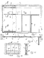
- Fig. 1 is a front view of a partition of the invention,
- Fig. 2 is a section along the line II-II of Fig. 1,
- Fig. 3 is a section along the line III-III of Fig. 1,
- Fig. 4 is a section along the line IV-IV of Fig. 1,
- Fig. 5 is a section along the line V-V of Fig. 1,
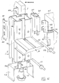
- Fig. 6 is an exploded view of an upright connected to a cross-bar and the members for fixing it to the ground,
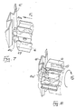
- Fig. 7 is a diagrammatic view of one stage of the connection of a cross-bar to an upright,
- Fig. 8 shows the final stage of the connection of the cross-bar to the upright,
- Fig. 9 shows an alternative form of panelling of the partition,
- Fig. 10 is a diagrammatic view of the electricity and communication lines within the wall,
- Fig. 11 is a section along the line XI-XI of Fig. 10.
- As shown in Figs. 1 and 2, the partition of the invention extends between a pair of
walls 1 facing one another, a floor 2 and a ceiling 3 in order to separate a room of large size into two portions. - The partition substantially comprises a
perimetral frame 4 connected to thewalls 1, floor 2 and ceiling 3 to which frame there is connected a plurality ofuprights 5 bearingrespective cross-bars 6 defining sections of various size within which are disposedcovering panels 7 of the opaque type and possiblytransparent components 8, doors 9 and the like. - If opaque panels of suitable material are used to close these sections, the partition can be fire-resistant in accordance with regulations, so as to stop a fire and its smoke from spreading into the adjacent room portion for a certain period.
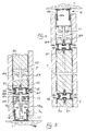
- For this purpose, as shown in Figs. 3, 4, 5 and 6, the
uprights 5 of the partition structure are formed by asteel profile 10, advantageously made of sheet folded and seamed into a tubular shape connected at the ends, viarelative pins 11, to respective upper andlower brackets 12a, 12b provided withflanges 13 and havingbent members 14 designed to fit above theprofiles 15 forming theperimetral frame 4. - As shown in Fig. 3, the
lower brackets 12a are provided with a threadedmember 16 in which the threaded portion of athrust pin 17, bearing within thegroove 18 of theprofile 14, is inserted, via which it is possible to adjust the height of each upright. - The
cross-bars 6 are formed by thesame profiles 10 connected to the upright profiles bycoupling members 19 of metal with suitable properties, for instance sintered steel, connected to the ends of the cross-bars whoseelastic portions 20 may be inserted and locked by friction within thegrooves 21 of theprofiles 10 of the uprights, having undercutsides 22, as shown in Fig. 5. - In this way the cross-bars can be located at the desired heights on the uprights, and are locked in position by friction since they are not subject to loads other than their own weight, which operation can be carried out without special tools.
- Assembly can be carried out in a particularly rapid manner, as shown in Figs. 7 and 8, by inserting the
coupling 19, connected in advance to the relative cross-bar, within thegroove 21 of the upright in the direction of the arrow F1 of Fig. 7, keeping the axis of the cross-bar rotated through 90° with respect to its normal position. - Subsequently, as shown by the arrow F2 in Fig. 8, the cross-bar is rotated through 90°, bringing it into the final position; this rotation determines the contact of the oblique lateral sides 20a of the
elastic portions 20 with theundercut sides 22 of thegroove 21 of the upright; in this position theportions 20 are elastically stressed generating a locking force which keeps the head surface of the cross-bar in forced contact with the side of the upright, thereby ensuring the rigidity of the unit. - The
profiles 10 of the uprights also bearfurther pins 23, projecting transversely from one or both sides of the profile, to which theopaque covering panels 7 may be connected viarespective hooks 24. - The
profiles 10 are also provided with lateral recesses 25, having undercut sides 26, within which there may be housedsealing profiles 27 having flexible members 27a designed to bear against the inner surface of thepanels 7 at the point of junction of adjacent panels thereby ensuring that the panels are dustproof and noiseproof. - Sealing is also carried out at the
profiles 15 of the perimetral frame via a relativeshaped seal 28, having flexible members bearing on the ground and against the end edge of the covering panels. - A skirting panel 7a, provided with snap-
hooks 29 which may be inserted on thepins 11 for fastening the uprights to the brackets, is provided along the lower edge of the partition. - These skirting panels are provided such that they can be assembled independently of the other panels, thereby allowing access, prior to their assembly, to the
pins 17 for the fine adjustment of the base height of the uprights so as to allow the edges of the adjacent panels to be aligned. - During this alignment, the upper brackets 12b can slide telescopically within the
upper profiles 15 of the perimetral frame, thus allowing vertical adjustment via thepins 17 and offsetting any departures from horizontal or undulations in the ceiling. - Fire resistance properties are ensured, in the case of the structure described above, by the fact that the uprights and cross-bars, and the other bearing and reciprocal connection members therefor and the members for their connection to the walls, are made of steel and are therefore subject to structural collapse only at high temperatures substantially greater than the temperatures which can be withstood by the light alloy structures which are conventionally used. In addition, the gap between the
opposite panels 7 is filled with a heat insulating andnon-combustible material 30, for instance mineral wool; fire-resistant profiles 31 of steel are further inserted in a snap-locking manner in the grooves 21: in this way the transmission of the high temperature or any flames on one side of the partition to the panels on the opposite side is considerably delayed, preventing its combustion for a long period. Themineral wool 30 provides heat insulation between thepanels 7 of the two side of the partition, while the direct passage of flames from one side of the partition to the other in the zone of contact between themineral wool 30 and theprofiles 10 of the uprights and cross-bars is prevented by theprofiles 31, embedded in the mineral wool, and creating a kind of labyrinth designed to prevent the passage of the flames. - The presence of the recesses 25 further spaces most of the surfaces of the sides of the
profiles 10 opposite the flames, on one hand, and the panels to be preserved, on the other hand, exposing only athin strip 32 and thus preventing the profiles, of heat conductive material, from transmitting the combustion temperature from one side of the partition to the other in a short period and triggering combustion of the panels on the side to be preserved in the zone of contact or proximity between the panels and the profiles of the uprights and cross-bars. - In order to prevent the passage of smoke through the partition in the case of fire, when the
sealing profiles 27 are made of plastic material, in which case the combustion or melting of the latter occurs and they are unable to carry out their function in these conditions, expanding seals 33 designed to expand with increasing temperature until they seal the spaces between theadjacent panels 7 may also be provided along the entire sides of thepanels 7. - If the sealing profiles are made of ceramic fibre or self-extinguishing material designed to withstand fire for the desired time, the use of expanding seals can be avoided.
- As shown in Fig. 9, the
panels 7 may be made of shaped steel plate instead of chip or synthetic conglomerate materials with a surface coating for aesthetic purposes having self-extinguishing properties or the like, for particular aesthetic, technical or economic reasons and to offer increased fire resistance: in this case theplate 34 has a member forming agroove 35 designed to receive acylindrical seal 36 against which theedge 32 of the uprights and cross-bars bears and which thus extends with aflat edge 37; shaped recesses 38, shown in Fig. 6, are provided on the vertically disposededges 37 and are designed to allow the panel to be hooked to thepins 23 for connection to the uprights of the partition; the elastic deformation of theseals 36 pressed against theedges 32 ensures a vibration-free connection. - The filling 30 of heat and sound insulating material may thus be inserted in the space between two panels of this type facing one another.
- In the case of panels constructed in this way the
profiles 31 may be omitted, since thegrooves 35 formed by theplate 34 form a labyrinth which is sufficient to prevent, in the event of fire, the direct passage of flames and heat. - The
plate 34 may thus be covered, painted or the like in accordance with requirements and may have dimensions and an external appearance which are compatible with and correspond to that of panels of the solid type, allowing, if desired, the simultaneous use ofpanels 7 of different types without any aesthetic discontinuity. -
Rack profiles 39, formed by a U-shaped component provided with uniformly spacedholes 40, as shown in Fig. 6, may advantageously be connected, via screws or the like, within the recesses 25 of theprofiles 10 of the uprights, which rack profiles make it possible to connect accessories ofvarious types 41, viarelative hooks 42, to the uprights, as shown in Fig. 6, for example brackets, cupboards, shelves and the like, without having to carry out any machining operations such as drilling or the like and such that the position and type of accessory can be changed at any time. - The
profiles 39 are connected to theprofiles 10, externally to theseals 27, via screws or the like. - The
panels 7 leave a space between each other which can be used to house thefilling 30 and which may also house a plurality of electric andconnection cables 43, as shown in Figs. 10 and 11, which may extend either into thefront face 44 of the partition,holes 45 ensuring a continuous passage for the cables being provided in the uprights for this purpose, or along theperimetral profiles 4 thus allowing, by relative connection points, located wherever desired along the path of the cables, the full connection of apparatus of all types, such as lighting plant, computers, telephones and the like, without the presence of external cables. - It is also possible to dispose
transparent components 8 in the partition; the doors 9 which can be inserted in the structure can be constructed in a fire resistant way using suitable materials or can be of a non-resistant type if this requirement is not needed. - If it is desired to provide a different type of screening, together with or as an alternative to the fire screening and its effects, such as screening against heat, smoke or the like, for instance the provision of soundproofing, insulation against humidity, radiation, screening against mechanical drilling and the like, screening members with appropriate properties can be inserted in the
grooves 21 of the profiles of the uprights and cross-bars, selecting appropriate properties for the fillingmaterial 30. - If total screening against fire or other disturbances is not required, as mentioned above, or if a partial and local action is sufficient, the partition of the invention may be formed in different shapes, for example extending vertically over only a fraction of the overall height between floor and ceiling, or extending halfway into the room, or may be provided with communication openings and doors between separate rooms, etc; closure profiles should advantageously be provided in these embodiments, for aesthetic reasons, and may be of steel or other materials such as light alloys, plastic materials and the like.
- The partition may also be connected, without aesthetic discontinuity, to partitions of different type, such as shelving partitions, or to furniture, desks, tables and the like, connected on one side, for instance, to the
racks 39; even in these cases the continuity of the passage of electric andcommunication cables 43 may be ensured. - Many variants may be made without departing form the general scope of the invention.
Claims (11)
Applications Claiming Priority (2)
| Application Number | Priority Date | Filing Date | Title |
|---|---|---|---|
| IT21595/87A IT1222449B (en) | 1987-08-06 | 1987-08-06 | INTERIOR DIVIDING WALL COMPONIBLE WITH FIRE-SHIELDING PROPERTIES AND SIMILAR |
| IT2159587 | 1987-08-06 |
Publications (2)
| Publication Number | Publication Date |
|---|---|
| EP0302564A2 true EP0302564A2 (en) | 1989-02-08 |
| EP0302564A3 EP0302564A3 (en) | 1990-05-02 |
Family
ID=11184107
Family Applications (1)
| Application Number | Title | Priority Date | Filing Date |
|---|---|---|---|
| EP88201641A Withdrawn EP0302564A3 (en) | 1987-08-06 | 1988-07-29 | Modular internal partition with fire-screening and like properties |
Country Status (3)
| Country | Link |
|---|---|
| US (1) | US4914880A (en) |
| EP (1) | EP0302564A3 (en) |
| IT (1) | IT1222449B (en) |
Cited By (21)
| Publication number | Priority date | Publication date | Assignee | Title |
|---|---|---|---|---|
| FR2643700A1 (en) * | 1989-02-28 | 1990-08-31 | Atal | Panel-support section, associated panel-fixing device, and device for assembling lengths of section |
| EP0507713A1 (en) * | 1991-04-05 | 1992-10-07 | Clestra Hauserman, S.A. | Partition with capacity for long-lasting fire resistance |
| EP0756044A1 (en) * | 1995-07-24 | 1997-01-29 | BRIOUDE FABRICATION Société Anonyme | System for interior arrangement or invisible fastener device for panels or facing panels |
| EP0911454A3 (en) * | 1997-10-20 | 2000-11-08 | G + H Montage Gmbh | Certified fireproof partioning wall |
| EP1092815A1 (en) * | 1999-10-15 | 2001-04-18 | Campenon Bernard SGE | Fire-resistant partition |
| WO2002075067A1 (en) * | 2001-03-21 | 2002-09-26 | Me. Tra. Metallurgica | Supporting construction for movable walls and the like |
| US6865853B2 (en) * | 2003-01-31 | 2005-03-15 | Hon Technology Inc. | Base assembly for wall panel construction |
| DE102006050230A1 (en) * | 2006-10-17 | 2008-04-24 | Ritterwand Gmbh & Co. Kg Metall-Systembau | Floor connecting unit for providing passage to floor, has projection formed such that groove-shaped hollow chamber is formed between floor and floor connecting unit, where hollow chamber is accessible from outside |
| ES2325893A1 (en) * | 2005-02-17 | 2009-09-23 | Metal Work S.R.L. | Structure for supporting elements to form a wall |
| ITPR20090025A1 (en) * | 2009-04-15 | 2010-10-16 | Coopsette Societa Cooperativa | MULTI-FUNCTION PARIETAL STRUCTURE |
| NL2010367C2 (en) * | 2013-02-27 | 2014-08-28 | Maars Holding Bv | WALL. |
| US9943165B2 (en) | 2016-02-10 | 2018-04-17 | Dirtt Environmental Solutions, Ltd. | Embedded furniture having retractible legs with lighting |
| CN108118807A (en) * | 2018-02-05 | 2018-06-05 | 中国新兴建筑工程有限责任公司 | A kind of steel framework concrete partition and its construction method |
| USRE46929E1 (en) | 2004-08-17 | 2018-07-03 | Dirtt Environmental Solutions, Ltd | Integrated reconfigurable wall system |
| CN109779093A (en) * | 2017-11-11 | 2019-05-21 | 天津二建水电安装工程有限公司 | A kind of light partition wall and its construction method |
| US10920418B2 (en) | 2011-12-28 | 2021-02-16 | Dirtt Environmental Solutions, Ltd | Modular walls incorporating recessed, extendable furniture |
| US11085184B2 (en) | 2014-02-20 | 2021-08-10 | Dirtt Environmental Solutions Ltd. | Interface for mounting interchangable components |
| US11093087B2 (en) | 2016-06-10 | 2021-08-17 | Dirtt Environmental Solutions Ltd. | Glass substrates with touchscreen technology |
| US11240922B2 (en) | 2016-06-10 | 2022-02-01 | Dirtt Environmental Solutions Ltd. | Wall system with electronic device mounting assembly |
| US20220364359A1 (en) * | 2019-12-10 | 2022-11-17 | Dirtt Environmental Solutions Ltd. | Wall leveler and floor interfacing component system |
| US11550178B2 (en) | 2016-07-08 | 2023-01-10 | Dirtt Environmental Solutions Inc. | Low-voltage smart glass |
Families Citing this family (48)
| Publication number | Priority date | Publication date | Assignee | Title |
|---|---|---|---|---|
| US5214817A (en) * | 1991-06-24 | 1993-06-01 | Allen James E | Modular ramp and landing walkway assembly |
| US5203132A (en) * | 1991-09-17 | 1993-04-20 | Smolik Robert A | Wall assembly |
| US5724784A (en) | 1992-03-27 | 1998-03-10 | National Gypsum Company | Shaft wall and horizontal metal stud therefor |
| CA2109676C (en) | 1993-02-25 | 2002-04-30 | Robert J. Menchetti | Multiple use corner clip |
| CA2095758A1 (en) | 1993-02-25 | 1994-08-26 | Robert J. Menchetti | Corner clips for horizontal framing |
| US5746034B1 (en) * | 1994-12-30 | 2000-10-17 | Steelcase Inc | Partition system |
| US5740644A (en) | 1995-02-08 | 1998-04-21 | National Gypsum Company | Wall with horizontal metal stud and reinforcement channel therefor |
| US5950386A (en) | 1995-12-26 | 1999-09-14 | Steelcase Inc. | Partition construction having frame and misaligned covers |
| US5836121A (en) * | 1996-07-26 | 1998-11-17 | Steelcase Inc. | Connection system for connecting partition and floor channel |
| US6546684B2 (en) | 1998-04-15 | 2003-04-15 | Steelcase Development Corporation | Partition panel |
| US6301846B1 (en) | 1996-12-24 | 2001-10-16 | Steelcase Development Inc. | Knock-down portable partition system |
| US5899035A (en) * | 1997-05-15 | 1999-05-04 | Steelcase, Inc. | Knock-down portable partition system |
| US6910306B2 (en) | 1996-12-24 | 2005-06-28 | Steelcase Development Corporation | Knock-down portable partition system |
| US6105322A (en) * | 1998-08-06 | 2000-08-22 | Chang; Ching-Chang | Combination partition wall |
| US6122871A (en) * | 1998-11-19 | 2000-09-26 | Steelcase Development Inc. | Wall-to-ceiling structure including framework and cover panel |
| US6094872A (en) * | 1999-10-08 | 2000-08-01 | Steelcase Development Inc. | Partition and floor channel construction |
| CA2329591A1 (en) * | 2000-12-22 | 2002-06-22 | Eberhard Von Hoyningen Huene | Demountable partition system |
| US6510807B2 (en) * | 2001-01-26 | 2003-01-28 | No Fire Technologies, Inc. | Pre-fabricated fireproof bulkhead with special interlocking joints for a ship |
| DE10124733A1 (en) * | 2001-05-21 | 2002-11-28 | Geze Glas Design Gmbh | Device for height adjustment of a partition |
| US20030155318A1 (en) * | 2002-02-15 | 2003-08-21 | Kenneth Jacobs | Modular stanchion storage structure |
| US20050000168A1 (en) * | 2003-07-03 | 2005-01-06 | David Wright | Modular office panels |
| US7334377B2 (en) * | 2003-08-14 | 2008-02-26 | Johnson Controls Technology Company | Raceway construction for an air handing unit |
| FR2863284B1 (en) * | 2003-12-05 | 2007-11-23 | Placoplatre Sa | DEVICE FOR THE PARASISMIC MOUNTING OF A CLOISON |
| US8517809B2 (en) * | 2006-04-12 | 2013-08-27 | Zero International, Inc. | Louver closure system and method |
| US20080209827A1 (en) * | 2007-01-16 | 2008-09-04 | Webb Scott T | Temporary movable/removable compression partition wall system |
| US7941975B2 (en) * | 2007-04-11 | 2011-05-17 | Erla Dogg Ingjaldsdottir | Affordable, sustainable buildings comprised of recyclable materials and methods thereof |
| US8429871B2 (en) * | 2007-04-11 | 2013-04-30 | Erla Dögg Ingjaldsdottir | Affordable, sustainable buildings comprised of recyclable materials and methods thereof |
| US10563399B2 (en) | 2007-08-06 | 2020-02-18 | California Expanded Metal Products Company | Two-piece track system |
| US10619347B2 (en) | 2007-08-22 | 2020-04-14 | California Expanded Metal Products Company | Fire-rated wall and ceiling system |
| ITBO20080671A1 (en) * | 2008-11-06 | 2010-05-07 | Deal S R L | MODULAR WALL MOUNTED DEVICE |
| US8671632B2 (en) * | 2009-09-21 | 2014-03-18 | California Expanded Metal Products Company | Wall gap fire block device, system and method |
| US10184246B2 (en) | 2010-04-08 | 2019-01-22 | California Expanded Metal Products Company | Fire-rated wall construction product |
| US9284729B2 (en) | 2010-05-05 | 2016-03-15 | Allsteel Inc. | Modular wall system |
| CA2796997C (en) | 2011-06-11 | 2016-05-10 | Dirtt Environmental Solutions, Ltd. | Modular wall nesting system |
| US10077550B2 (en) | 2012-01-20 | 2018-09-18 | California Expanded Metal Products Company | Fire-rated joint system |
| US12215498B2 (en) | 2012-01-20 | 2025-02-04 | Cemco, Llc | Fire-rated joint system |
| US9045896B2 (en) | 2012-09-17 | 2015-06-02 | Steelcase Inc. | Floor-to-ceiling partition wall assembly |
| WO2015009496A1 (en) | 2013-07-16 | 2015-01-22 | Wickstrom Benjamin D | Cleanroom wall panel system, and method |
| AU2019230454B2 (en) * | 2018-03-06 | 2025-02-27 | Systems Pty Ltd | A locking assembly for securing one or more building elements in a building system |
| US10689842B2 (en) | 2018-03-15 | 2020-06-23 | California Expanded Metal Products Company | Multi-layer fire-rated joint component |
| US10753084B2 (en) | 2018-03-15 | 2020-08-25 | California Expanded Metal Products Company | Fire-rated joint component and wall assembly |
| US11162259B2 (en) | 2018-04-30 | 2021-11-02 | California Expanded Metal Products Company | Mechanically fastened firestop flute plug |
| US11111666B2 (en) | 2018-08-16 | 2021-09-07 | California Expanded Metal Products Company | Fire or sound blocking components and wall assemblies with fire or sound blocking components |
| US10914065B2 (en) | 2019-01-24 | 2021-02-09 | California Expanded Metal Products Company | Wall joint or sound block component and wall assemblies |
| WO2020174289A2 (en) * | 2019-02-27 | 2020-09-03 | Louisiana-Pacific Corporation | Fire-resistant manufactured-wood based siding |
| US11268274B2 (en) | 2019-03-04 | 2022-03-08 | California Expanded Metal Products Company | Two-piece deflection drift angle |
| US11920343B2 (en) | 2019-12-02 | 2024-03-05 | Cemco, Llc | Fire-rated wall joint component and related assemblies |
| US12454824B2 (en) | 2020-08-19 | 2025-10-28 | Cemco, Llc | Building joint with compressible firestopping component |
Family Cites Families (24)
| Publication number | Priority date | Publication date | Assignee | Title |
|---|---|---|---|---|
| US3124222A (en) * | 1964-03-10 | Wall panel | ||
| US1420473A (en) * | 1920-12-14 | 1922-06-20 | Carl E Dawson | Partition for buildings |
| US3078968A (en) * | 1958-10-02 | 1963-02-26 | Harvey Aluminum Inc | Prefabricated partitioning |
| US3189140A (en) * | 1959-08-05 | 1965-06-15 | Designs For Business Inc | Partitioning system |
| US3034609A (en) * | 1960-07-11 | 1962-05-15 | Unistrut Products Company | Building partition structure |
| US3261625A (en) * | 1961-12-27 | 1966-07-19 | Reynolds Metals Co | Joint between vertical and horizontal members in a partition construction |
| GB1018945A (en) * | 1963-05-16 | 1966-02-02 | Robert Charles Rolland | Wall structure |
| FR1435227A (en) * | 1965-03-16 | 1966-04-15 | Assembly device and parts for the execution of panels, partitions and similar constructions | |
| US3371454A (en) * | 1965-10-24 | 1968-03-05 | Anderson Mfg Co V E | Partition structure |
| US3550338A (en) * | 1968-10-09 | 1970-12-29 | Architectural Partitions | Wall structure |
| US3694975A (en) * | 1970-07-27 | 1972-10-03 | Mills Co The | Partition structure |
| FR2238020A1 (en) * | 1973-07-19 | 1975-02-14 | Pollet Sa | Fire resistant partition wall panels - are erected on vert. grid allowing warping and expansion without collapsing |
| US4027444A (en) * | 1973-10-19 | 1977-06-07 | Adolf Berg | Fire-resistant walls for use in shipbuilding |
| DE2427997C2 (en) * | 1974-06-10 | 1982-05-19 | Furnier- Und Sperrholzwerk J.F. Werz Jr. Kg Werzalit-Pressholzwerk, 7141 Oberstenfeld | Movable partition |
| US4057123A (en) * | 1975-12-03 | 1977-11-08 | Conwed Corporation | Lightweight sound absorbent panels having high noise reduction coefficient |
| CH629885A5 (en) * | 1978-04-05 | 1982-05-14 | Syma Intercontinental Sa | Profile with undercut longitudinal grooves for a frame |
| DE8015385U1 (en) * | 1980-06-10 | 1985-11-21 | Stierlen-Maquet Ag, 7550 Rastatt | Kit for lining, delimiting and dividing rooms |
| ES256936Y (en) * | 1981-03-16 | 1982-06-01 | SELF-SUPPORTING METAL STRUCTURE FOR INTERIOR WALLS | |
| US4395856A (en) * | 1981-10-01 | 1983-08-02 | Smith David L | Post and panel mounting system |
| US4535577A (en) * | 1982-12-15 | 1985-08-20 | Global Upholstery Company Limited | Office panelling system |
| FR2546209B1 (en) * | 1983-05-17 | 1985-08-23 | Pjb Cloisons Amovibles | PROFILE FOR THE CONSTRUCTION OF PARTITIONS, METHOD OF USING THE SAME AND PARTITIONS OBTAINED BY ITS IMPLEMENTATION |
| US4567698A (en) * | 1983-12-13 | 1986-02-04 | Knoll International, Inc. | Space divider system |
| DE3345747A1 (en) * | 1983-12-17 | 1985-06-27 | Howaldtswerke - Deutsche Werft AG Hamburg und Kiel, 2300 Kiel | Fire-retarding wall elements with connecting devices |
| DE3508078A1 (en) * | 1985-03-07 | 1986-09-18 | Leininger-Brandschutzelemente GmbH, 5000 Köln | Fire-retarding partition wall |
-
1987
- 1987-08-06 IT IT21595/87A patent/IT1222449B/en active
-
1988
- 1988-07-18 US US07/220,525 patent/US4914880A/en not_active Expired - Fee Related
- 1988-07-29 EP EP88201641A patent/EP0302564A3/en not_active Withdrawn
Cited By (34)
| Publication number | Priority date | Publication date | Assignee | Title |
|---|---|---|---|---|
| FR2643700A1 (en) * | 1989-02-28 | 1990-08-31 | Atal | Panel-support section, associated panel-fixing device, and device for assembling lengths of section |
| EP0507713A1 (en) * | 1991-04-05 | 1992-10-07 | Clestra Hauserman, S.A. | Partition with capacity for long-lasting fire resistance |
| FR2674885A1 (en) * | 1991-04-05 | 1992-10-09 | Clestra Hauserman Sa | PARTITION DEVICE, PARTICULARLY WITH FIRE - RESISTANT CAPACITY DURING A LONG DURATION. |
| EP0756044A1 (en) * | 1995-07-24 | 1997-01-29 | BRIOUDE FABRICATION Société Anonyme | System for interior arrangement or invisible fastener device for panels or facing panels |
| FR2737264A1 (en) * | 1995-07-24 | 1997-01-31 | Brioude Fabrication Sa | INVISIBLE HANGING DEVICE FOR PANELS OR PLATE PANELS AND INTERIOR ARRANGEMENT SYSTEM BY APPLYING |
| EP0911454A3 (en) * | 1997-10-20 | 2000-11-08 | G + H Montage Gmbh | Certified fireproof partioning wall |
| EP1092815A1 (en) * | 1999-10-15 | 2001-04-18 | Campenon Bernard SGE | Fire-resistant partition |
| FR2799779A1 (en) * | 1999-10-15 | 2001-04-20 | Campenon Bernard Sge | FIREWALL PARTITION |
| WO2001029340A1 (en) * | 1999-10-15 | 2001-04-26 | Campenon Bernard Sge | Fire-resisting partition |
| WO2002075067A1 (en) * | 2001-03-21 | 2002-09-26 | Me. Tra. Metallurgica | Supporting construction for movable walls and the like |
| US6865853B2 (en) * | 2003-01-31 | 2005-03-15 | Hon Technology Inc. | Base assembly for wall panel construction |
| USRE46929E1 (en) | 2004-08-17 | 2018-07-03 | Dirtt Environmental Solutions, Ltd | Integrated reconfigurable wall system |
| USRE47693E1 (en) | 2004-08-17 | 2019-11-05 | Dirtt Environmental Solutions, Ltd. | Integrated reconfigurable wall system |
| USRE47132E1 (en) | 2004-08-17 | 2018-11-20 | Dirtt Environmental Solutions, Ltd | Integrated reconfigurable wall system |
| ES2325893A1 (en) * | 2005-02-17 | 2009-09-23 | Metal Work S.R.L. | Structure for supporting elements to form a wall |
| ES2325893B1 (en) * | 2005-02-17 | 2010-07-08 | Metal Work S.R.L. | STRUCTURE FOR THE HOLDING OF ELEMENTS TO DEFINE A WALL. |
| DE102006050230A1 (en) * | 2006-10-17 | 2008-04-24 | Ritterwand Gmbh & Co. Kg Metall-Systembau | Floor connecting unit for providing passage to floor, has projection formed such that groove-shaped hollow chamber is formed between floor and floor connecting unit, where hollow chamber is accessible from outside |
| DE102006050230B4 (en) * | 2006-10-17 | 2011-03-17 | Ritterwand Gmbh & Co. Kg Metall-Systembau | Ground terminal |
| ITPR20090025A1 (en) * | 2009-04-15 | 2010-10-16 | Coopsette Societa Cooperativa | MULTI-FUNCTION PARIETAL STRUCTURE |
| US10920418B2 (en) | 2011-12-28 | 2021-02-16 | Dirtt Environmental Solutions, Ltd | Modular walls incorporating recessed, extendable furniture |
| NL2010367C2 (en) * | 2013-02-27 | 2014-08-28 | Maars Holding Bv | WALL. |
| WO2014133388A1 (en) * | 2013-02-27 | 2014-09-04 | Maars Holding B.V. | Partition wall system including clamping of the panels |
| US9506246B2 (en) | 2013-02-27 | 2016-11-29 | Maars Holding B.V. | Partition wall system including clamping of the panels |
| US11085184B2 (en) | 2014-02-20 | 2021-08-10 | Dirtt Environmental Solutions Ltd. | Interface for mounting interchangable components |
| US10058170B2 (en) | 2016-02-10 | 2018-08-28 | Dirtt Environmental Solutions, Ltd | Modular walls with embedded furniture and opposing feature |
| US9943165B2 (en) | 2016-02-10 | 2018-04-17 | Dirtt Environmental Solutions, Ltd. | Embedded furniture having retractible legs with lighting |
| US11240922B2 (en) | 2016-06-10 | 2022-02-01 | Dirtt Environmental Solutions Ltd. | Wall system with electronic device mounting assembly |
| US11093087B2 (en) | 2016-06-10 | 2021-08-17 | Dirtt Environmental Solutions Ltd. | Glass substrates with touchscreen technology |
| US11550178B2 (en) | 2016-07-08 | 2023-01-10 | Dirtt Environmental Solutions Inc. | Low-voltage smart glass |
| CN109779093B (en) * | 2017-11-11 | 2020-08-11 | 天津建工城市建设发展有限公司 | Light partition wall and construction method thereof |
| CN109779093A (en) * | 2017-11-11 | 2019-05-21 | 天津二建水电安装工程有限公司 | A kind of light partition wall and its construction method |
| CN108118807A (en) * | 2018-02-05 | 2018-06-05 | 中国新兴建筑工程有限责任公司 | A kind of steel framework concrete partition and its construction method |
| US20220364359A1 (en) * | 2019-12-10 | 2022-11-17 | Dirtt Environmental Solutions Ltd. | Wall leveler and floor interfacing component system |
| US12000143B2 (en) * | 2019-12-10 | 2024-06-04 | Dirtt Environmental Solutions Ltd. | Wall leveler and floor interfacing component system |
Also Published As
| Publication number | Publication date |
|---|---|
| IT1222449B (en) | 1990-09-05 |
| IT8721595A0 (en) | 1987-08-06 |
| US4914880A (en) | 1990-04-10 |
| EP0302564A3 (en) | 1990-05-02 |
Similar Documents
| Publication | Publication Date | Title |
|---|---|---|
| EP0302564A2 (en) | Modular internal partition with fire-screening and like properties | |
| CA1328972C (en) | Horizontally oriented demountable partition system | |
| US4852317A (en) | Demountable panel system | |
| US4356672A (en) | Partitioning system | |
| US7540115B2 (en) | Partition system | |
| US8393122B2 (en) | Partition system | |
| US6158178A (en) | Panel wall construction | |
| US5345737A (en) | System of modular building elements for display fixtures | |
| US5135194A (en) | Wall mounting system | |
| US6128877A (en) | Variable width end panel | |
| US5930963A (en) | Wall panel system | |
| US4836625A (en) | Console structure | |
| US5020290A (en) | Modular wall | |
| US5325641A (en) | System for mounting a wall panel | |
| US6481163B1 (en) | Partition panel | |
| US2965428A (en) | Domestic appliance | |
| US20050034378A1 (en) | Partition system | |
| US4356674A (en) | Free-standing space divider assembly with acoustic upper end border | |
| CA1294107C (en) | Demountable panel system | |
| US4713920A (en) | Modular tongue and groove removable panel partition system | |
| US5090163A (en) | Easily accessible smoke curtain assembly | |
| JP4940029B2 (en) | Continuous panel wall structure | |
| CN214230567U (en) | Wall cabinet subassembly and assembled kitchen | |
| KR200228552Y1 (en) | Prefabricated partition | |
| US5848774A (en) | Air curtain mounting plate and structure |
Legal Events
| Date | Code | Title | Description |
|---|---|---|---|
| PUAI | Public reference made under article 153(3) epc to a published international application that has entered the european phase |
Free format text: ORIGINAL CODE: 0009012 |
|
| AK | Designated contracting states |
Kind code of ref document: A2 Designated state(s): ES FR GB IT |
|
| PUAL | Search report despatched |
Free format text: ORIGINAL CODE: 0009013 |
|
| AK | Designated contracting states |
Kind code of ref document: A3 Designated state(s): ES FR GB IT |
|
| 17P | Request for examination filed |
Effective date: 19901023 |
|
| 17Q | First examination report despatched |
Effective date: 19911104 |
|
| STAA | Information on the status of an ep patent application or granted ep patent |
Free format text: STATUS: THE APPLICATION HAS BEEN WITHDRAWN |
|
| 18W | Application withdrawn |
Withdrawal date: 19930517 |