US5870867A - Solid core partition wall - Google Patents
Solid core partition wall Download PDFInfo
- Publication number
- US5870867A US5870867A US08/763,698 US76369896A US5870867A US 5870867 A US5870867 A US 5870867A US 76369896 A US76369896 A US 76369896A US 5870867 A US5870867 A US 5870867A
- Authority
- US
- United States
- Prior art keywords
- panels
- studs
- wall
- core
- panel
- Prior art date
- Legal status (The legal status is an assumption and is not a legal conclusion. Google has not performed a legal analysis and makes no representation as to the accuracy of the status listed.)
- Expired - Fee Related
Links
- 239000007787 solid Substances 0.000 title claims abstract description 74
- 238000005192 partition Methods 0.000 title description 18
- 229910052602 gypsum Inorganic materials 0.000 claims abstract description 19
- 239000010440 gypsum Substances 0.000 claims abstract description 19
- 239000002184 metal Substances 0.000 claims description 7
- 239000011230 binding agent Substances 0.000 description 6
- 238000010276 construction Methods 0.000 description 4
- 238000001125 extrusion Methods 0.000 description 3
- 238000009434 installation Methods 0.000 description 3
- 230000013011 mating Effects 0.000 description 3
- 238000004873 anchoring Methods 0.000 description 2
- 230000008901 benefit Effects 0.000 description 2
- 238000005553 drilling Methods 0.000 description 2
- 239000000463 material Substances 0.000 description 2
- 239000004020 conductor Substances 0.000 description 1
- 230000003467 diminishing effect Effects 0.000 description 1
- 230000001747 exhibiting effect Effects 0.000 description 1
- 230000009970 fire resistant effect Effects 0.000 description 1
- 239000011521 glass Substances 0.000 description 1
- 238000009413 insulation Methods 0.000 description 1
- 230000004048 modification Effects 0.000 description 1
- 238000012986 modification Methods 0.000 description 1
- 239000003973 paint Substances 0.000 description 1
- 229920006327 polystyrene foam Polymers 0.000 description 1
- 125000000391 vinyl group Chemical group [H]C([*])=C([H])[H] 0.000 description 1
- 229920002554 vinyl polymer Polymers 0.000 description 1
Images


Classifications
-
- E—FIXED CONSTRUCTIONS
- E04—BUILDING
- E04B—GENERAL BUILDING CONSTRUCTIONS; WALLS, e.g. PARTITIONS; ROOFS; FLOORS; CEILINGS; INSULATION OR OTHER PROTECTION OF BUILDINGS
- E04B2/00—Walls, e.g. partitions, for buildings; Wall construction with regard to insulation; Connections specially adapted to walls
- E04B2/74—Removable non-load-bearing partitions; Partitions with a free upper edge
- E04B2/7407—Removable non-load-bearing partitions; Partitions with a free upper edge assembled using frames with infill panels or coverings only; made-up of panels and a support structure incorporating posts
- E04B2/7453—Removable non-load-bearing partitions; Partitions with a free upper edge assembled using frames with infill panels or coverings only; made-up of panels and a support structure incorporating posts with panels and support posts, extending from floor to ceiling
- E04B2/7457—Removable non-load-bearing partitions; Partitions with a free upper edge assembled using frames with infill panels or coverings only; made-up of panels and a support structure incorporating posts with panels and support posts, extending from floor to ceiling with wallboards attached to the outer faces of the posts, parallel to the partition
-
- E—FIXED CONSTRUCTIONS
- E04—BUILDING
- E04B—GENERAL BUILDING CONSTRUCTIONS; WALLS, e.g. PARTITIONS; ROOFS; FLOORS; CEILINGS; INSULATION OR OTHER PROTECTION OF BUILDINGS
- E04B1/00—Constructions in general; Structures which are not restricted either to walls, e.g. partitions, or floors or ceilings or roofs
- E04B1/38—Connections for building structures in general
- E04B1/61—Connections for building structures in general of slab-shaped building elements with each other
- E04B1/6104—Connections for building structures in general of slab-shaped building elements with each other the overlapping ends of the slabs connected together
-
- E—FIXED CONSTRUCTIONS
- E04—BUILDING
- E04B—GENERAL BUILDING CONSTRUCTIONS; WALLS, e.g. PARTITIONS; ROOFS; FLOORS; CEILINGS; INSULATION OR OTHER PROTECTION OF BUILDINGS
- E04B2/00—Walls, e.g. partitions, for buildings; Wall construction with regard to insulation; Connections specially adapted to walls
- E04B2/74—Removable non-load-bearing partitions; Partitions with a free upper edge
- E04B2002/7483—Details of furniture, e.g. tables or shelves, associated with the partitions
-
- E—FIXED CONSTRUCTIONS
- E04—BUILDING
- E04B—GENERAL BUILDING CONSTRUCTIONS; WALLS, e.g. PARTITIONS; ROOFS; FLOORS; CEILINGS; INSULATION OR OTHER PROTECTION OF BUILDINGS
- E04B2/00—Walls, e.g. partitions, for buildings; Wall construction with regard to insulation; Connections specially adapted to walls
- E04B2/74—Removable non-load-bearing partitions; Partitions with a free upper edge
- E04B2002/7487—Partitions with slotted profiles
-
- E—FIXED CONSTRUCTIONS
- E04—BUILDING
- E04B—GENERAL BUILDING CONSTRUCTIONS; WALLS, e.g. PARTITIONS; ROOFS; FLOORS; CEILINGS; INSULATION OR OTHER PROTECTION OF BUILDINGS
- E04B2/00—Walls, e.g. partitions, for buildings; Wall construction with regard to insulation; Connections specially adapted to walls
- E04B2/74—Removable non-load-bearing partitions; Partitions with a free upper edge
- E04B2002/7488—Details of wiring
Definitions
- This invention relates to walls systems which can be reconfigured and reused as needed, and more particularly to a reconfigurable wall system having solid core panels which provide improved fire resistance and acoustical resistance.
- Wall panel systems for interior construction in buildings are well known.
- conventional interior wall panel systems are generally comprised of a plurality of interconnected hollow core partition panels, which in many cases do not provide adequate acoustical resistance, and which provide less fire resistance than might be desired.
- Known wall panel systems which are comprised of solid core panels, such as gypsum wall panels, are not interconnected in edge to edge relationship, but are instead connected to studs which are interposed between adjacent panels. The studs in these wall systems are generally hollow.
- the hollow studs provide an acoustic gap having a lower acoustic resistance than the solid core wall panels connected thereto, thus diminishing the benefits of the acoustic insulating properties of the solid core wall panels. Therefore, because of the hollow studs, known wall systems incorporating solid core wall panels do not achieve optimum utilization of the sound insulating properties of the solid core panels.
- the hollow studs may also provide reduced fire resistance as compared with the solid core wall panels attached thereto, thus acting as gaps which are susceptible to fire propagation in an otherwise relatively fire resistant wall.
- the known wall panel systems incorporating solid core wall panels do not facilitate selection of a variety of different wall coverings or skins which can be easily installed and dismounted and replaced with different wall coverings as desired.
- the known partition systems incorporating solid core wall panels generally have gypsum outer panels or other surfaces which can be painted or provided with a desired wall covering, such as wallpaper, which must be recovered in a conventional manner if a different wall covering is desired.
- a further disadvantage with known wall panel systems incorporating solid core wall panels is that the do not provide means for facilitating utility modules, such as for supporting an electrical receptacle, means for facilitating mounting of furniture to the wall system, or means for facilitating connection of perpendicular walls (off-walls) off of the wall systems from generally any selected location along the wall system.
- U.S. Pat. No. 4,356,672 to Beckman discloses a partition system including gypsum sheets that can be covered with paneling, wallpaper, paint or other materials.
- Beckman does not disclose a solid core wall, but instead discloses a wall having an internal space therein.
- U.S. Pat. No. 5,287,675 to McGee discloses a wall stud assembly including a solid wall interconnected by studs located between the solid wall sections. The solid wall sections extend between a ceiling channel and a floor channel. The studs between adjacent solid wall sections is generally hollow, thus providing an acoustical gap which may also be more susceptible to fire propagation than the panels connected thereto.
- the solid core panels disclosed by McGee are not comprised of solid gypsum, but instead are comprised of a honeycomb core with vinyl covered hardboard on each side, or a non-combustible insulating core such as polystyrene foam with gypsum panels laminated to outer sides thereof.
- U.S. Pat. No. 4,881,352 to Glockstiein discloses a wall having gypsum panels secured to opposing sides of a centrally located metal stud. The wall disclosed by Glockstiein is filled with a material which provides thermal and acoustic insulating properties.
- U.S. Pat. No. 3,462,892 discloses an adaptor wall having utility modules supported in the wall, but the wall is hollow and does not include a solid core.
- a reconfigurable and reusable wall system incorporating solid core panels which are arranged to provide improved fire resistance and acoustical resistance. It is a further object of this invention to provide a solid core partition wall system which is reconfigurable and reusable, provides improved fire resistance and acoustical resistance, and which extends from floor to ceiling to provide a level of privacy equivalent to that of a conventional permanent drywall construction. Another object of this invention is to provide a solid core partition wall which is reconfigurable and reusable, which will provide improved fire resistance and acoustical resistance, and which includes means for releasably attaching an outer covering or skin thereto.
- a still further object of this invention is to provide a reconfigurable and reusable solid core partition wall system exhibiting improved fire resistance and acoustical resistance, and having means for facilitating mounting of utility modules, such as for electrical receptacles, means for mounting furniture to the wall system, and means for facilitating attachment of walls from the partition system at generally any location along the wall system.
- a reconfigurable and reusable wall panel system includes solid core partition wall panels which are interconnected in a manner which achieves improved fire resistance and acoustical resistance.
- the modular wall system includes a plurality of wall panels having a solid structural core, and which are connected directly to each other in edge to edge relationship.
- the system also includes a plurality of spaced apart structural studs which are attached to opposite faces of the wall panels, and a plurality of cover panels which are attached to outboard faces of the studs.
- the edge to edge connection between adjacent solid core partition wall panels eliminates the need for hollow studs interposed between adjacent wall panels, thus providing a substantially continuous solid core wall which extends along the entire length of the wall system.
- the structural studs which are attached to the opposite faces of the solid core partition wall panels provide means for releasably attaching wall covering panels to the modular wall system.
- the core wall panels include a solid structural core comprising off-set gypsum panels which form opposing lip edges, each of which is adapted to connect to an adjacent core wall panel. More specifically, the lip edge of each panel overlaps a lip edge of an adjacent panel to form a lapped joint which provides improved sound and fire insulation properties as compared with known solid core wall panel systems.
- a particular aspect of the invention is the provision of a modular wall system having solid core partition wall panels which provide improved fire resistance and acoustical resistance, and which includes means for mounting electrical receptacles and/or other utilities in the wall system.
- the system includes a plurality of interconnected panels, each of which has a solid structural core; a plurality of spaced apart structural studs attached to opposite faces of the panels; a plurality of cover panels attached to outboard faces of the studs; and a utility module positioned in a cut-out aperture in one of the solid core panels and supported by adjacent studs.
- a solid core wall panel system having improved fire resistance and acoustical resistance is provided with a horizontal support strap or rail for supporting furniture, wall coverings or skins, or brackets for connecting an off-wall perpendicular to the wall system.
- the solid core partition wall panels and wall systems provide better acoustic and fire resistance properties, are reconfigurable and reusable, can be configured for floor to ceiling privacy, and include releasably attached wall coverings or skins which allow greater flexibility in the selection of wall coverings and allow wall coverings to be changed more easily if desired. Because the wall systems are reconfigurable and reusable, rather than a permanent architectural feature of a building, they can have a lower life cycle cost than drywall construction which must be torn down and disposed of if reconfiguration of walls is required. Additionally, because the wall systems are reconfigurable and reusable, ownership can remain with a building tenant, so that the building tenant can disassemble the wall system and transport it and reuse it at a different location if desired.
- the wall system is portable, rather than a permanent architectural feature of a building, it can be depreciated over a shorter depreciation period.
- a further advantage is that the wall systems can be provided with power/data distribution capabilities, and can be easily modified or adapted to contain a utility module for supporting electrical receptacles or the like.
- the wall systems can also be provided with means for easily mounting furniture, off-walls, and the like.
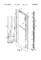
- FIG. 1 is an exploded perspective view of an embodiment of the invention
- FIG. 2 is a perspective view of a structural stud which is attached to opposite faces of the solid core wall panels, and which is used for supporting the wall covering panels;
- FIG. 3 is an enlarged fragmentary perspective view of a lower portion of the structural stud shown in FIG. 2;
- FIG. 4 is an end view of the modular wall system shown in FIG. 1;
- FIG. 5 is an exploded perspective view of the solid core wall panels shown in FIG. 1, showing the manner in which the wall panels are constructured;
- FIG. 6 is a perspective view of the solid core partition wall panel in an assembled state
- FIG. 7 is a fragmentary sectional view along lines VII--VII of FIG. 1;
- FIG. 8 is a perspective view of a partially assembled wall panel system having an expressway channel mounted on an upper portion thereof for routing utilities, such as electrical receptacles and associated conductors;
- FIG. 9 is a fragmentary sectional view along lines IX--IX of FIG. 8, with an electrical receptacle, associated electrical conduit, and expressway cover plates mounted on the wall system;
- FIG. 9A is a transverse cross-sectional view of the wall panel system 10 showing an alternative configuration wherein the optional expressway channel shown in FIG. 9 is omitted;
- FIG. 10 is a perspective view of a partially assembled wall system including horizontal straps or rails connected to adjacent spaced apart vertical structural studs for supporting wall coverings or skins, furniture components, or off-walls;
- FIG. 11 is an enlarged perspective view showing the details of the connection between the horizontal straps or rails and the vertical studs shown in FIG. 10;
- FIG. 12 is a perspective view of an off-wall attached to the wall panel system and extending perpendicularly therefrom;
- FIG. 13 is an enlarged, fragmentary perspective view showing details of the interconnection between the off-wall and the horizontal straps or rails shown in FIG. 12;
- FIG. 14 is an enlarged, fragmentary, exploded perspective view showing details of the mounting system used for connecting the off-wall shown in FIG. 12 to the wall system, and showing the manner in which the mounting system is assembled;
- FIG. 15 is a perspective view of a partially assembled wall panel system utilizing alternative off-wall mounting brackets for connecting an off-wall (shown in Phantom) to the wall panel system;
- FIG. 16 is an enlarged, fragmentary perspective view showing details of the offwall bracket shown in FIG. 15;
- FIG. 17 is a perspective view of the connector attached to the off-wall and engaging the off-wall bracket shown in FIG. 16;
- FIG. 18 is a perspective view of a partially assembled wall panel system having a binder bin attached thereto;
- FIG. 19 is an enlarged, exploded, fragmentary perspective view of the wall system and binder bin shown in FIG. 18, and illustrating the manner in which the binder bin is attached to the wall panel system;
- FIG. 20 is a perspective view of a utility panel incorporated into a wall panel of the wall system
- FIG. 20A is an exploded perspective view showing the manner in which the utility panel is installed on the wall panel shown in FIG. 20;
- FIG. 21 is a fragmentary, horizontal sectional view showing two solid core wall panels interconnected with a post in an L-shaped arrangement
- FIG. 22 is a fragmentary, horizontal sectional view showing three solid core wall panels interconnected with a post in an T-shaped arrangement.
- FIG. 23 is a fragmentary, horizontal sectional view showing four solid core wall panels interconnected with a post in an X-shaped arrangement
- FIG. 1 An exploded perspective view of a wall panel system embodying the invention is shown in FIG. 1 to illustrate the manner in which the wall panel assembly is assembled.
- the wall panel system 10 includes a floor track 21, a top track 22, a ceiling core channel 23, and a plurality of interconnected solid core panels 24.
- the floor track 21 and core channel 23 each include a center channel 21A and 23A respectively, and side channels 21B and 22B respectively disposed on opposite sides of the respective center channels.
- the solid core panels include a top edge which is disposed in central channel 23A of core channel 23, and a bottom edge which is disposed in center channel 21A of floor track 21.
- a plurality of adjustable studs 25 are positioned on opposite sides of the solid core panels 24.
- Studs 25 include leveler feet 26 which fit into the side channels 21B of floor track 21. The leveler feet 26 allow adjustment of each side of the wall system 10 separately so that the skins and any furniture of utility modular supported by the studs 25 can be raised and lowered together. Studs 25 also include a pair of spaced apart sections 27, each having a square transverse cross-sections shape, and each having a pattern of apertures therein. On the faces of the square tube sections 27, the pattern includes three apertures, one being a plus-shaped center aperture 28 and the others being oblong apertures 29 and 30 which are located above and below the plus-shaped center aperture.
- studs 25 do not extend to the ceiling. Instead, an expressway channel 34 is mounted along the upper end of studs 25, and custom cut transom wall covering panels or skins 35 extend between expressway channel 34 and the side channels 22B on side track 22 outboard of the center channel 23A of ceiling core channel 23.
- solid core panels 24 are comprised of drywall (e.g., gypsum) panels 37 and 38 which are bonded together. Panels 37 and 38 are sized and bonded together so that the edges 39 of panel 37 overhang the edges 40 of panel 38 whereby a lip is formed on each of the opposite sides of the solid core panel 24.
- a roll-formed sheet metal edger or core channel 41 is attached to the vertical side edges of the solid core panel 24 to protect and reinforce the edges thereof.
- the inside center flange 42 of edger 41 includes a ridge 43 and an adjacent groove 43'. Ridge 43 and groove 43' are configured to interlock with the ridge and groove of an adjacent interconnected solid core panel to form an interlocking lap joint as shown in FIG. 7. Ridges 43 interlock to provide a rigid assembly that cannot be easily pulled apart. Self drilling screws 44 extend through the joint at ridges 43 to connect adjacently aligned core panels 24.
- Installation of the wall panel system 10 involves anchoring floor track 21 to a floor and anchoring top track 22 to a ceiling in a conventional manner such that the tracks are arranged in an overlapping relationship so as to define a vertical plane in which the wall panel system is to be installed.
- Ceiling core channel 23 is then snap-attached to the top track 22.
- the solid core panels 24 are then installed by inserting the upper edge of each solid core panel 24 into center channel 23A of ceiling core channel 23 and dropping the lower edge of each of the solid core panels 24 into the center channel 21A of floor track 21. Panels 24 are then securely connected together with the self drilling screws 44 (FIG. 7).
- Studs 25 include a plurality of vertically spaced apart pairs of key slots 45 which engage corresponding pre-assembled buttons 45 on core channel 41 to facilitate lay-on installation of studs 25 over the joints formed between connected adjacent panels 24. This key slot and button relationship allows the stud 25 to slide in the vertical direction only.
- Expressway channel 34 can be mounted to studs 25 as shown in FIG. 8, either before or after studs 25 are attached to the interconnected wall panels 24. As can be seen in FIG. 8, stud 25 terminates below the top edge of panels 24, at the lower edge of expressway channel 34. Mounting of expressway channel 34 is generally desired but is optional. Attachment of expressway channel 34 is best understood by comparing FIG. 9 which shows the optional expressway channel 34 installed, and FIG.
- FIG. 9A which shows the finished construction of the wall panel system without the optional expressway channels installed. Also shown in FIG. 9 is attachment of an expressway cover 48 which attaches by clip 49 to outer lower flange 50 of expressway channel 34. A transom clip 51 fits into a slot in the top of expressway channel 34 for engaging a bottom connector 52 on transom skin 53. Conduit or other utilities 54 can be routed along the inside of expressway channel 34. With respect to the alternative configuration shown in FIG. 9A, wherein the optional expressway channel 34 is omitted, a longer transom skin 53' is utilized to close off the space between the ceiling core channel 23 and the top of stud 25.
- a clere story or single panel can be supported on a clere story bracket above the expressway.
- Horizontal rails 46 are attached by screws 55 into side holes 56 and 57 located above and below the plus-shaped apertures 58 on the sides of studs 25.
- Horizontal rails 46 include a regular pattern of apertures including plus-shaped center apertures 28' and oblong apertures 29' and 30', located above and below the plus-shaped aperture respectively.
- the apertures 28', 29' and 30' are spaced 1 inch apart and are horizontally aligned with apertures 28, 29 and 30 on stud 25.
- the apertures 28, 29 and 30 and the apertures 28', 29' and 30' define a continuous horizontal roll of apertures spaced 1 inch apart, except in the center of stud 25 where a single aperture is missing.
- An off-link wall 20' (FIG. 12) is attached to wall panel system 10 by a wall connector 60.
- Wall connector 60 includes an off-module plate 61 (FIGS. 13, 14) and an off-module extrusion 62 attached by hook 63 and screw 64 to horizontal rail 46 at a selected location on link wall 20.
- a second off-module plate 61' and off-module extrusion 62' are attached by hook 63' and screw 64' to a pair of studs 25 at the end of wall 20'.
- a pair of extruded elongate connector clips 65 grip the flared edges 66 of off-module extrusion 62 and 62' to securely connect wall 20' to wall panel system 10. Because off-module plate 61 can be mounted in any of a plurality of different locations corresponding to the uniformly spaced apart sets of apertures on studs 25 and horizontal rail 46, wall 20' can be mounted at generally any location off of wall panel system 10.
- FIGS. 15 and 16 Off-module connection of a zone wall partition frame 66 to a wall panel system 10 is shown in FIGS. 15 and 16.
- a zone wall off-module bracket 67 is configured for mating connection to a connector 67' in a mating connector on zone wall frame 66.
- the illustrated zone wall off-module bracket 67 includes teeth 68 for engaging the center of slots 28' in the horizontal rail 46.
- a second end 69 of the bracket 67 is configured for mating connection to the zone wall frame 66 by engagement of a connector piece 67'.
- the zone wall frame 66 can be connected at multiple heights for stability and can be attached at multiple locations corresponding with the various sets of aperture in rail 46.
- Connector piece 67' is more clearly illustrated in FIG. 17.
- Connector piece 67' includes a base which is attached to the upper edge of the partition frame 66, and includes a pair of upwardly projecting tabs which extend through slots in bracket 67 for connecting partition frame 66 to wall panel system 10.
- Binder bins 70 can be incorporated into wall panel system 10.
- Binder bin brackets 71 are extended vertically between adjacent horizontal rails 46 and are configured to engage rails 46 over the top of skins or wall coverings 31. Bracket 71 includes a vertical row of slots 72.
- Binder bins 70 includes hooks 73 configured to engage selected ones of the vertical slots 72.
- a utility panel 75 (FIGS. 20 and 20A) can be incorporated into the wall system 10.
- a section of drywall panels 37 and 38 is cut away to form an opening 76 in core wall 24.
- Edge channels 77 and 78 are fit along at least the top and bottom edges of the opening 76, and a divider pan 79 is fit into the opening 76 and attached to edge channel 77 and 78.
- a box support channel 80 is secured to studs 25 by stud channel brackets 81.
- a junction box 82 is secured to box support channel 80.
- Junction box 82 includes a receptacle 83 and junction box cover 84.
- Utility panel 75 can be formed in wall panel system 10 facing either direction. Accordingly, adjacent panels 24 can be provided with utility panels 75 which can either both face in the same direction or in opposite directions.
- the core panels 24' in which utility panels 75 are mounted differ from panels 24 in that they are comprised of a core panel 37' and spaced apart wide and narrow panels 38A and 38B on each side of panel 37'.
- the resulting panel 24' has substantially the same transverse cross-sectional shape as panels 24 except that vertical recesses 12A and 12B are provided on opposite sides of the panel 24'.
- conduit can be vertically routed from the floor through recess 12A to utility panel 75, vertically from utility panel 75 to expressway channel 34, or horizontally through cut-outs 14 and 16 in studs 25. Cut-outs 14 and 16 in studs 25 provide on area for installation of optional beltway channels for power and data distribution.
- wall panel systems 10 can be interconnected with posts in an L-shaped arrangement, a T-shaped arrangement, or an X-shaped arrangement.
Abstract
Description
Claims (24)
Priority Applications (1)
| Application Number | Priority Date | Filing Date | Title |
|---|---|---|---|
| US08/763,698 US5870867A (en) | 1996-12-09 | 1996-12-09 | Solid core partition wall |
Applications Claiming Priority (1)
| Application Number | Priority Date | Filing Date | Title |
|---|---|---|---|
| US08/763,698 US5870867A (en) | 1996-12-09 | 1996-12-09 | Solid core partition wall |
Publications (1)
| Publication Number | Publication Date |
|---|---|
| US5870867A true US5870867A (en) | 1999-02-16 |
Family
ID=25068558
Family Applications (1)
| Application Number | Title | Priority Date | Filing Date |
|---|---|---|---|
| US08/763,698 Expired - Fee Related US5870867A (en) | 1996-12-09 | 1996-12-09 | Solid core partition wall |
Country Status (1)
| Country | Link |
|---|---|
| US (1) | US5870867A (en) |
Cited By (45)
| Publication number | Priority date | Publication date | Assignee | Title |
|---|---|---|---|---|
| GB2338252A (en) * | 1998-06-08 | 1999-12-15 | Bpb Plc | Fire-resisting wall |
| US6202381B1 (en) | 1996-06-07 | 2001-03-20 | Herman Miller, Inc. | Method for reconfiguring a wall panel system |
| US6223485B1 (en) | 1996-06-07 | 2001-05-01 | Herman Miller, Inc. | Wall panel system |
| US6295764B1 (en) | 1999-06-04 | 2001-10-02 | Herman Miller, Inc. | Stackable wall panel system |
| US6393782B1 (en) | 1999-06-04 | 2002-05-28 | Herman Miller, Inc. | Stackable wall panel system |
| US20030160009A1 (en) * | 2001-11-01 | 2003-08-28 | Wells Andrew D. | Method and apparatus for retail display of cabinets, countertops and related items |
| US6659295B1 (en) * | 1999-03-26 | 2003-12-09 | L&P Property Management Company | Adjustable shelving/display system |
| US6729085B2 (en) | 2001-02-09 | 2004-05-04 | Herman Miller, Inc. | Wall panel system |
| US6848230B2 (en) | 2002-12-11 | 2005-02-01 | Krueger International, Inc. | Connection arrangement for securing frame members together in a wall system |
| NL1024937C2 (en) * | 2003-12-03 | 2005-06-06 | Unispace A G | Soundproof partition wall and method for mounting such a partition wall. |
| US6945002B2 (en) * | 2000-02-18 | 2005-09-20 | Sergio Zambelli | Reinforcement for prefabricated concrete panels with improved bonding to concrete |
| US20080297015A1 (en) * | 2007-05-30 | 2008-12-04 | Steelcase Inc. | Storage unit back stop and method |
| US20090282759A1 (en) * | 2008-05-14 | 2009-11-19 | Porter William H | Relocatable building wall construction |
| US20100289392A1 (en) * | 2009-05-14 | 2010-11-18 | Jason Deweerd | Reversible wall track system for office furniture |
| US20110296778A1 (en) * | 2010-06-08 | 2011-12-08 | Collins Arlan E | Pre-manufactured utility wall |
| US20120000139A1 (en) * | 2010-06-30 | 2012-01-05 | A & A Sheet Metal Products, Inc. | Wall, roof and building structures |
| US20150020470A1 (en) * | 2010-09-24 | 2015-01-22 | Principle Holdings Limited | Modular walling systems |
| US8950132B2 (en) | 2010-06-08 | 2015-02-10 | Innovative Building Technologies, Llc | Premanufactured structures for constructing buildings |
| US20150082727A1 (en) * | 2013-09-23 | 2015-03-26 | Custom Steel Manufacturing Ltd. | Interlocking Panel Assembly for Modular Building Construction |
| US9027307B2 (en) | 2010-06-08 | 2015-05-12 | Innovative Building Technologies, Llc | Construction system and method for constructing buildings using premanufactured structures |
| US9206600B2 (en) | 2010-05-05 | 2015-12-08 | Allsteel Inc. | Modular wall system |
| USD753943S1 (en) | 2011-06-11 | 2016-04-19 | Dirtt Environmental Solutions, Ltd | Modular wall nesting system |
| USD754991S1 (en) | 2011-12-28 | 2016-05-03 | Dirtt Environmental Solutions, Ltd | Modular wall incorporating recessed, extendable furniture |
| US9493940B2 (en) | 2010-06-08 | 2016-11-15 | Innovative Building Technologies, Llc | Slab construction system and method for constructing multi-story buildings using pre-manufactured structures |
| WO2017156011A1 (en) * | 2016-03-07 | 2017-09-14 | Innovative Building Technologies, Llc | Prefabricated demising wall with external conduit engagement features |
| US9943165B2 (en) | 2016-02-10 | 2018-04-17 | Dirtt Environmental Solutions, Ltd. | Embedded furniture having retractible legs with lighting |
| USRE46929E1 (en) | 2004-08-17 | 2018-07-03 | Dirtt Environmental Solutions, Ltd | Integrated reconfigurable wall system |
| US10041289B2 (en) | 2014-08-30 | 2018-08-07 | Innovative Building Technologies, Llc | Interface between a floor panel and a panel track |
| US10260250B2 (en) | 2014-08-30 | 2019-04-16 | Innovative Building Technologies, Llc | Diaphragm to lateral support coupling in a structure |
| US20190169864A1 (en) * | 2016-07-27 | 2019-06-06 | Form 700 Pty Ltd | Formwork assembly |
| US10323428B2 (en) | 2017-05-12 | 2019-06-18 | Innovative Building Technologies, Llc | Sequence for constructing a building from prefabricated components |
| US10329764B2 (en) | 2014-08-30 | 2019-06-25 | Innovative Building Technologies, Llc | Prefabricated demising and end walls |
| US10364572B2 (en) | 2014-08-30 | 2019-07-30 | Innovative Building Technologies, Llc | Prefabricated wall panel for utility installation |
| US10487493B2 (en) | 2017-05-12 | 2019-11-26 | Innovative Building Technologies, Llc | Building design and construction using prefabricated components |
| US10508442B2 (en) | 2016-03-07 | 2019-12-17 | Innovative Building Technologies, Llc | Floor and ceiling panel for slab-free floor system of a building |
| US10676923B2 (en) | 2016-03-07 | 2020-06-09 | Innovative Building Technologies, Llc | Waterproofing assemblies and prefabricated wall panels including the same |
| US10724228B2 (en) | 2017-05-12 | 2020-07-28 | Innovative Building Technologies, Llc | Building assemblies and methods for constructing a building using pre-assembled floor-ceiling panels and walls |
| US10961710B2 (en) | 2016-03-07 | 2021-03-30 | Innovative Building Technologies, Llc | Pre-assembled wall panel for utility installation |
| US11054148B2 (en) | 2014-08-30 | 2021-07-06 | Innovative Building Technologies, Llc | Heated floor and ceiling panel with a corrugated layer for modular use in buildings |
| US11085184B2 (en) | 2014-02-20 | 2021-08-10 | Dirtt Environmental Solutions Ltd. | Interface for mounting interchangable components |
| US11093087B2 (en) | 2016-06-10 | 2021-08-17 | Dirtt Environmental Solutions Ltd. | Glass substrates with touchscreen technology |
| US11098475B2 (en) | 2017-05-12 | 2021-08-24 | Innovative Building Technologies, Llc | Building system with a diaphragm provided by pre-fabricated floor panels |
| USRE48722E1 (en) | 2004-08-17 | 2021-09-07 | Dirtt Environmental Solutions Ltd. | Integrated reconfigurable wall system |
| US11240922B2 (en) | 2016-06-10 | 2022-02-01 | Dirtt Environmental Solutions Ltd. | Wall system with electronic device mounting assembly |
| US11550178B2 (en) | 2016-07-08 | 2023-01-10 | Dirtt Environmental Solutions Inc. | Low-voltage smart glass |
Citations (53)
| Publication number | Priority date | Publication date | Assignee | Title |
|---|---|---|---|---|
| US2260178A (en) * | 1940-02-05 | 1941-10-21 | Jr Emile S Guignon | Removable panel |
| US3449877A (en) * | 1966-07-11 | 1969-06-17 | Miller Herman Inc | Space divider |
| US3462892A (en) * | 1968-01-22 | 1969-08-26 | Ronald K Meyer | Adapter wall |
| US3733756A (en) * | 1971-02-25 | 1973-05-22 | Loewy R | Modular partition system |
| US3848364A (en) * | 1970-01-02 | 1974-11-19 | Angeles Metal Trim Co | Support structure for shelving |
| US4112648A (en) * | 1976-11-08 | 1978-09-12 | The President Of The Agency Of Industrial Science And Technology | Wall structure of hot fluid chamber |
| US4114333A (en) * | 1977-04-05 | 1978-09-19 | Jones Harold E | Wall panel unit |
| US4120124A (en) * | 1977-06-21 | 1978-10-17 | Hon Industries Inc. | Movable wall assembly |
| US4157638A (en) * | 1977-10-03 | 1979-06-12 | Thermo-Core Building Systems, Inc. | Building panel and utilization thereof |
| US4251968A (en) * | 1978-03-02 | 1981-02-24 | Hauserman, Inc. | Demountable interior partition system, components therefor, and method of making such components |
| US4356672A (en) * | 1980-02-08 | 1982-11-02 | Vaughan Walls, Inc. | Partitioning system |
| US4375010A (en) * | 1980-12-12 | 1983-02-22 | Rosemount Office Systems, Inc. | Panel construction including electrical connectors |
| US4438614A (en) * | 1978-03-02 | 1984-03-27 | Hauserman, Inc. | Demountable interior partition system and components therefor |
| US4478018A (en) * | 1981-07-28 | 1984-10-23 | Holand John F | Thermal break exterior insulated wall framing system |
| US4501101A (en) * | 1982-11-04 | 1985-02-26 | Combined America Industries, Inc. | Fire rated component wall system |
| US4535577A (en) * | 1982-12-15 | 1985-08-20 | Global Upholstery Company Limited | Office panelling system |
| US4555283A (en) * | 1982-05-14 | 1985-11-26 | Linhoff & Thesenfitz Maschinenbau Gmbh | Method of forming a storage tank for bitumen in the liquid state |
| US4559410A (en) * | 1984-02-28 | 1985-12-17 | Kimball International, Inc. | Access panel |
| US4581859A (en) * | 1984-11-01 | 1986-04-15 | Clemco Roll Forming, Inc. | Wall stud for simplified assembly |
| US4610118A (en) * | 1985-01-08 | 1986-09-09 | Hill-Rom Company, Inc. | Medical service column |
| US4612744A (en) * | 1981-08-07 | 1986-09-23 | Shamash Jack E | Method, components, and system for assembling buildings |
| US4631881A (en) * | 1985-04-30 | 1986-12-30 | Vickers Public Limited Company | Office screens and partitions |
| US4757657A (en) * | 1986-06-02 | 1988-07-19 | Architectural Wall Systems, Inc. | Floor-to-ceiling wall system |
| US4841699A (en) * | 1988-04-05 | 1989-06-27 | Haworth, Inc. | Wall panel with accessible interior channels for laying in of cables |
| US4862659A (en) * | 1986-06-06 | 1989-09-05 | Haworth, Inc. | Wall panel with accessible interior channels for laying in of cables |
| US4881352A (en) * | 1987-07-30 | 1989-11-21 | Karl Glockenstein | Wall panel arrangement |
| US4884375A (en) * | 1985-05-16 | 1989-12-05 | Usg Interiors, Inc. | System for mounting furniture on wallboard partitions |
| US4918888A (en) * | 1988-02-29 | 1990-04-24 | Hearthstone Builders, Inc. | Chinking closure system for log structures |
| US4944122A (en) * | 1988-10-04 | 1990-07-31 | Wendt Alan C | Horizontally oriented demountable partition system |
| US5007222A (en) * | 1988-11-14 | 1991-04-16 | Raymond Harry W | Foamed building panel including an internally mounted stud |
| US5038539A (en) * | 1984-09-10 | 1991-08-13 | Herman Miller, Inc. | Work space management system |
| US5056285A (en) * | 1987-07-06 | 1991-10-15 | C.O.M. Cooperativa Operai Mobilieri S.C.R.L. | Partition wall, particularly for offices |
| US5062246A (en) * | 1988-11-16 | 1991-11-05 | Sykes Christopher C | Partition structures and frame elements therefor |
| US5065556A (en) * | 1990-05-15 | 1991-11-19 | Westinghouse Electric Corp. | Space dividing partition system having an electrical raceway |
| US5081808A (en) * | 1989-01-06 | 1992-01-21 | Hamilton Industries, Inc. | Partition with enclosure |
| US5154030A (en) * | 1991-05-20 | 1992-10-13 | Harms John A | Modular office partitioning system |
| US5159793A (en) * | 1989-06-02 | 1992-11-03 | Krueger International Inc. | Wall system |
| US5172530A (en) * | 1990-11-06 | 1992-12-22 | Allsteel Inc. | Sound attenuation panel arrangement with cabling accommodating capability for office furniture space divider systems |
| US5214889A (en) * | 1990-01-18 | 1993-06-01 | Herman Miller, Inc. | Electrified wall panel system |
| US5214890A (en) * | 1991-04-29 | 1993-06-01 | Teknion Furniture Systems | Office panel with lay-in communication cable capability |
| US5227005A (en) * | 1988-04-09 | 1993-07-13 | Eti-Tec Maschinenbau Gmbh | Labelling station for labelling objects, such as bottles |
| US5277006A (en) * | 1991-01-18 | 1994-01-11 | Herman Miller, Inc. | Cable management apparatus |
| US5277005A (en) * | 1992-05-04 | 1994-01-11 | Teknion Furniture Systems | Free-standing partitioning panel |
| US5287675A (en) * | 1991-10-07 | 1994-02-22 | Porta-Fab Corporation | Wall stud assembly |
| US5305567A (en) * | 1990-12-19 | 1994-04-26 | Wittler Waldemar E | Interlocking structural members with edge connectors |
| US5309686A (en) * | 1992-02-19 | 1994-05-10 | Kimball International, Inc. | Work space partition system |
| US5337525A (en) * | 1992-03-06 | 1994-08-16 | Herman Miller, Inc. | Rail system |
| US5357055A (en) * | 1992-10-26 | 1994-10-18 | Sireci Donald J | Electric routing system for modular office partitioning systems |
| US5362923A (en) * | 1991-11-27 | 1994-11-08 | Herman Miller, Inc. | System for distributing and managing cabling within a work space |
| US5377466A (en) * | 1992-05-29 | 1995-01-03 | Haworth, Inc. | Separable post/panel system |
| US5406760A (en) * | 1993-10-15 | 1995-04-18 | Hollanding Inc. | Modular office furniture partition |
| US5433046A (en) * | 1992-07-23 | 1995-07-18 | Steelcase Inc. | Telescoping panel construction |
| US5497589A (en) * | 1994-07-12 | 1996-03-12 | Porter; William H. | Structural insulated panels with metal edges |
-
1996
- 1996-12-09 US US08/763,698 patent/US5870867A/en not_active Expired - Fee Related
Patent Citations (53)
| Publication number | Priority date | Publication date | Assignee | Title |
|---|---|---|---|---|
| US2260178A (en) * | 1940-02-05 | 1941-10-21 | Jr Emile S Guignon | Removable panel |
| US3449877A (en) * | 1966-07-11 | 1969-06-17 | Miller Herman Inc | Space divider |
| US3462892A (en) * | 1968-01-22 | 1969-08-26 | Ronald K Meyer | Adapter wall |
| US3848364A (en) * | 1970-01-02 | 1974-11-19 | Angeles Metal Trim Co | Support structure for shelving |
| US3733756A (en) * | 1971-02-25 | 1973-05-22 | Loewy R | Modular partition system |
| US4112648A (en) * | 1976-11-08 | 1978-09-12 | The President Of The Agency Of Industrial Science And Technology | Wall structure of hot fluid chamber |
| US4114333A (en) * | 1977-04-05 | 1978-09-19 | Jones Harold E | Wall panel unit |
| US4120124A (en) * | 1977-06-21 | 1978-10-17 | Hon Industries Inc. | Movable wall assembly |
| US4157638A (en) * | 1977-10-03 | 1979-06-12 | Thermo-Core Building Systems, Inc. | Building panel and utilization thereof |
| US4438614A (en) * | 1978-03-02 | 1984-03-27 | Hauserman, Inc. | Demountable interior partition system and components therefor |
| US4251968A (en) * | 1978-03-02 | 1981-02-24 | Hauserman, Inc. | Demountable interior partition system, components therefor, and method of making such components |
| US4356672A (en) * | 1980-02-08 | 1982-11-02 | Vaughan Walls, Inc. | Partitioning system |
| US4375010A (en) * | 1980-12-12 | 1983-02-22 | Rosemount Office Systems, Inc. | Panel construction including electrical connectors |
| US4478018A (en) * | 1981-07-28 | 1984-10-23 | Holand John F | Thermal break exterior insulated wall framing system |
| US4612744A (en) * | 1981-08-07 | 1986-09-23 | Shamash Jack E | Method, components, and system for assembling buildings |
| US4555283A (en) * | 1982-05-14 | 1985-11-26 | Linhoff & Thesenfitz Maschinenbau Gmbh | Method of forming a storage tank for bitumen in the liquid state |
| US4501101A (en) * | 1982-11-04 | 1985-02-26 | Combined America Industries, Inc. | Fire rated component wall system |
| US4535577A (en) * | 1982-12-15 | 1985-08-20 | Global Upholstery Company Limited | Office panelling system |
| US4559410A (en) * | 1984-02-28 | 1985-12-17 | Kimball International, Inc. | Access panel |
| US5038539A (en) * | 1984-09-10 | 1991-08-13 | Herman Miller, Inc. | Work space management system |
| US4581859A (en) * | 1984-11-01 | 1986-04-15 | Clemco Roll Forming, Inc. | Wall stud for simplified assembly |
| US4610118A (en) * | 1985-01-08 | 1986-09-09 | Hill-Rom Company, Inc. | Medical service column |
| US4631881A (en) * | 1985-04-30 | 1986-12-30 | Vickers Public Limited Company | Office screens and partitions |
| US4884375A (en) * | 1985-05-16 | 1989-12-05 | Usg Interiors, Inc. | System for mounting furniture on wallboard partitions |
| US4757657A (en) * | 1986-06-02 | 1988-07-19 | Architectural Wall Systems, Inc. | Floor-to-ceiling wall system |
| US4862659A (en) * | 1986-06-06 | 1989-09-05 | Haworth, Inc. | Wall panel with accessible interior channels for laying in of cables |
| US5056285A (en) * | 1987-07-06 | 1991-10-15 | C.O.M. Cooperativa Operai Mobilieri S.C.R.L. | Partition wall, particularly for offices |
| US4881352A (en) * | 1987-07-30 | 1989-11-21 | Karl Glockenstein | Wall panel arrangement |
| US4918888A (en) * | 1988-02-29 | 1990-04-24 | Hearthstone Builders, Inc. | Chinking closure system for log structures |
| US4841699A (en) * | 1988-04-05 | 1989-06-27 | Haworth, Inc. | Wall panel with accessible interior channels for laying in of cables |
| US5227005A (en) * | 1988-04-09 | 1993-07-13 | Eti-Tec Maschinenbau Gmbh | Labelling station for labelling objects, such as bottles |
| US4944122A (en) * | 1988-10-04 | 1990-07-31 | Wendt Alan C | Horizontally oriented demountable partition system |
| US5007222A (en) * | 1988-11-14 | 1991-04-16 | Raymond Harry W | Foamed building panel including an internally mounted stud |
| US5062246A (en) * | 1988-11-16 | 1991-11-05 | Sykes Christopher C | Partition structures and frame elements therefor |
| US5081808A (en) * | 1989-01-06 | 1992-01-21 | Hamilton Industries, Inc. | Partition with enclosure |
| US5159793A (en) * | 1989-06-02 | 1992-11-03 | Krueger International Inc. | Wall system |
| US5214889A (en) * | 1990-01-18 | 1993-06-01 | Herman Miller, Inc. | Electrified wall panel system |
| US5065556A (en) * | 1990-05-15 | 1991-11-19 | Westinghouse Electric Corp. | Space dividing partition system having an electrical raceway |
| US5172530A (en) * | 1990-11-06 | 1992-12-22 | Allsteel Inc. | Sound attenuation panel arrangement with cabling accommodating capability for office furniture space divider systems |
| US5305567A (en) * | 1990-12-19 | 1994-04-26 | Wittler Waldemar E | Interlocking structural members with edge connectors |
| US5277006A (en) * | 1991-01-18 | 1994-01-11 | Herman Miller, Inc. | Cable management apparatus |
| US5214890A (en) * | 1991-04-29 | 1993-06-01 | Teknion Furniture Systems | Office panel with lay-in communication cable capability |
| US5154030A (en) * | 1991-05-20 | 1992-10-13 | Harms John A | Modular office partitioning system |
| US5287675A (en) * | 1991-10-07 | 1994-02-22 | Porta-Fab Corporation | Wall stud assembly |
| US5362923A (en) * | 1991-11-27 | 1994-11-08 | Herman Miller, Inc. | System for distributing and managing cabling within a work space |
| US5309686A (en) * | 1992-02-19 | 1994-05-10 | Kimball International, Inc. | Work space partition system |
| US5337525A (en) * | 1992-03-06 | 1994-08-16 | Herman Miller, Inc. | Rail system |
| US5277005A (en) * | 1992-05-04 | 1994-01-11 | Teknion Furniture Systems | Free-standing partitioning panel |
| US5377466A (en) * | 1992-05-29 | 1995-01-03 | Haworth, Inc. | Separable post/panel system |
| US5433046A (en) * | 1992-07-23 | 1995-07-18 | Steelcase Inc. | Telescoping panel construction |
| US5357055A (en) * | 1992-10-26 | 1994-10-18 | Sireci Donald J | Electric routing system for modular office partitioning systems |
| US5406760A (en) * | 1993-10-15 | 1995-04-18 | Hollanding Inc. | Modular office furniture partition |
| US5497589A (en) * | 1994-07-12 | 1996-03-12 | Porter; William H. | Structural insulated panels with metal edges |
Cited By (83)
| Publication number | Priority date | Publication date | Assignee | Title |
|---|---|---|---|---|
| US6393783B2 (en) | 1996-06-07 | 2002-05-28 | Herman Miller, Inc. | Wall panel |
| US6202381B1 (en) | 1996-06-07 | 2001-03-20 | Herman Miller, Inc. | Method for reconfiguring a wall panel system |
| US6223485B1 (en) | 1996-06-07 | 2001-05-01 | Herman Miller, Inc. | Wall panel system |
| US6301847B1 (en) | 1996-06-07 | 2001-10-16 | Herman Miller, Inc. | Wall panel |
| US6339907B1 (en) | 1996-06-07 | 2002-01-22 | Herman Miller, Inc. | System of wall panels |
| GB2338252A (en) * | 1998-06-08 | 1999-12-15 | Bpb Plc | Fire-resisting wall |
| GB2338252B (en) * | 1998-06-08 | 2002-04-24 | Bpb Plc | Fire-resisting wall |
| US6659295B1 (en) * | 1999-03-26 | 2003-12-09 | L&P Property Management Company | Adjustable shelving/display system |
| US6918499B2 (en) | 1999-03-26 | 2005-07-19 | L&P Property Management Company | Adjustable shelving/display system |
| US20040055514A1 (en) * | 1999-03-26 | 2004-03-25 | L&P Property Management Company | Adjustable shelving/display system |
| US6393782B1 (en) | 1999-06-04 | 2002-05-28 | Herman Miller, Inc. | Stackable wall panel system |
| US6295764B1 (en) | 1999-06-04 | 2001-10-02 | Herman Miller, Inc. | Stackable wall panel system |
| US6945002B2 (en) * | 2000-02-18 | 2005-09-20 | Sergio Zambelli | Reinforcement for prefabricated concrete panels with improved bonding to concrete |
| US6729085B2 (en) | 2001-02-09 | 2004-05-04 | Herman Miller, Inc. | Wall panel system |
| US6820388B2 (en) | 2001-02-09 | 2004-11-23 | Herman Miller, Inc. | Stackable wall panel assembly and connector therefor |
| US20030160009A1 (en) * | 2001-11-01 | 2003-08-28 | Wells Andrew D. | Method and apparatus for retail display of cabinets, countertops and related items |
| US7163109B2 (en) * | 2001-11-01 | 2007-01-16 | Masterbrand Cabinets, Inc. | Method and apparatus for retail display of cabinets, countertops and related items |
| US6848230B2 (en) | 2002-12-11 | 2005-02-01 | Krueger International, Inc. | Connection arrangement for securing frame members together in a wall system |
| US8091301B2 (en) | 2003-12-03 | 2012-01-10 | Unispace A.G. | Sound-insulating partition wall and assembly method for such a partition wall |
| NL1024937C2 (en) * | 2003-12-03 | 2005-06-06 | Unispace A G | Soundproof partition wall and method for mounting such a partition wall. |
| EP1538272A1 (en) * | 2003-12-03 | 2005-06-08 | Unispace A.G. | Sound-insulating partition wall and assembly method for such a partition wall |
| US20050188641A1 (en) * | 2003-12-03 | 2005-09-01 | Unispace A.G. | Sound-insulating partition wall and assembly method for such a partition wall |
| USRE48722E1 (en) | 2004-08-17 | 2021-09-07 | Dirtt Environmental Solutions Ltd. | Integrated reconfigurable wall system |
| USRE47132E1 (en) | 2004-08-17 | 2018-11-20 | Dirtt Environmental Solutions, Ltd | Integrated reconfigurable wall system |
| USRE46929E1 (en) | 2004-08-17 | 2018-07-03 | Dirtt Environmental Solutions, Ltd | Integrated reconfigurable wall system |
| USRE47693E1 (en) | 2004-08-17 | 2019-11-05 | Dirtt Environmental Solutions, Ltd. | Integrated reconfigurable wall system |
| US20080297015A1 (en) * | 2007-05-30 | 2008-12-04 | Steelcase Inc. | Storage unit back stop and method |
| US20080296457A1 (en) * | 2007-05-30 | 2008-12-04 | Steelcase Inc. | Furniture storage unit and method |
| US8104850B2 (en) | 2007-05-30 | 2012-01-31 | Steelcase Inc. | Furniture storage unit |
| US20090282759A1 (en) * | 2008-05-14 | 2009-11-19 | Porter William H | Relocatable building wall construction |
| US8128182B2 (en) | 2009-05-14 | 2012-03-06 | Haworth, Inc. | Reversible wall track system for office furniture |
| US20100289392A1 (en) * | 2009-05-14 | 2010-11-18 | Jason Deweerd | Reversible wall track system for office furniture |
| US9284729B2 (en) | 2010-05-05 | 2016-03-15 | Allsteel Inc. | Modular wall system |
| US9765518B2 (en) | 2010-05-05 | 2017-09-19 | Allsteel Inc. | Modular wall system |
| US11725382B2 (en) | 2010-05-05 | 2023-08-15 | Allsteel Inc. | Modular wall system |
| US10309102B2 (en) | 2010-05-05 | 2019-06-04 | Allsteel, Inc. | Modular wall system |
| US10927545B2 (en) | 2010-05-05 | 2021-02-23 | Allsteel Inc. | Modular wall system |
| US9206600B2 (en) | 2010-05-05 | 2015-12-08 | Allsteel Inc. | Modular wall system |
| US9027307B2 (en) | 2010-06-08 | 2015-05-12 | Innovative Building Technologies, Llc | Construction system and method for constructing buildings using premanufactured structures |
| US20110296778A1 (en) * | 2010-06-08 | 2011-12-08 | Collins Arlan E | Pre-manufactured utility wall |
| US9382709B2 (en) | 2010-06-08 | 2016-07-05 | Innovative Building Technologies, Llc | Premanufactured structures for constructing buildings |
| US9493940B2 (en) | 2010-06-08 | 2016-11-15 | Innovative Building Technologies, Llc | Slab construction system and method for constructing multi-story buildings using pre-manufactured structures |
| US8978324B2 (en) | 2010-06-08 | 2015-03-17 | Innovative Building Technologies, Llc | Pre-manufactured utility wall |
| US10190309B2 (en) | 2010-06-08 | 2019-01-29 | Innovative Building Technologies, Llc | Slab construction system and method for constructing multi-story buildings using pre-manufactured structures |
| US8950132B2 (en) | 2010-06-08 | 2015-02-10 | Innovative Building Technologies, Llc | Premanufactured structures for constructing buildings |
| US10145103B2 (en) | 2010-06-08 | 2018-12-04 | Innovative Building Technologies, Llc | Premanufactured structures for constructing buildings |
| US8677708B2 (en) * | 2010-06-30 | 2014-03-25 | A&A Sheet Metal Products, Inc. | Wall, roof and building structures |
| US20120000139A1 (en) * | 2010-06-30 | 2012-01-05 | A & A Sheet Metal Products, Inc. | Wall, roof and building structures |
| US20150020470A1 (en) * | 2010-09-24 | 2015-01-22 | Principle Holdings Limited | Modular walling systems |
| US9347218B2 (en) | 2011-06-11 | 2016-05-24 | Dirtt Environmental Solutions, Ltd. | Modular wall nesting system |
| USD753943S1 (en) | 2011-06-11 | 2016-04-19 | Dirtt Environmental Solutions, Ltd | Modular wall nesting system |
| US10920418B2 (en) | 2011-12-28 | 2021-02-16 | Dirtt Environmental Solutions, Ltd | Modular walls incorporating recessed, extendable furniture |
| USD754991S1 (en) | 2011-12-28 | 2016-05-03 | Dirtt Environmental Solutions, Ltd | Modular wall incorporating recessed, extendable furniture |
| US9181712B2 (en) * | 2013-09-23 | 2015-11-10 | Custom Steel Manufacturing, Ltd. | Interlocking panel assembly for modular building construction |
| US20150082727A1 (en) * | 2013-09-23 | 2015-03-26 | Custom Steel Manufacturing Ltd. | Interlocking Panel Assembly for Modular Building Construction |
| US11085184B2 (en) | 2014-02-20 | 2021-08-10 | Dirtt Environmental Solutions Ltd. | Interface for mounting interchangable components |
| US10329764B2 (en) | 2014-08-30 | 2019-06-25 | Innovative Building Technologies, Llc | Prefabricated demising and end walls |
| US11054148B2 (en) | 2014-08-30 | 2021-07-06 | Innovative Building Technologies, Llc | Heated floor and ceiling panel with a corrugated layer for modular use in buildings |
| US10975590B2 (en) | 2014-08-30 | 2021-04-13 | Innovative Building Technologies, Llc | Diaphragm to lateral support coupling in a structure |
| US11060286B2 (en) | 2014-08-30 | 2021-07-13 | Innovative Building Technologies, Llc | Prefabricated wall panel for utility installation |
| US10364572B2 (en) | 2014-08-30 | 2019-07-30 | Innovative Building Technologies, Llc | Prefabricated wall panel for utility installation |
| US10260250B2 (en) | 2014-08-30 | 2019-04-16 | Innovative Building Technologies, Llc | Diaphragm to lateral support coupling in a structure |
| US10041289B2 (en) | 2014-08-30 | 2018-08-07 | Innovative Building Technologies, Llc | Interface between a floor panel and a panel track |
| US9943165B2 (en) | 2016-02-10 | 2018-04-17 | Dirtt Environmental Solutions, Ltd. | Embedded furniture having retractible legs with lighting |
| US10058170B2 (en) | 2016-02-10 | 2018-08-28 | Dirtt Environmental Solutions, Ltd | Modular walls with embedded furniture and opposing feature |
| US10508442B2 (en) | 2016-03-07 | 2019-12-17 | Innovative Building Technologies, Llc | Floor and ceiling panel for slab-free floor system of a building |
| US10961710B2 (en) | 2016-03-07 | 2021-03-30 | Innovative Building Technologies, Llc | Pre-assembled wall panel for utility installation |
| JP2019507835A (en) * | 2016-03-07 | 2019-03-22 | イノベイティブ ビルディング テクノロジーズ,エルエルシー | Prefabricated partition wall with external conduit engagement features |
| KR102195715B1 (en) | 2016-03-07 | 2020-12-29 | 이노베이티브 빌딩 테크놀러지스 엘엘씨 | Prefabricated dimming wall with exterior conduit engagement features |
| US10900224B2 (en) | 2016-03-07 | 2021-01-26 | Innovative Building Technologies, Llc | Prefabricated demising wall with external conduit engagement features |
| US10676923B2 (en) | 2016-03-07 | 2020-06-09 | Innovative Building Technologies, Llc | Waterproofing assemblies and prefabricated wall panels including the same |
| AU2017229468B2 (en) * | 2016-03-07 | 2019-10-24 | Innovative Building Technologies, Llc | Prefabricated demising wall with external conduit engagement features |
| WO2017156011A1 (en) * | 2016-03-07 | 2017-09-14 | Innovative Building Technologies, Llc | Prefabricated demising wall with external conduit engagement features |
| KR20180117137A (en) * | 2016-03-07 | 2018-10-26 | 이노베이티브 빌딩 테크놀러지스 엘엘씨 | Prefabricated deminging wall with exterior conduit engagement features |
| US11093087B2 (en) | 2016-06-10 | 2021-08-17 | Dirtt Environmental Solutions Ltd. | Glass substrates with touchscreen technology |
| US11240922B2 (en) | 2016-06-10 | 2022-02-01 | Dirtt Environmental Solutions Ltd. | Wall system with electronic device mounting assembly |
| US11550178B2 (en) | 2016-07-08 | 2023-01-10 | Dirtt Environmental Solutions Inc. | Low-voltage smart glass |
| US20190169864A1 (en) * | 2016-07-27 | 2019-06-06 | Form 700 Pty Ltd | Formwork assembly |
| US10808411B2 (en) * | 2016-07-27 | 2020-10-20 | Form 700 Pty Ltd | Formwork assembly with interlocking side frame members |
| US10323428B2 (en) | 2017-05-12 | 2019-06-18 | Innovative Building Technologies, Llc | Sequence for constructing a building from prefabricated components |
| US11098475B2 (en) | 2017-05-12 | 2021-08-24 | Innovative Building Technologies, Llc | Building system with a diaphragm provided by pre-fabricated floor panels |
| US10724228B2 (en) | 2017-05-12 | 2020-07-28 | Innovative Building Technologies, Llc | Building assemblies and methods for constructing a building using pre-assembled floor-ceiling panels and walls |
| US10487493B2 (en) | 2017-05-12 | 2019-11-26 | Innovative Building Technologies, Llc | Building design and construction using prefabricated components |
Similar Documents
| Publication | Publication Date | Title |
|---|---|---|
| US5870867A (en) | Solid core partition wall | |
| US5822935A (en) | Solid-core wall system | |
| US6128877A (en) | Variable width end panel | |
| US6047508A (en) | Wall panel partition system | |
| US9650785B2 (en) | Reusable architectural wall | |
| US6141925A (en) | Clear wall panel system | |
| US4120124A (en) | Movable wall assembly | |
| US6658805B1 (en) | Panel arrangement | |
| US5086597A (en) | Work space management system hallway wall arrangement | |
| US5644877A (en) | Demountable ceiling closure | |
| US4571906A (en) | Sectional screens | |
| US5930960A (en) | Prefab wall element with integrated chases | |
| US5038534A (en) | Unitary panel module and connector | |
| US6230459B1 (en) | Wall start for panel systems | |
| US4910938A (en) | Wall stud for portable/in-plant building | |
| US4080766A (en) | Demountable partition structure | |
| US20090056249A1 (en) | Modular space dividing system | |
| US6345478B1 (en) | Method of partitioning office spaces | |
| US6170211B1 (en) | Demountable wall system | |
| US4713920A (en) | Modular tongue and groove removable panel partition system | |
| GB2346905A (en) | Framework for office partition | |
| JP3123701B2 (en) | Office structure | |
| JPH017776Y2 (en) | ||
| CA2811350C (en) | Load supporting blocking member for use in a metal stud wall | |
| EP0214378A1 (en) | Internal enclosure |
Legal Events
| Date | Code | Title | Description |
|---|---|---|---|
| AS | Assignment |
Owner name: STEELCASE, INC., MICHIGAN Free format text: ASSIGNMENT OF ASSIGNORS INTEREST;ASSIGNOR:MITCHELL, TERRY;REEL/FRAME:008347/0725 Effective date: 19961118 |
|
| AS | Assignment |
Owner name: STEELCASE DEVELOPMENT INC., A CORPORATION OF MICHI Free format text: ASSIGNMENT OF ASSIGNORS INTEREST;ASSIGNOR:STEELCASE INC., A CORPORATION OF MICHIGAN;REEL/FRAME:010188/0385 Effective date: 19990701 |
|
| CC | Certificate of correction | ||
| FEPP | Fee payment procedure |
Free format text: PAYOR NUMBER ASSIGNED (ORIGINAL EVENT CODE: ASPN); ENTITY STATUS OF PATENT OWNER: LARGE ENTITY |
|
| FPAY | Fee payment |
Year of fee payment: 4 |
|
| FPAY | Fee payment |
Year of fee payment: 8 |
|
| FEPP | Fee payment procedure |
Free format text: PAYOR NUMBER ASSIGNED (ORIGINAL EVENT CODE: ASPN); ENTITY STATUS OF PATENT OWNER: LARGE ENTITY Free format text: PAYER NUMBER DE-ASSIGNED (ORIGINAL EVENT CODE: RMPN); ENTITY STATUS OF PATENT OWNER: LARGE ENTITY |
|
| REMI | Maintenance fee reminder mailed | ||
| LAPS | Lapse for failure to pay maintenance fees | ||
| STCH | Information on status: patent discontinuation |
Free format text: PATENT EXPIRED DUE TO NONPAYMENT OF MAINTENANCE FEES UNDER 37 CFR 1.362 |
|
| FP | Lapsed due to failure to pay maintenance fee |
Effective date: 20110216 |