JP2005102737A - Freely expanded desk - Google Patents

Freely expanded desk Download PDF

Info

Publication number
JP2005102737A
JP2005102737A JP2003336423A JP2003336423A JP2005102737A JP 2005102737 A JP2005102737 A JP 2005102737A JP 2003336423 A JP2003336423 A JP 2003336423A JP 2003336423 A JP2003336423 A JP 2003336423A JP 2005102737 A JP2005102737 A JP 2005102737A
Authority
JP
Japan
Prior art keywords
top plate
core body
wiring
wiring core
desk
Prior art date
Legal status (The legal status is an assumption and is not a legal conclusion. Google has not performed a legal analysis and makes no representation as to the accuracy of the status listed.)
Granted
Application number
JP2003336423A
Other languages
Japanese (ja)
Other versions
JP4307200B2 (en
Inventor
Takeshi Shiratori
毅 白鳥
Junichi Okubo
純一 大久保
Current Assignee (The listed assignees may be inaccurate. Google has not performed a legal analysis and makes no representation or warranty as to the accuracy of the list.)
Itoki Co Ltd
Itoki All Steel Co Ltd
Original Assignee
Itoki Co Ltd
Itoki All Steel Co Ltd
Priority date (The priority date is an assumption and is not a legal conclusion. Google has not performed a legal analysis and makes no representation as to the accuracy of the date listed.)
Filing date
Publication date
Application filed by Itoki Co Ltd, Itoki All Steel Co Ltd filed Critical Itoki Co Ltd
Priority to JP2003336423A priority Critical patent/JP4307200B2/en
Publication of JP2005102737A publication Critical patent/JP2005102737A/en
Application granted granted Critical
Publication of JP4307200B2 publication Critical patent/JP4307200B2/en
Anticipated expiration legal-status Critical
Expired - Fee Related legal-status Critical Current

Links

Images

Abstract

<P>PROBLEM TO BE SOLVED: To provide a freely expanded desk having a systematic and free expanding property of the desk by a further flexible mode and greatly simplifying a joining structure therefor. <P>SOLUTION: This freely expanded desk is formed into a laterally long groove shape having left/right side walls 1 and 2, front/rear walls 3 and 4 and an opened upper face; is formed with a wiring core body BC of a laterally long groove shape having self-supporting leg parts 5 on the both left/right sides and having the inside of the groove as a wiring space; and the wiring core body BC and top plate support members 6 and 7 connected to the front face, the rear face or the front/rear faces of the wiring core body is made to support at least one top plate selected from top plates 8-12 with different lengths. <P>COPYRIGHT: (C)2005,JPO&NCIPI

Description

本発明は、様々な形状並びに形態の天板を選択的に組込むことができると共に、様々な形態,機能を有するオプションパーツの選択的装着を可能にすることにより、オフィスにおける多様なデスク形態、或は、ワークステーション形態などに容易かつ迅速に自在かつシステマティックな展開を可能にするデスクに関する。   The present invention can selectively incorporate various shapes and forms of top plates, and enables selective mounting of optional parts having various forms and functions, thereby allowing various desk forms in the office, or Relates to a desk that allows easy and quick flexible and systematic deployment in a workstation form or the like.

従来より様々な形態に展開できるデスクは、特許文献1〜3などにより公知である。これらのデスクは、様々な形態に展開可能であることを実現するために、夫々に独自の工夫が施されたものであるが、未だ解決すべき問題も包含したものである。   Conventionally, desks that can be developed in various forms are known from Patent Documents 1-3. These desks are each independently devised in order to realize that they can be developed in various forms, but still include problems to be solved.

即ち、上記の公知デスクに共通する難点は、展開形態に柔軟性が乏しいこと、並びに、概して展開のための接合構造が複雑になりがちな点などにある。
特開昭61−137944号公報 特公昭61−37419号公報 特開昭2003−204827号公報
That is, the common problems of the above-mentioned known desks are that the deployment form is inflexible and that the joint structure for deployment generally tends to be complicated.
JP-A 61-137944 Japanese Patent Publication No. 61-37419 JP-A-2003-204827

そこで本発明では、デスクのシステマティックで自在な展開性をより柔軟な態様で拡張できると共に、そのための接合構造を大幅に簡素化した自在な展開ができるようにしたデスクを提供することを課題とするものである。   Accordingly, an object of the present invention is to provide a desk that can expand the systematic and freely deployable nature of the desk in a more flexible manner, and can be freely deployed with a greatly simplified joint structure. Is.

上記課題を解決することを目的としてなされた本発明デスクの第一の構成は、左右側壁と前後壁を具備して上面を開放した横長溝状に形成し、かつ、左右両側に自立用脚部を設けた横長溝型状で溝内部を配線スペースとする配線コア体を形成し、該配線コア体とその前面又は後面若しくは前後面に結合した天板支持部材に、長さが異なる天板の中から選択した少なくとも1枚の天板を支持させたことを特徴とするものである。   The first configuration of the desk of the present invention, which has been made for the purpose of solving the above-mentioned problems, is formed in a horizontally long groove shape having left and right side walls and front and rear walls and having an open top surface, and has legs for self-supporting on both left and right sides. Forming a wiring core body with a wiring space inside the groove, and a top plate support member coupled to the front surface, the rear surface, or the front and rear surfaces of the wiring core body, It is characterized by supporting at least one top plate selected from the inside.

ここで、配線コア体は、夫々下面に自立用脚部が取り付けられる所要厚みを有する左右側壁と該左右側壁に結合される前後壁とを、平面視横長矩形状をなすように結合したものである。   Here, the wiring core body is obtained by joining right and left side walls having a required thickness to which the legs for self-supporting are attached to the lower surface and front and rear walls joined to the left and right side walls so as to form a horizontally long rectangular shape in plan view. is there.

また、配線コア体の前面と後面は前後と左右側壁の外面が形成し、これらの外面はその長さ方向に沿った溝を有し、該溝を天板支持部材などの結合部として用いられるように形成されている。   Further, the front and rear surfaces of the wiring core body are formed with front and rear and outer surfaces of the left and right side walls, and these outer surfaces have grooves along the length direction, and the grooves are used as coupling parts such as a top plate support member. It is formed as follows.

上記本発明デスクの天板支持部材は、配線コア体の前後面の溝に結合される壁結合部と、天板奥行方向で少なくとも所定の間隔を有する少なくとも2箇所の天板結合部と、2箇所の天板結合部を連結した連結部と、該連結部の中間部分から下方へ延設された脚部とから成る天板支持脚部材か、又は、配線コア体の前後面の溝に結合される壁結合部と、該結合部から天板裏面側に延設され当該天板の裏面に結合される天板結合部とから成る側面視大略「状に形成した天板支持腕部材である。   The top plate support member of the desk of the present invention includes a wall joint portion coupled to the front and rear grooves of the wiring core body, at least two top plate joint portions having at least a predetermined interval in the top plate depth direction, and 2 Connected to the top plate support leg member consisting of a connecting portion connecting the top plate connecting portions of the places and a leg portion extending downward from the intermediate portion of the connecting portion, or a groove on the front and rear surfaces of the wiring core body A top plate support arm member formed in a generally “shape” in a side view comprising a wall coupling portion and a top plate coupling portion extending from the coupling portion to the back surface side of the top plate and coupled to the back surface of the top plate. .

また、配線コア体自体がなす溝の両端部には、上部フレーム用の支柱部材を結合させて立て、左右の支柱部材に上部梁部材を架設して上部フレームを形成し、当該梁部材に、オーバーヘッド型のキャビネット,液晶等による平板状のモニタ,シェルフ用の棚板,モニタなどを載せる小天板などのオプションパーツを、選択的かつ着脱自在に架装できるようにした。従って、配線コア体の前後壁の少なくとも内面には、前記オプションパーツを架装するための接合部を簡素化するため、長さ方向に沿って少なくとも1本の凹溝、又は、凸条を形成する。   In addition, at both ends of the groove formed by the wiring core body itself, a column member for the upper frame is joined and stands, and the upper beam member is installed on the left and right column members to form the upper frame. Optional parts such as overhead cabinets, flat-panel monitors made of liquid crystal, shelves for shelves, small top boards for mounting monitors, etc., can now be selectively and detachably mounted. Accordingly, at least one concave groove or ridge is formed along the length direction on at least the inner surfaces of the front and rear walls of the wiring core body in order to simplify the joint for mounting the optional parts. To do.

更に、本発明デスクでは、上部フレームに代えて或は上部フレームと併用して、配線コア体の前後壁による溝部に、その長さ方向に移動可能にして門型フレーム部材を立設したり、或は、配線コア体の前後壁による溝部に配線用のトレーを架設したり、また、配線コア体の下に配線ダクトや幕板などを吊下して設けることができる。   Furthermore, in the desk of the present invention, instead of the upper frame or in combination with the upper frame, the gate-type frame member can be erected in the groove portion by the front and rear walls of the wiring core body so as to be movable in the length direction, Alternatively, a wiring tray can be installed in a groove formed by the front and rear walls of the wiring core body, or a wiring duct, a curtain plate, etc. can be suspended below the wiring core body.

一方、上記本発明デスクにおける配線コア体の上方側には、そのコア体の前後壁に支持させて当該コア体と一体化される固定型のパネルや一部分の組立,分解を可能にしたブロック型のパネル、或は、配線コア体の長さ方向に移動可能な移動型のパネルを設置することができる。   On the other hand, on the upper side of the wiring core body in the desk of the present invention, a fixed panel that is supported by the front and rear walls of the core body and integrated with the core body, and a block type that enables assembling and disassembling a part thereof A movable panel that can move in the length direction of the wiring core body can be installed.

本発明デスクにおいては、配線コア体の長さは、一例として、1200mmから200mm刻みで1800mmまで、そしてロングタイプとして2400mmのものがある。従って、配線コア体に結合して取付けられるデスク用天板のうち主天板は、前記コア体に結合される長辺及び/又は当該長辺と直角に交わる短辺の長さが、前記コア体の各長さである1200mm〜1800mm、或は、2400mmに見合う長さのもの、或は、短辺の長さが配線コア体の前記各長さの整数分の一の長さのものが使用されることにより、システマティックな複合形のデスクを自在に展開できる。   In the desk of the present invention, the length of the wiring core body is, for example, 1200 mm to 1800 mm in 200 mm increments, and 2400 mm as the long type. Therefore, the main top plate of the desk top plate coupled to the wiring core body has a long side coupled to the core body and / or a length of a short side perpendicular to the long side. The length corresponding to each body length of 1200 mm to 1800 mm or 2400 mm, or the length of the short side is an integral fraction of the length of each of the wiring core bodies. By using it, a systematic composite desk can be developed freely.

これらのサイズ違いの主天板では、典型的な長方形から手前側の辺の一部を凹状に弯曲させたもの(或は、逆に凸状に弯曲させたもの)まで種々の形態のものがある。そして、前記主天板は、その長辺又は短辺の長さを選択すると共に、選択した天板の長辺又は短辺を配線コア体に天板支持部材を介して結合することにより、天板の向きを変えた態様での配設を実現する。   These main top plates of different sizes come in various forms, from typical rectangles to those in which a part of the front side is bent into a concave shape (or conversely bent into a convex shape). is there. The main top plate selects the length of the long side or short side, and connects the long side or short side of the selected top plate to the wiring core body via the top plate support member. Arrangement in a manner in which the direction of the plate is changed is realized.

本発明デスクに用いる天板には、上記主天板のほかその主天板を補完したり、ミーティング用の小天板空間を形成する、或は、主天板上を広く使用するためモニタを載せるためのモニタ用小天板など、補助的役割の補助天板がある。本発明における上記の各天板は、前記配線コア体における前後面に結合される天板支持脚部材又は天板支持腕部材に支持されることにより、配線コア体に結合されて各天板がデスクを形成する。なお、天板支持腕部材を介して配線コア体に結合される主天板及び補助天板は、その手前側に柱状のサポート用支脚を備えたものがある。   In addition to the main top plate, the top plate used for the desk of the present invention complements the main top plate, forms a small top plate space for meetings, or a monitor for wide use on the main top plate. There is an auxiliary top plate that plays an auxiliary role, such as a small top plate for monitoring. Each top plate according to the present invention is coupled to the wiring core body by being supported by a top plate support leg member or a top plate support arm member coupled to the front and rear surfaces of the wiring core body. Form a desk. Some main top boards and auxiliary top boards that are coupled to the wiring core body via the top board support arm members are provided with columnar support legs on the front side thereof.

本発明デスクでは、左右側壁と前後壁を具備して上面を開放した横長溝状に形成し、かつ、左右両側に自立用脚部を設けた横長溝型状で溝内部を配線スペースとする配線コア体を形成し、この配線コア体の一つ、又はこれを連結したものに、種々のサイズ,形態の天板をその長辺又は短辺において近接させて配置すると共に、その天板を天板支持脚部材又は天板支持腕部材を選択的に用いて取付けることにより、同じ天板或は異なる天板を組合せた複数かつ複合形のデスクを展開できるようにしたので、従来の展開形のデスクに比べより拡張された形態の複合形デスクを容易かつ迅速に展開することができる。   In the desk according to the present invention, a laterally elongated groove shape having left and right side walls and front and rear walls and having an open upper surface, and having a self-supporting leg portion on both the left and right sides, and wiring inside the groove as a wiring space A core body is formed, and a top plate of various sizes and forms is arranged close to one of the wiring core bodies or the connected core body in the long side or the short side, and the top plate is placed on the top. By selectively using the plate support leg member or the top plate support arm member, a plurality of composite desks combining the same top plate or different top plates can be developed. It is possible to easily and quickly deploy a composite desk having a more expanded form than a desk.

次に本発明デスクについて、様々な形態のデスクを形成するための核となる配線コア体の構成と、この配線コア体に取付けられてデスクを構成するための様々なパーツや部材との関係について、図を参照して説明する。   Next, regarding the desk of the present invention, the configuration of the wiring core body that is the core for forming various types of desks, and the relationship between various parts and members that are attached to the wiring core body and constitute the desk This will be described with reference to the drawings.

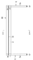
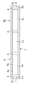
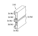
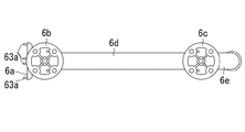
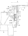
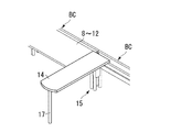
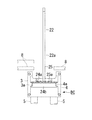
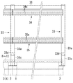
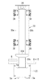
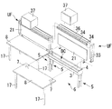
図1は本発明デスクにおける配線コア体の一例の斜視図、図2は図1の配線コア体の正面図、図3は図2の配線コア体の平面図、図4は図1の配線コア体の右側面図、図5は図1の配線コア体のA−A矢視断面図、図6は図1の配線コア体の左右側壁の一例として用いる側壁ブロックの形態を例示した斜視図、図7は配線コア体の前後壁の一例として用いる壁状梁部材の断面形状を例示した斜視図、図8は図1〜図5の配線コア体に取付けられる天板支持脚部材の側面図、図9は図8の天板支持脚部材の左側面図、図10は図8の天板支持脚部材の平面図、図11は連結した配線コア体に取付けた図8〜図10の天板支持脚部材の斜視図、図12は図1〜図5の配線コア体に取付けられる短い方の天板支持腕部材の例の側断面図、図13は図12の支持腕部材の高さを変更した側面図、図14は長い方の天板支持腕部材の例の長さを省略した要部の側断面図、図15は図14の天板支持腕部材を連結した配線コア体に取付けた状態の斜視図、図16は図1〜図5の配線コア体と図8〜図10の天板支持脚部材と主天板を用いて構成した本発明デスクの第一例の側断面図、図17は図16の本発明デスクの斜視図、図18は図1〜図5の配線コア体と図12の短い方の天板支持腕部材と主天板を用いて構成した本発明デスクの第二例の側断面図、図19は様々な平面形状の主天板を用いて形成した複数体の本発明デスクをレイアウトした例を示す平面図、図20は本発明デスクで使用される補助天板の第一例の斜視図、図21は本発明デスクで使用される補助天板の第二例の斜視図、図22は本発明デスクで使用される補助天板の第三例の斜視図、図23は本発明デスクで使用される補助天板の第四例の斜視図、図24は配線コア体の前後壁の溝に架装される移動可能な略門型をなす移動フレームの一例の斜視図、図25は配線コア体の前後壁の溝に吊設される配線ダクトの一例の斜視図、図26は配線ダクトの取付構造例の要部の断面図、図27は配線コア体の下部に設けられる幕板の一例の斜視図、図28は幕板の取付構造例の要部の断面図、図29は配線コア体に立設した固定パネルの斜視図、図30は配線コア体に立設した下部が分解できる固定パネルの斜視図、図31は配線コア体に立設した移動できるパネルの斜視図、図32は図30のパネルの構成を説明するための長さ方向の中間を省略した正面図、図33は図32のパネルの側面図、図34はパネルの立設構造の要部を示す断面図、図35は図30,図32のパネルの下半部の着脱構造を説明するための要部を示す正面図、図36は図30,図32のパネルの下半部の着脱構造を説明するための要部を示す断面図、図37は図30,図32のパネルの下半部の着脱構造を説明するための要部を示す断面図、図38は図30,図32のパネルの下半部を取外して配線コンセントなどの投込みができる状態を説明するための斜視図、図39は図30,図32のパネルの下半部にコンセントボックスを取付けた状態の斜視図、図40は配線コア体の上に設けるパネル付120度扇形補助天板の斜視図、図41は遮蔽パネル付扇形天板を主天板に拡張して配線コア体に取付けて形成した本発明デスクの例の平面図、図42は配線コア体の上方に立設される上部フレームの例の斜視図、図43は図42の上部フレームの長さ方向中間を省略した要部の正面図、図44は図42の上部フレームの側面図、図45は上部フレームに架装したオーバーヘッドキャビネットの例を示す斜視図、図46はオーバキャビネットの取付構造例を示す要部の断面図、図47は上部フレームに架装した液晶モニタの例の斜視図、図48は配線コア体に天板と適宜のオプションパーツを選択して取付け本発明デスクに展開する一例を示す斜視図、図49は配線コア体に天板と適宜のオプションパーツを選択して取付け本発明デスクに展開する別の例を示す斜視図、図50は配線コア体に天板を選択して取付け本発明デスクに展開する例を示す斜視図、図51は連結した配線コア体に、天板と様々なオプションパーツを選択して取付け目的に応じた本発明デスクを展開する第一例を示す斜視図、図52は連結した配線コア体に、天板と様々なオプションパーツを選択して取付け目的に応じた本発明デスクを展開する第二例を示す斜視図、図53は連結した配線コア体に、天板と様々なオプションパーツを選択して取付け目的に応じた本発明デスクを展開する第三例を示す斜視図、図54は連結した配線コア体に、天板と様々なオプションパーツを選択して取付け目的に応じた本発明デスクを展開する第四例を示す斜視図、図55は連結した配線コア体に、天板と様々なオプションパーツを選択して取付け目的に応じた本発明デスクを展開する第五例を示す斜視図、図56は連結した配線コア体に、天板と様々なオプションパーツを選択して取付け目的に応じた本発明デスクを展開する第六例を示す斜視図である。   1 is a perspective view of an example of a wiring core body in the desk of the present invention, FIG. 2 is a front view of the wiring core body of FIG. 1, FIG. 3 is a plan view of the wiring core body of FIG. FIG. 5 is a cross-sectional view taken along line AA of the wiring core body of FIG. 1, and FIG. 6 is a perspective view illustrating the form of a side wall block used as an example of the left and right side walls of the wiring core body of FIG. 7 is a perspective view illustrating a cross-sectional shape of a wall-like beam member used as an example of the front and rear walls of the wiring core body, FIG. 8 is a side view of a top plate support leg member attached to the wiring core body of FIGS. 9 is a left side view of the top plate support leg member of FIG. 8, FIG. 10 is a plan view of the top plate support leg member of FIG. 8, and FIG. 11 is a top plate of FIGS. 12 is a perspective view of a support leg member, FIG. 12 is a side sectional view of an example of a shorter top plate support arm member attached to the wiring core body of FIGS. 1 to 5, and FIG. 13 is a support arm member of FIG. FIG. 14 is a side sectional view of a main part in which the length of the example of the longer top plate support arm member is omitted, and FIG. 15 is a wiring core in which the top plate support arm members of FIG. 14 are connected. FIG. 16 is a perspective view of the first embodiment of the desk of the present invention configured using the wiring core body of FIGS. 1 to 5, the top plate support leg members of FIGS. 8 to 10 and the main top plate. FIG. 17 is a perspective view of the desk of the present invention shown in FIG. 16, and FIG. 18 is constructed using the wiring core body shown in FIGS. 1 to 5, the shorter top plate supporting arm member and the main top plate shown in FIG. 19 is a side sectional view of a second example of the present invention desk, FIG. 19 is a plan view showing an example of laying out a plurality of present invention desks formed using main planers of various planar shapes, and FIG. FIG. 21 is a perspective view of a second example of the auxiliary top plate used in the desk of the present invention, and FIG. 22 is a perspective view of the auxiliary top plate used in the desk of the present invention. Three examples FIG. 23 is a perspective view of a fourth example of the auxiliary top plate used in the desk of the present invention, and FIG. 24 is a movable gate-shaped movable frame that is mounted in the grooves on the front and rear walls of the wiring core body. FIG. 25 is a perspective view of an example of a wiring duct suspended in grooves on the front and rear walls of the wiring core body, FIG. 26 is a cross-sectional view of the main part of an example of a wiring duct mounting structure, and FIG. 28 is a perspective view of an example of a curtain plate provided at the lower part of the core body, FIG. 28 is a cross-sectional view of an essential part of a mounting structure example of the curtain plate, FIG. 29 is a perspective view of a fixed panel erected on the wiring core body, and FIG. FIG. 31 is a perspective view of a movable panel erected on the wiring core body, and FIG. 32 is a length for explaining the configuration of the panel of FIG. 30. FIG. 33 is a side view of the panel of FIG. 32, FIG. 34 is a cross-sectional view showing the main part of the panel standing structure, and FIG. 35 is a panel of FIGS. 30 and 32. 36 is a front view showing the main part for explaining the attachment / detachment structure of the lower half of the panel, FIG. 36 is a cross-sectional view showing the main part for explaining the attachment / detachment structure of the lower half of the panel of FIGS. 37 is a cross-sectional view showing the main part for explaining the attachment / detachment structure of the lower half of the panel of FIGS. 30 and 32, and FIG. 38 is a plan view of the panel shown in FIGS. FIG. 39 is a perspective view of a state where an outlet box is attached to the lower half of the panel of FIGS. 30 and 32, and FIG. 40 is a panel with a panel 120 provided on the wiring core body. 41 is a perspective view of the fan-shaped auxiliary top plate, FIG. 41 is a plan view of an example of the desk of the present invention formed by extending the fan-shaped top plate with a shielding panel to the main top plate and attaching it to the wiring core body, and FIG. FIG. 43 is a perspective view of an example of an upper frame erected upward, FIG. 43 is a front view of a main part in which the middle in the length direction of the upper frame of FIG. 42 is omitted, and FIG. 45 is a side view of the upper frame, FIG. 45 is a perspective view showing an example of an overhead cabinet mounted on the upper frame, FIG. 46 is a cross-sectional view of the main part showing an example of the mounting structure of the over cabinet, and FIG. 47 is mounted on the upper frame. 48 is a perspective view of an example of a liquid crystal monitor, FIG. 48 is a perspective view showing an example in which a top plate and appropriate optional parts are selected and attached to the wiring core body and deployed on the desk of the present invention, and FIG. FIG. 50 is a perspective view showing an example in which an optional part is selected and mounted on the present invention desk, FIG. 50 is a perspective view showing an example in which a top plate is selected and mounted on the wiring core body, and is deployed on the present invention desk. FIG. 52 is a perspective view showing a first example in which the present invention desk is developed according to the mounting purpose by selecting the top plate and various optional parts on the connected wiring core body, and FIG. 52 is the top view on the connected wiring core body. And select various optional parts FIG. 53 is a perspective view showing a second example of developing the desk according to the mounting purpose, and FIG. 53 shows the desk according to the mounting purpose by selecting a top plate and various optional parts on the connected wiring core bodies. FIG. 54 is a perspective view showing a fourth example in which the desk according to the mounting purpose is developed by selecting a top plate and various optional parts on the connected wiring core bodies. FIG. 55 is a perspective view showing a fifth example in which the present invention desk is developed according to the mounting purpose by selecting the top plate and various optional parts to the connected wiring core bodies, and FIG. 56 is the connected wiring core body. FIG. 10 is a perspective view showing a sixth example in which the desk according to the mounting purpose is developed by selecting a top plate and various optional parts.

まず、図1〜図5に本発明デスクに使用する配線コア体BCの例を示す。これらの図の配線コア体BCにおいて、1,2はこの配線コア体BCの左右側壁として用いた金属製の、より具体的にはアルミダイキャスト製の側壁ブロックで、一例として、図6に例示する形態,構成を具備する。なお、左右のブロック1,2は同じ構成であるから、以下、側壁ブロック1について説明する。
即ち、図6に例示した側壁ブロック1は、上面を略凹状をなす凹部1aに形成したブロック体で、各面に次の各接合部1b〜1gが形成されている。まず、上面には後述する上部フレームの支柱部材を接合して取付けるためのビスやボルトなどを取付けるための穴などによる上面接合部1bが形成されている。下面には、後述する自立脚部材を接合して取付けるためのボルトやビスのためのネジ穴などによる下面接合部1cが形成されている。前面と後面の略全幅には後述する天板支持部材を接合して取付けるための水平な凹溝などによる前面接合部1dと後面接合部1eが形成されている。この接合部1dと1eの溝は図示した例では左右方向に貫通していないが、貫通していてもよい。更に、このブロック1の左,右側面(又は、どちらかの一側面)の隅部近くには、後に述べる配線コア体BCの前後壁として用いる壁状梁部材3,4を接合するためのビスやボルトなどの取付穴による接合部1fと、このブロック1同士を接合するためボルト等を装着するための穴による接合部1gが形成されている。なお、側壁ブロック1,2は、鉄板などの金属板を曲げたり溶接などにより接合して形成したものでもよい。また、側壁ブロック2の構成は凹部2aから接合部2gまでの構成が、前記ブロック1の対応する構成1a〜1gと同一構成で対応している。
First, FIG. 1 to FIG. 5 show examples of the wiring core body BC used in the desk of the present invention. In the wiring core body BC shown in these figures, reference numerals 1 and 2 are metal side walls used as the left and right side walls of the wiring core body BC, more specifically, aluminum die cast side wall blocks. It has a form and a configuration. Since the left and right blocks 1 and 2 have the same configuration, the side wall block 1 will be described below.
That is, the side wall block 1 illustrated in FIG. 6 is a block body having an upper surface formed in a concave portion 1a having a substantially concave shape, and the following joint portions 1b to 1g are formed on each surface. First, an upper surface joint portion 1b is formed on the upper surface by a hole or the like for attaching a screw, a bolt or the like for attaching and attaching a column member of the upper frame described later. On the lower surface, a lower surface joint portion 1c is formed by a screw hole for a bolt or a screw for joining and mounting a self-supporting leg member described later. A front joint portion 1d and a rear joint portion 1e are formed on a substantially full width of the front surface and the rear surface by a horizontal concave groove or the like for joining and attaching a top plate support member to be described later. The grooves of the joint portions 1d and 1e do not penetrate in the left-right direction in the illustrated example, but may penetrate. Further, a screw for joining wall beam members 3 and 4 used as front and rear walls of the wiring core body BC, which will be described later, near the corners of the left and right side surfaces (or either one side surface) of the block 1. A joint 1f is formed by a mounting hole such as a bolt or a bolt, and a joint 1g is formed by a hole for mounting a bolt or the like to join the blocks 1 to each other. The side wall blocks 1 and 2 may be formed by bending or welding a metal plate such as an iron plate. Further, the configuration of the side wall block 2 corresponds to the configuration 1a to 1g corresponding to the block 1 from the concave portion 2a to the joint portion 2g.

3,4は、図7に端面(断面)形状を例示したが、上記2つの側壁ブロック1,2を、両ブロック1,2の側面を対向させて適宜距離、例えば、1200〜2400mm程度離隔して配置したとき、当該両ブロック1,2の前,後面に揃えて配設すると共に、両ブロック1,2の側面に形成した接合部1fの4個のボルト穴に挿入したボルト杆によってこのブロック1,2に接合され、当該ブロック1,2と結合一体化される配線コア体BCの前後壁をなす壁状梁部材である。この壁状梁部材3,4の内面には、長さ方向に形成した上,下の凹部3d(4d)と、両凹部に挟まれた略中央部に凸部3e(4e)を形成し、これらの上,下の凹部と凸部3d,3e(4d,4e)が、後述するオプション等の取付部として用いられる。   3 and 4 exemplify the end face (cross-sectional) shape in FIG. 7, but the two side wall blocks 1 and 2 are separated by an appropriate distance, for example, about 1200 to 2400 mm, with the side surfaces of both blocks 1 and 2 facing each other. Are arranged in alignment with the front and rear surfaces of the blocks 1 and 2, and this block is inserted by four bolt holes inserted into the four bolt holes of the joint portion 1f formed on the side surfaces of the blocks 1 and 2. It is a wall-like beam member that forms the front and rear walls of the wiring core body BC joined to and integrated with the blocks 1 and 2. On the inner surface of the wall-shaped beam members 3 and 4, a concave portion 3d (4d) is formed in the longitudinal direction, and a convex portion 3e (4e) is formed at a substantially central portion sandwiched between both concave portions. These upper and lower concave portions and convex portions 3d and 3e (4d and 4e) are used as attachment portions for options and the like to be described later.

上記の配線コア体BCの前後壁である壁状梁部材3,4は、図7に例示するように、それぞれの外面側に前記側壁ブロック1,2における凹溝による前面接合部1dと後面接合部1eの溝に連続する凹溝3aと4aを具備している。また、この梁部材3,4は、夫々の上下端近傍に、前記ブロック1,2における4つの穴による接合部1fに対応させて設けた、例えばナット部材などの雌ネジによるボルト受部3b,3c、同4b,4cを具備している。なお、前記梁部材3,4は、鋼板を曲げ加工して形成することにより、内面の凹部3d(4d)や凸部3e(4e)、或は、外面の凹溝3a,4aなどを形成するが、強度面や加工面から凹溝3a(4a)の補強部材、或は、ボルト受け部3b,3c(4b,4c)を形成するための部材を所要部位に挿入などにより設けることもある。   As illustrated in FIG. 7, the wall-like beam members 3 and 4 which are the front and rear walls of the wiring core body BC are joined to the front joint portion 1 d and the rear joint by the concave grooves in the side wall blocks 1 and 2 on the respective outer surface sides. Concave grooves 3a and 4a continuous to the groove of the portion 1e are provided. The beam members 3 and 4 are provided near the upper and lower ends of the beam members 3 and 4 in correspondence with the joint portions 1f formed by the four holes in the blocks 1 and 2, respectively. 3c, 4b, 4c. The beam members 3 and 4 are formed by bending a steel plate to form concave portions 3d (4d) and convex portions 3e (4e) on the inner surface or concave grooves 3a and 4a on the outer surface. However, a reinforcing member for the concave groove 3a (4a) or a member for forming the bolt receiving portions 3b, 3c (4b, 4c) may be provided from a strength surface or a processed surface to a required portion by insertion or the like.

上記に述べた前後の壁状梁部材3,4は、左右の側壁ブロック1,2の対向面間に挟まれるように配置し、側壁ブロック1,2の側面4箇所のボルト穴による接合部1fからボルト杆(図示せず)を挿入し、これらのボルト杆を壁状梁部材3,4における夫々のボルト受け部3b,3c、同4b,4cに螺入締結することにより、左右の側壁ブロック1,2と前後の壁状梁部材3,4とは剛体的に結合一体化された横長溝型状をなすブロック状結合体に形成される。前記ブロック状結合体は、壁状梁部材3,4の両端部に側壁ブロック1,2を挟持した形態、或は、一体成形した形態によって形成することもできる。また、このブロック状結合体の平面形状は横長の矩形枠状乃至横長口字状を呈するものである。なお、上記ブロック状結合体の外面に形成される凹溝(1d,1e)3a,4aは、当該結合体の前面又は後面の一方に形成したものもある。   The front and rear wall-shaped beam members 3 and 4 described above are arranged so as to be sandwiched between the opposing surfaces of the left and right side wall blocks 1 and 2, and are joined portions 1 f by bolt holes at four side surfaces of the side wall blocks 1 and 2. Left and right side wall blocks by inserting bolts (not shown) from the bolts and screwing these bolts into the respective bolt receiving portions 3b, 3c, 4b, 4c of the wall beam members 3, 4 1 and 2 and the front and rear wall-shaped beam members 3 and 4 are formed into a block-like combined body having a horizontally long groove shape which is rigidly coupled and integrated. The block-like combined body can also be formed in a form in which the side wall blocks 1 and 2 are sandwiched between both end portions of the wall-like beam members 3 and 4, or in an integrally formed form. Moreover, the planar shape of this block-like combined body exhibits a horizontally long rectangular frame shape or a horizontally long square shape. The concave grooves (1d, 1e) 3a, 4a formed on the outer surface of the block-like combined body may be formed on one of the front surface or the rear surface of the combined body.

上記ブロック状結合体における左右の側壁ブロック1,2における下面の2つのボルト穴による結合部1c(2c)には、自立脚部材5を形成する2本の脚柱5a,5bが当てがわれ、両脚柱5a,5bの上端部に形成したボルト受(図1〜図5には表われない固定ナット部材5c,5d、図16参照)に、前記接合部1c,2cの穴から挿入されたボルト杆(図示せず)が螺入緊締されて、このブロック結合体に自立脚部材5が取付けられ、これにより本発明デスクに専用される横長溝型状をなし、その溝の内部を配線スペースとする配線コア体BCの一例が形成される(図1〜図5参照)。なお、図3,図5においてTcは、配線コア体BCの壁状梁部材3,4の内面における下方の凹部3d,4dに縁辺を係止させて着脱自在に配置した配線トレーで、該トレー同士の隙間gや側壁ブロック1,2の内面と当該トレーTcの左,右外側辺との隙間gを通して床からの配線を、配線コア体BCがなす溝部内に導入して、このトレーTcの上に置いたりトレー上を左右に通したりすることが出来る。前記トレーは、後述の図16,図34にも示されている。   Two leg posts 5a and 5b forming the self-supporting leg member 5 are applied to the joint portion 1c (2c) formed by the two bolt holes on the lower surfaces of the left and right side wall blocks 1 and 2 in the block-like joined body, Bolts inserted through the holes of the joint portions 1c and 2c into bolt receivers (fixed nut members 5c and 5d not shown in FIGS. 1 to 5 and FIG. 16) formed at the upper ends of both the pillars 5a and 5b A hook (not shown) is screwed and tightened, and a self-supporting leg member 5 is attached to the block combined body, thereby forming a horizontally long groove shape dedicated to the desk of the present invention, and the inside of the groove is defined as a wiring space. An example of the wiring core body BC is formed (see FIGS. 1 to 5). In FIG. 3 and FIG. 5, Tc is a wiring tray which is detachably disposed with its edges locked to the recesses 3d and 4d below the inner surfaces of the wall-shaped beam members 3 and 4 of the wiring core body BC. Wiring from the floor is introduced into the groove formed by the wiring core body BC through the gap g between each other and the gap g between the inner surfaces of the side wall blocks 1 and 2 and the left and right outer sides of the tray Tc. It can be placed on top or left and right on the tray. The tray is also shown in FIGS. 16 and 34 to be described later.

図1〜図7により説明した配線コア体BCは、使用する自立脚部材5が前後に位置した2本の脚柱5a,5bにより形成されているので、床に静置すれば自立する。従って、自立脚部材5は、図示しないが、前後幅のある接地面を有する逆T状の1本脚柱や前後幅のある縦長パネル状の脚体など自立性のある脚部材で代替することもできる。図1〜図5において、5eは前後の脚柱5aと5bを結合する連結部材、5fは脚柱5a,5bの下端に設けたアジャスタ、5gは前記連結部材5eの部分を覆うカバーである。本発明では自立脚部材5を設けた配線コア体BCは、それ同士の少なくとも2本以上を、対面した側壁ブロック1,2における連結用接合面1gのボルト穴にボルト杆を通してナットなどで緊締することにより、連結配線コア体BCを形成することができる。配線コア体BC同士の連結においては、前記連結部材5e同士においても連結すると、配線コア体BC同士のより強固な結合一体化を図ることができる。なお、配線コア体BCの連結数は2本に限られるものではなく、それ以上の本数を連結してもよく、その場合においての連結された配線コア体BCの結合強度は上記の場合と同等である。また、連結された各配線コア体BCは、各コア体BCの溝部が、左右の側壁ブロック1,2の上面が凹陥した凹部1aに形成されていることにより、連結コア体BCの全長において貫通することとなり、従って、連結コア体の長さ方向の任意の場所、とりわけ側壁1,2同士の接合部おいてさえも、投込み配線が可能という特長がある。   The wiring core body BC described with reference to FIGS. 1 to 7 is formed by two leg posts 5a and 5b located at the front and back of the self-supporting leg member 5 to be used. Accordingly, the self-supporting leg member 5 is replaced with a self-supporting leg member such as an inverted T-shaped single pedestal having a ground contact surface with a front-rear width or a vertical panel leg with a front-rear width, although not shown. You can also. 1 to 5, 5e is a connecting member for connecting the front and rear leg posts 5a and 5b, 5f is an adjuster provided at the lower ends of the leg posts 5a and 5b, and 5g is a cover for covering the connecting member 5e. In the present invention, at least two of the wiring core bodies BC provided with the self-supporting leg members 5 are fastened with nuts or the like through bolt holes through the bolt holes on the connecting surface 1g of the side wall blocks 1 and 2 facing each other. Thus, the connection wiring core body BC can be formed. In the connection between the wiring core bodies BC, when the connection members 5e are also connected, the wiring core bodies BC can be more strongly coupled and integrated. Note that the number of wiring cores BC connected is not limited to two, and a larger number of wiring cores BC may be connected. In this case, the coupling strength of the connected wiring cores BC is the same as in the above case. It is. In addition, each interconnecting core body BC penetrates the entire length of the connecting core body BC by forming the groove portion of each core body BC in the recess 1a in which the upper surfaces of the left and right side wall blocks 1 and 2 are recessed. Therefore, there is a feature that it is possible to carry in the wiring at an arbitrary place in the length direction of the connecting core body, in particular, even at the joint portion between the side walls 1 and 2.

上記の単独又は連結された配線コア体BCの前後面には、図8〜図11により説明する天板支持脚部材6、或は、図12〜図15により説明する長さが異なる2種類の天板支持腕部材7を、図16や図17に例示するように、側壁ブロック1,2の前,後面の凹溝による接合部1d,1e、乃至、当該接合部1d,1eに連続した壁状梁部材3,4の凹溝3a,4aの任意の位置において結合させて取付ける。前記支持部材6,7は、連結された配線コア体BCに跨って結合させて取付けることもできる。従って、図19に例示した本発明デスクのレイアウト例の各デスクに用いている種々の平面形状を有する主天板8〜12、或は、図20〜図23に例示した補助天板13〜16を、前記支持脚部材6及び/又は支持腕部材7に支持させて当該配線コア体BCに取付け、基本的構成の本発明デスクの例を形成することが出来る(図16〜図18参照)。そこで、天板支持脚部材6と天板支持腕部材7について、次に説明する。   On the front and rear surfaces of the single or connected wiring core body BC, there are two types of top plate support leg members 6 described with reference to FIGS. 8 to 11, or two different lengths described with reference to FIGS. As shown in FIG. 16 and FIG. 17, the top plate support arm member 7 is joined to the joint portions 1d and 1e by the concave grooves on the front and rear surfaces of the side wall blocks 1 and 2, or a wall continuous to the joint portions 1d and 1e. The beam members 3 and 4 are attached by being joined at arbitrary positions of the concave grooves 3a and 4a. The support members 6 and 7 can be attached by being coupled across the connected wiring core bodies BC. Accordingly, the main top plates 8 to 12 having various planar shapes used for each desk of the layout example of the desk of the present invention illustrated in FIG. 19 or the auxiliary top plates 13 to 16 illustrated in FIGS. Can be supported by the support leg member 6 and / or the support arm member 7 and attached to the wiring core body BC to form an example of the present invention desk having a basic configuration (see FIGS. 16 to 18). The top plate support leg member 6 and the top plate support arm member 7 will be described next.

まず、図8〜図11に示した天板支持脚部材6は、配線コア体BCにおける側壁ブロック1(2)と壁状梁部材3(4)に形成された接合部1d(1e)の溝と凹溝3a(4a)に、垂直面に設けたナット62aを有するボルト61aによって結合されると共に、前記ナット62aが支持される前記接合部1d(1e)の溝又は凹溝3a(4a)に嵌入する当該ナット62aと同じ高さに並列して設けた位置決め用の複数の、図の例では4個の凸部63aを具備した壁結合部6aと、天板裏面をその奥行き方向の前後2箇所で下面から支持する短柱状の天板結合部6b,6cと、両結合部6b,6cを連結する連結部6dと該連結部6dの中間部分から下方へ斜めに延びた脚部6eから成る。なお、61b,61cは前記結合部6b,6cの上端に設けた天板受座、62b,62cは前記受座の脚体である。また、結合部6b,6cは3箇所又はそれ以上設けることもできる。   First, the top plate support leg member 6 shown in FIG. 8 to FIG. 11 is a groove of the joint 1d (1e) formed in the side wall block 1 (2) and the wall beam member 3 (4) in the wiring core body BC. Are connected to the groove 3a (4a) by a bolt 61a having a nut 62a provided on a vertical surface, and to the groove or groove 3a (4a) of the joint 1d (1e) on which the nut 62a is supported. A plurality of positioning joints provided in parallel to the same height as the nut 62a to be inserted, in the example shown in the figure, a wall coupling portion 6a having four convex portions 63a, and the top plate back surface 2 in the depth direction Short columnar top plate coupling portions 6b, 6c supported from the lower surface at a location, a coupling portion 6d for coupling both coupling portions 6b, 6c, and a leg portion 6e extending obliquely downward from an intermediate portion of the coupling portion 6d. . Note that 61b and 61c are top plate seats provided at the upper ends of the coupling portions 6b and 6c, and 62b and 62c are legs of the seats. Further, the coupling portions 6b and 6c can be provided at three or more locations.

上記支持脚部材6における壁結合部6aは、前方側(天板の奥側)の天板結合部6bの前面に垂直面を有して形成され、前記側壁ブロック1(2)の接合部1d(1e)の溝又は/及び壁状梁部材3(4)の凹溝3a(4a)に前記凸部63aを嵌入させると共に、当該溝又は凹溝3a(4a)の内部にナットの膨出部が係止されることにより保持される膨出駒状のナット62a(ボルト61aに予め螺装されていて前記凹溝3a(4a)に挿入される)に、当該壁結合部6aに設けたボルト穴を通して挿入されているボルト61aを回転することにより、前記ナット62aを凹溝3a(4a)の内面に緊締させ、これによって支持脚部材6が配線コア体BCに緊密に一体化された状態で取付けられることとなる(図11,図16,図17参照)。なお、4個の凸部63aのうち、中央部の2個の凸部63aは、側壁ブロック1,2を連結するとき、両ブロック1,2の前後面に設けた貫通しない凹溝による接合部1d(1e)と2d(2e)の非貫通部分を両外側から挟持することにより、両ブロック1と2の結合の位置決め作用をする。   The wall coupling portion 6a in the support leg member 6 is formed with a vertical surface on the front surface of the top plate coupling portion 6b on the front side (the back side of the top plate), and is a joint portion 1d of the side wall block 1 (2). The protrusion 63a is fitted into the groove (1e) or / and the groove 3a (4a) of the wall-shaped beam member 3 (4), and the bulging portion of the nut is inserted into the groove or groove 3a (4a). Bolts provided on the wall coupling portion 6a on the bulging piece-shaped nut 62a (previously screwed into the bolt 61a and inserted into the concave groove 3a (4a)) held by being locked By rotating the bolt 61a inserted through the hole, the nut 62a is tightened to the inner surface of the concave groove 3a (4a), whereby the support leg member 6 is tightly integrated with the wiring core body BC. It will be attached (see Figure 11, Figure 16, and Figure 17). Of the four convex portions 63a, the two convex portions 63a at the center portion are joint portions formed by concave grooves that do not penetrate in the front and rear surfaces of both blocks 1 and 2 when the side wall blocks 1 and 2 are connected. By sandwiching the non-penetrating portions of 1d (1e) and 2d (2e) from both outer sides, the positioning of the coupling of both blocks 1 and 2 is performed.

ここで、天板支持脚部材6における前後の天板結合部6b,6cは、短か目の筒状体と、上端部に水平な天板受座61b,61cを有する脚体62b,62cとにより形成し、筒状体に脚体62b,62cを挿入して、該挿入脚体62b,62cの高さをスクリュ式アジャスタやピン式アジャスタなどにより昇降位置決めできる上下アジャスタ機構6fを具備している。なお、6gは脚部6eの下端に設けたアジャスタである。     Here, the front and rear top plate coupling portions 6b and 6c of the top plate support leg member 6 are short cylindrical bodies and leg bodies 62b and 62c having horizontal top plate seats 61b and 61c at the upper ends. And a vertical adjuster mechanism 6f that can insert and move the legs 62b and 62c into the cylindrical body and can position the insertion legs 62b and 62c up and down by a screw type adjuster or a pin type adjuster. . 6g is an adjuster provided at the lower end of the leg 6e.

一方、本発明デスクに用いるもう一つの天板支持部材である天板支持腕部材7は、図12,図13に例示するように、上記の支持脚部材6における壁結合部6aの結合構造と同じ要領で、即ち、ボルト杆とナット部材により側壁ブロック1(2)又は/及び壁状梁部材3(4)における接合部1d(1e)又は/及び凹溝3a(4a)に結合される垂直部7aと、この垂直部7aの上端から天板の裏面側に水平に延びる水平部7bを有するほぼ倒L状をなす主部材と、前記垂直部7bの背面側において側壁ブロック1(2)又は壁状梁部材3(4)の上部に係止される鉤状の係止部材7cと、主部材と係止部材7cを結合するボルト7d、主部材の垂直部7bを前記の接合部1d(1e)又は凹溝3a(4a)に結合するナット71e付のボルト7e、並びに、前記ボルト7d,7eを取付けるため、等ピッチで複数個設けたボルト穴7fとから形成されている。   On the other hand, as shown in FIGS. 12 and 13, the top plate support arm member 7 which is another top plate support member used in the desk of the present invention has a coupling structure of the wall coupling portion 6a in the support leg member 6 described above. In the same way, that is, by means of a bolt rod and a nut member, the side wall block 1 (2) or / and the vertical beam connected to the joint 1d (1e) or / and the groove 3a (4a) in the wall beam member 3 (4). A main member having a substantially inverted L shape having a portion 7a, a horizontal portion 7b extending horizontally from the upper end of the vertical portion 7a to the back side of the top plate, and the side wall block 1 (2) or A hook-shaped locking member 7c locked to the upper part of the wall-shaped beam member 3 (4), a bolt 7d for connecting the main member and the locking member 7c, and the vertical portion 7b of the main member are connected to the joint 1d ( 1e) or a bolt 7e with a nut 71e coupled to the concave groove 3a (4a), and a bolt hole 7f provided in a plurality at equal pitches for mounting the bolts 7d and 7e. It is formed.

図12,図13に示した天板支持腕部材7は、垂直部7aに縦方向に等ピッチで複数のボルト穴7fを具備しているので、側壁ブロック1(2)と壁状梁部材3(4)への取付高さ(水平部7bの上面[天板の支持面]の高さ)が調整可能である。垂直部7aの梁部材3(4)への取付け高さを選択して、天板8の高さを選択する場合には、一定高さの側壁ブロック1(2)又は梁部材3(4)に合せて垂直部7aの背面における係止部7c取付位置の高さを予め接合ボルト7dにより調節しておき、この係止部7cを側壁ブロック1(2)や梁部材3(4)の上部に係止させてから、垂直部7aをボルト7eにより固定する(図13参照)。   The top plate support arm member 7 shown in FIGS. 12 and 13 is provided with a plurality of bolt holes 7f at equal pitches in the vertical direction in the vertical portion 7a. Therefore, the side wall block 1 (2) and the wall beam member 3 are provided. The mounting height to (4) (the height of the upper surface [top plate support surface] of the horizontal portion 7b) can be adjusted. When the height of the vertical portion 7a to the beam member 3 (4) is selected and the height of the top plate 8 is selected, the side wall block 1 (2) or the beam member 3 (4) having a certain height is selected. The height of the mounting position of the locking portion 7c on the back surface of the vertical portion 7a is adjusted in advance with the joining bolt 7d, and this locking portion 7c is adjusted to the upper part of the side wall block 1 (2) and the beam member 3 (4). Then, the vertical portion 7a is fixed with a bolt 7e (see FIG. 13).

本発明デスクでは、天板支持腕部材7の水平部7bの長さが図12,図13に例示したものにより長く形成したタイプも用いる。即ち、図14,図15に例示するように水平部7bをもっと長く、具体的には、支持する主天板8などの奥行き量(前後幅)より少し短い程度乃至中間程度の長さに形成したものである。この天板支持腕部材7も、配線コア体BCに対する取付高さを、先に説明した短かい支持腕部材7と同じ要領で変更できる構成を備えている。従って、図14,図15において、図12,図13と同一部材又は同一部位を示すものとする。   In the desk according to the present invention, a type in which the length of the horizontal portion 7b of the top plate support arm member 7 is longer than that illustrated in FIGS. 12 and 13 is also used. That is, as illustrated in FIG. 14 and FIG. 15, the horizontal portion 7b is made longer, more specifically, a length that is slightly shorter or intermediate than the depth amount (front-rear width) of the main top plate 8 to be supported. It is a thing. The top plate support arm member 7 also has a configuration in which the mounting height with respect to the wiring core body BC can be changed in the same manner as the short support arm member 7 described above. Therefore, in FIGS. 14 and 15, the same members or parts as those in FIGS. 12 and 13 are shown.

本発明では、主天板8〜12を上記2種の支持腕部材7で支持する場合であって、その水平部7bの長さが短かい図12,図13の支持腕部材7で天板を支持する場合には、図18に例示するように、取付ける天板8〜12の支持腕部材7に支持されない側を、上端部に高さ調節機構を内臓した天板支持部17aを、また下端部にアジャスタ17bを具備した支脚17により支持するように、この支脚17を設ける。これは、短か目の支持腕部材7と支脚17によって使用する天板8〜12などの天板(図20〜図23も参照)を両持ち支持するためである。従って、図14,図15の例のように水平部7bが長い天板支持腕部材7を使用する場合には、通常、支脚17を用いることはない。なお、このことは本発明に用いる天板に支脚17の使用を排除する趣旨ではない。   In the present invention, the main top plates 8 to 12 are supported by the above-described two types of support arm members 7, and the top portion is supported by the support arm members 7 of FIGS. 18, as illustrated in FIG. 18, the side of the top plates 8 to 12 to be attached that is not supported by the support arm member 7, the top plate support portion 17 a with a built-in height adjustment mechanism at the upper end portion, and This support leg 17 is provided so as to be supported by a support leg 17 having an adjuster 17b at its lower end. This is because the top plate (see also FIGS. 20 to 23) such as the top plates 8 to 12 used by the short support arm member 7 and the support leg 17 is supported at both ends. Therefore, when the top plate support arm member 7 having a long horizontal portion 7b is used as in the examples of FIGS. 14 and 15, the support leg 17 is not normally used. This is not intended to exclude the use of the support legs 17 for the top board used in the present invention.

本発明デスクに使用される主天板8〜12の平面形状の例は、図19に示した様々な態様に形成された複数セットの本発明デスクをレイアウトした例において各本発明デスクに用いた通りであるが、主天板形態は図19に例示したものに限られる訳ではない。最も一般的な長方形の主天板8は、長辺が1200mmから200mmピッチで1400〜1800mmまでと2400mmのもの、並びに、前記天板の1/2長の700mm、800mmで、短辺が650〜750mm程度の天板であって、いずれも奥行きが700mm〜750mm程度に形成したものが用いられる。   The example of the planar shape of the main top plates 8 to 12 used in the present invention desk was used for each present invention desk in the example in which a plurality of present invention desks formed in various modes shown in FIG. 19 were laid out. However, the main top plate form is not limited to that illustrated in FIG. The most common rectangular main top plate 8 has a long side of 1,400 to 1,800 mm at a pitch of 1200 mm to 200 mm and 2400 mm, and a half length of 700 mm and 800 mm which is 1/2 the top plate, and a short side of 650 to A top plate having a depth of about 750 mm and a depth of about 700 mm to 750 mm is used.

図19にレイアウト例を示した本発明の各デスクにおいて用いられた上記長方形の主天板8以外の主天板9〜12のうち、主天板9は、その手前側をなだらかな凹状弯曲面9aに形成されている。同じく、主天板10は、その右側の前後幅(奥行き)を手前側の辺において凸彎曲状になだらかに広げた異形の主天板の例である。また、図19における主天板11は、上記天板10と同じ趣旨で、右側の奥行きを広げた異形の主天板であるが、手前側の辺を円弧状に凹陥11aさせた形態である点で異なっている。なお、図19におけるもう一つの異形主天板12は、左側に90度のコーナー部がない点で上記の主天板10,11と異なる。これらの主天板9〜12のサイズも、主天板8と同じかほぼ同様の仕様のものを用いる。また、図19の符号13で示す主天板は、後に図20により述べる半円形の補助天板13よりも径を大きくしたものを主天板として用いている。   Of the main top plates 9 to 12 other than the rectangular main top plate 8 used in each desk of the present invention whose layout is shown in FIG. 19, the main top plate 9 has a gentle concave curved surface on the front side. 9a is formed. Similarly, the main top plate 10 is an example of a deformed main top plate in which the front-rear width (depth) on the right side of the main top plate 10 is gently widened in a convex curve shape on the front side. In addition, the main top plate 11 in FIG. 19 is a deformed main top plate with the same depth as the top plate 10 but with the right-side depth widened, but has a form in which the front side is recessed in an arc shape 11a. It is different in point. Note that another deformed main top plate 12 in FIG. 19 is different from the above main top plates 10 and 11 in that there is no 90 ° corner on the left side. The main top plates 9 to 12 have the same or substantially the same size as the main top plate 8. Further, as the main top plate indicated by reference numeral 13 in FIG. 19, a main top plate having a diameter larger than that of the semicircular auxiliary top plate 13 described later with reference to FIG. 20 is used.

上述した各主天板8〜12は、直線状をなす長辺又は短辺のいずれかの縁部分を、配線コア体BCにおける前,後の壁状梁部材3又は4の上辺に重ねる形で、天板支持脚部材6又は天板支持腕部材7によって配線コア体BCに結合一体化されて本発明デスクの例に構成されている(図16〜図18参照)。   Each of the main top plates 8 to 12 described above is such that the edge portion of either the long side or the short side forming a straight line is superimposed on the upper side of the front and rear wall-shaped beam members 3 or 4 in the wiring core body BC. The top plate support leg member 6 or the top plate support arm member 7 is combined and integrated with the wiring core body BC to constitute an example of the desk of the present invention (see FIGS. 16 to 18).

図19に例示した各本発明デスクでは、使用した主天板8〜12の脇などに図20〜図23に例示した補助天板13〜16を適用することができる。各補助天板13〜16は、主天板8〜12の脇や主天板8〜12と同様に配線コア体BCに対向させて設け、先に述べた2種類の長さの異なる天板支持腕部材7などにより配線コア体BC、或は、主天板8〜12に結合され、支脚17によって補助的に支持され、主天板8〜12の拡張的利用、或は、ミーティングテーブルなどとして利用する。   In each desk of the present invention illustrated in FIG. 19, the auxiliary top plates 13 to 16 illustrated in FIGS. 20 to 23 can be applied to the sides of the used main top plates 8 to 12. The auxiliary top plates 13 to 16 are provided on the side of the main top plates 8 to 12 and facing the wiring core body BC in the same manner as the main top plates 8 to 12, and the two types of top plates having different lengths described above are provided. Connected to the wiring core body BC or the main top plate 8 to 12 by the support arm member 7 or the like, and supplementarily supported by the support leg 17, the extended use of the main top plate 8 to 12, or the meeting table Use as

以上に説明した本発明デスクの例は、配線コア体BCに主天板8〜12、或は、補助天板13〜16を取付けた例で、前記コア体BCの上方又は下方にオプションパーツなどが装着されない例であったが、本発明デスクでは、配線コア体BCにおける壁状梁部材3,4が形成する溝の内側の凹部3d,4dや凸部3e,4e、或は、当該梁部材3,4の外面側の溝3a,4aを利用して、図24〜図28により説明する幕板19や配線ダクト20などのオプションパーツ、或は、図29〜図39により説明する机上型の各種パネル21〜23、図19や図51〜図56に示した各本発明デスクに使用している種々の大きさのサイドパネル28やエンドパネル29、図40により説明するモニタなど載置用の扇形小天板30、図45,図46に例示するオーバーヘッドキャビネット37やモニタDmなどのオプションパーツを取付けるための上部フレームUF(図42〜図44参照)を装着することができるので、これらについて以下に順次説明する。   The example of the invention desk described above is an example in which the main top plate 8 to 12 or the auxiliary top plate 13 to 16 is attached to the wiring core body BC, and optional parts or the like are provided above or below the core body BC. However, in the desk of the present invention, the concave portions 3d and 4d and the convex portions 3e and 4e inside the grooves formed by the wall-shaped beam members 3 and 4 in the wiring core body BC, or the beam members. By using the grooves 3a and 4a on the outer surface side of 3 and 4, optional parts such as the curtain plate 19 and the wiring duct 20 described with reference to FIGS. 24 to 28, or the desktop type described with reference to FIGS. Various panels 21 to 23, side panels 28 and end panels 29 of various sizes used in the desks of the present invention shown in FIG. 19 and FIGS. Install optional parts such as fan-shaped small top plate 30, overhead cabinet 37 and monitor Dm shown in Fig. 45 and Fig. 46 It is possible to mount the fit of the upper frame UF (see FIGS. 42 to 44) will be sequentially described below these.

まず、図24は、配線コア体BCにおける前後の壁状梁部材3,4がなす溝部の内面に形成した凸部3e,4eを利用して、その凸部3e,4e上に移動可能に立設した正面視略門形をなす移動形フレーム18の斜視図である。このフレーム18は、前記梁部材3,4の凸部3e,4eを上,下から挟むようにして載架された平板状の取付ベース(図33,34参照、図33,34では符号24aと24b)に、水平な支柱基部を支持させ、該基部の上に壁状梁部材3又は4のいずれかの側に偏位させて立設した左右位置の支柱18aと18bの上端に、横ビーム材18cを横架結合して形成されており、一例として液晶モニタDmを横ビーム材18cの上で左右方向に移動可能に装着するためのものである。支柱18a,18bを壁状梁部材3又は4の一方に偏位させて設けるのは、いずれか一方の梁部材3又は4の側の主天板8〜12の使用者のためにモニタを設けるからである。従って、主天板8などが配線コア体BCを挟んで両面に設けられるときは、上記支柱18a,18bと横ビーム材18cによる移動フレーム18は、配線コア体BCの溝部に前後ダブル形態で立設される。この液晶モニタDmは、このフレーム18を梁部材3,4における凸部3e,4eに沿って取付ベースを移動させることによっても左右位置を変更させることができる。   First, in FIG. 24, the projections 3e and 4e formed on the inner surface of the groove formed by the front and rear wall-shaped beam members 3 and 4 in the wiring core body BC are used to stand on the projections 3e and 4e. FIG. 3 is a perspective view of a movable frame 18 having a substantially portal shape provided in front view. The frame 18 is a flat mounting base mounted so that the convex portions 3e and 4e of the beam members 3 and 4 are sandwiched from above and below (see FIGS. 33 and 34, 24a and 24b in FIGS. 33 and 34). The horizontal beam member 18c is supported on the upper ends of the columns 18a and 18b at the left and right positions that are supported by a horizontal column base and are deviated on either side of the wall-shaped beam member 3 or 4 on the base. As an example, the liquid crystal monitor Dm is mounted on the horizontal beam member 18c so as to be movable in the left-right direction. The column 18a, 18b is provided by being shifted to one of the wall-shaped beam members 3 or 4 because a monitor is provided for the user of the main top plate 8-12 on the side of either one of the beam members 3 or 4. Because. Therefore, when the main top plate 8 or the like is provided on both sides of the wiring core body BC, the movable frame 18 by the support columns 18a and 18b and the horizontal beam member 18c stands in the front and back double form in the groove portion of the wiring core body BC. Established. The liquid crystal monitor Dm can also be changed in the left-right position by moving the mounting base along the projections 3e and 4e of the beam members 3 and 4.

図25は、配線コア体BCにおける壁状梁部材3,4の凸部3e,4e或は凹部3d,4dの段部下辺を利用して着脱自在に吊下設置した、例えば、箱状やダクト状をなす配線ダクト19の斜視図である。このダクト19は、一例として図26に示すように、壁状梁部材3,4の内面に形成した下方の凹部3d,4dに係止して設ける吊子部材19a,19bに、当該ダクト19の上部辺の折返部19c,19dを係止することにより、配線コア体BCの溝部の下方に吊下して設けられる。本発明において、配線ダクト19の吊設形態は、上記構成に限られるものではない。図26において、19eは、吊子部材19a,19bに設けた吊子部材19a,19bの凹部3d,4dからの離脱を防ぐストッパ部材である。本発明デスクでは、この配線ダクト19に代え、又は、配線ダクト19と併用して、前記凸部3e,4e、或は、凹部3d,4dの段部下辺に、図示しないが、板状乃至皿状の配線トレーTc(図5,図18,図34参照)を着脱自在に載架して設けることもある。   FIG. 25 shows a suspending installation using the lower side of the step portions of the projections 3e and 4e or the recesses 3d and 4d of the wall-shaped beam members 3 and 4 in the wiring core body BC. 2 is a perspective view of a wiring duct 19 having a shape. FIG. As an example, as shown in FIG. 26, this duct 19 is attached to hanging members 19a and 19b provided to be engaged with lower concave portions 3d and 4d formed on the inner surfaces of the wall beam members 3 and 4, respectively. The upper side folded portions 19c and 19d are locked to be hung below the groove portion of the wiring core body BC. In the present invention, the suspended form of the wiring duct 19 is not limited to the above configuration. In FIG. 26, 19e is a stopper member that prevents the suspension members 19a and 19b provided on the suspension members 19a and 19b from being detached from the recesses 3d and 4d. In the desk of the present invention, instead of the wiring duct 19 or in combination with the wiring duct 19, a plate-like or dish-like plate is provided on the lower side of the step of the convex portions 3e, 4e or the concave portions 3d, 4d (not shown). A wiring tray Tc (see FIGS. 5, 18, and 34) may be detachably mounted.

図27は、上記配線コア体BCにおける梁部材3,4が形成する溝内面の凸部3e,4e、或は、凹部3d,4dの下辺などを利用しそこに吊下支持させて設けた幕板20の斜視図である。上記幕板20の取付構造の一例を、図28に示す。即ち、図28では、ほぼ横向きL字状の支持アーム20aの一端を、このアーム20aの端部に設けた鉤状部材20bによって、壁状梁部材4(又は3)の下位の凹部4dに引掛け、このアーム20aの他端を幕板20の上端面に結合する一方、当該幕板20の下端面を連結アーム20cにより自立脚部材5における連結部材5eに連結することにより、幕板20を配線コア体BCの溝部のほぼ真下に吊設しているのである。上記幕板20の材質、或は、その上下幅や左右幅は適宜選択できる。   FIG. 27 shows a curtain provided by suspending and supporting the convex portions 3e and 4e on the inner surface of the groove formed by the beam members 3 and 4 in the wiring core body BC or the lower sides of the concave portions 3d and 4d. 2 is a perspective view of a plate 20. FIG. An example of the mounting structure of the curtain 20 is shown in FIG. That is, in FIG. 28, one end of the substantially L-shaped support arm 20a is pulled into the lower recess 4d of the wall-shaped beam member 4 (or 3) by the hook-shaped member 20b provided at the end of the arm 20a. The other end of the arm 20a is connected to the upper end surface of the curtain plate 20, while the lower end surface of the curtain plate 20 is connected to the connecting member 5e in the self-supporting leg member 5 by the connecting arm 20c. It is suspended almost directly below the groove of the wiring core body BC. The material of the curtain 20 or the vertical and horizontal widths can be selected as appropriate.

本発明デスクにおける配線コア体BCにおける前後の壁状梁部材3,4が形成する溝には、図29〜図31に示す形態の各パネル21,22,23を立設して設けることができる。ここで、図29と図30のパネル21,22は、配線コア体BCの壁状梁部材3,4がなす溝に立設した支柱に、当該コア体BCと略同幅のパネル21とパネル22をそれぞれに支持させた位置固定タイプのパネルであるが、図30の固定パネル22は、その下半部22aが着脱自在の構造を具備したパネルである。この着脱構造の点については図34〜図36により後に詳述する。一方、図31は、図24の移動フレーム18の場合と同様に配線コア体BCの長さ方向において移動可能にして設けたパネル23である。上記の各パネル21〜23に共通した取付構造については、図33,図34により説明する。   In the groove formed by the front and rear wall-shaped beam members 3 and 4 in the wiring core body BC in the desk of the present invention, the panels 21, 22, and 23 having the forms shown in FIGS. 29 to 31 can be provided upright. . Here, the panels 21 and 22 in FIG. 29 and FIG. 30 are a panel 21 and a panel having the same width as that of the core body BC on a support column erected in a groove formed by the wall-shaped beam members 3 and 4 of the wiring core body BC. The fixed panel 22 shown in FIG. 30 is a panel having a structure in which the lower half 22a is detachable. The point of this detachable structure will be described in detail later with reference to FIGS. On the other hand, FIG. 31 shows a panel 23 provided to be movable in the length direction of the wiring core body BC as in the case of the moving frame 18 of FIG. A mounting structure common to the panels 21 to 23 will be described with reference to FIGS.

即ち、上記の各パネル21〜23は、図33と図34に例示したように、配線コア体BCにおける壁状梁部材3,4が形成する溝内面側の凸部3e,4eに載架され、当該凸部3e,4eを上下から挟持する上ベース24aと下ベース24bをビス等によって緊締することにより前記凸部3e,4eに着脱可能に取付けられる当該取付ベース24に、水平な基部25aにおいて固定立設されるほぼ逆T状をなす左右の支柱25が、前記各パネル21〜23を支持することにより、配線コア体BCに取付けられる。Tcは、先にも述べたが配線コア体BCの溝内部における下方の凹部3e,4eに架設した着脱式の配線用トレーである。   That is, as illustrated in FIGS. 33 and 34, the panels 21 to 23 are mounted on the convex portions 3e and 4e on the groove inner surface side formed by the wall-like beam members 3 and 4 in the wiring core body BC. In the horizontal base portion 25a, the upper base 24a and the lower base 24b that sandwich the convex portions 3e and 4e from above and below are fastened with screws or the like to the mounting base 24 that is detachably attached to the convex portions 3e and 4e. The left and right support columns 25 having a substantially inverted T shape, which are fixedly erected, are attached to the wiring core body BC by supporting the panels 21 to 23. As described above, Tc is a detachable wiring tray installed in the lower recesses 3e and 4e inside the groove of the wiring core body BC.

次に、上記固定パネル22における下半部22aの着脱構造の一例について、図35〜図37により説明する。図30と図32のパネル22の下半部22aは、図35〜図37に示すように、パネル22の上部本体側の下部内面と支柱25の外面に形成した隙間26に挿込まれる挿込片22bを上部に有し、下部内面に、支柱25の外面に設けた係止ボタン27の細くなった首部27aに係止される穴22cを設けて、パネル下半部22aを形成する表と裏のパネル体22a′が形成されている。従って、図36の断面図に示す状態で装着されているパネル下半部22aの表と裏のパネル体22a′をそれぞれ図36に矢印で示す上方へ少し持上げて穴22cの中央に係止ボタン27を位置付けると、図37の状態になるので、当該下半部のパネル体22a′の下部を手前側に引くと、穴22cが係止ボタン27から外れるので、この状態でパネル下半部22aを形成している表と裏のパネル体22a′を、逐次、図36に矢印で示す下方へ引けば、パネル下半部22aを形成する表と裏のパネル体22a′は支柱25並びにパネル22の上部本体側から離脱させることができる。   Next, an example of a structure for attaching and detaching the lower half portion 22a of the fixed panel 22 will be described with reference to FIGS. The lower half 22a of the panel 22 in FIGS. 30 and 32 is inserted into a gap 26 formed in the lower inner surface of the upper body side of the panel 22 and the outer surface of the column 25 as shown in FIGS. A table having a piece 22b in the upper part and a hole 22c to be engaged with the narrow neck part 27a of the engagement button 27 provided on the outer surface of the column 25 on the inner surface of the lower part to form the panel lower half part 22a. A back panel body 22a 'is formed. Accordingly, the front and back panel bodies 22a 'of the panel lower half 22a mounted in the state shown in the sectional view of FIG. 36 are slightly lifted upward as indicated by arrows in FIG. 36, and the locking button is placed in the center of the hole 22c. 37 is positioned as shown in FIG. 37, and when the lower part of the lower half panel body 22a ′ is pulled toward the front side, the hole 22c is detached from the locking button 27. In this state, the lower panel half 22a When the front and back panel bodies 22a ′ forming the front and rear panels 22a ′ are successively drawn downward as indicated by arrows in FIG. 36, the front and back panel bodies 22a ′ forming the lower panel half 22a are supported by the columns 25 and 22. Can be detached from the upper main body side.

図30,図32に示した下半部22aが取外せる固定パネル22においては、の下半部22aが取外せるので、パネル22を配線コア体BCに取付けたままで下半部22aを取外すことにより、当該配線コア体BCの壁状梁部材3,4がなす溝をコード類の収容部として利用するとき、図38に例示するようにそのコード類CaやコンセントCoなどの付属機器を出入れするための上下方向のスペースが形成でき、従って、このパネル22の下半部22aがいわゆる投入み配線等のアクセスの邪魔になることがない。また、上記固定パネル22の下半部22aは、内部が中空の表,裏のパネル体22a′により内部中空のサンドイッチ構造であるから、図39に例示するように、下半部22aを形成する表裏のパネル体22a′の表面に、挿込口を略45度など、適宜角度の傾斜面に形成したコンセントボックスCbを設けることができる。このコンセントボックスCbは、図29,図31に示したパネル21と23に設けることも可能である。   In the fixed panel 22 in which the lower half 22a shown in FIGS. 30 and 32 can be removed, the lower half 22a can be removed. Therefore, by removing the lower half 22a while the panel 22 remains attached to the wiring core BC. When the groove formed by the wall-like beam members 3 and 4 of the wiring core body BC is used as a cord housing portion, the accessory devices such as the cord Ca and outlet Co are inserted and removed as illustrated in FIG. Therefore, the lower half 22a of the panel 22 does not obstruct access such as so-called input wiring. Further, since the lower half 22a of the fixed panel 22 has a hollow structure with a hollow inside and a panel body 22a ′ inside which is hollow, the lower half 22a is formed as illustrated in FIG. An outlet box Cb having an insertion port formed on an inclined surface having an appropriate angle, such as approximately 45 degrees, can be provided on the front and back panel bodies 22a '. The outlet box Cb can also be provided on the panels 21 and 23 shown in FIGS.

次に、中心角(又は挟み角)120度のパネル付扇形小天板30について、図40により説明する。この扇形小天板30は、中心角が120度の扇形状であり、配線コア体BCの溝部内側の凸部3e,4eを利用して2本の支柱31を立設し、この支柱31の上端側に、奥行方向の中間部分を支持させて取付けられており、この扇形小天板30の奥側には当該天板30の縁に沿って挟み角が略120度の遮蔽パネル32が設けられている。この小天板30は図40に例示するよにパソコンPC等のモニタDmを載置して、手前側の主天板8などを広く利用できるようにするために用いる。なお、前記支柱31を配線コア体BCの溝部内の凸部3e,4eに取付ける構造は、一例として、図34により説明したパネル21〜23の支持構造と同じものを用いるが、他の構造であってもよい。   Next, the fan-shaped small top plate 30 with a panel having a central angle (or sandwiching angle) of 120 degrees will be described with reference to FIG. The fan-shaped small top plate 30 has a fan shape with a central angle of 120 degrees, and uses two protrusions 3e and 4e on the inner side of the groove of the wiring core body BC to stand upright two columns 31. At the upper end side, the middle part in the depth direction is supported and attached, and on the back side of the fan-shaped small top plate 30, a shielding panel 32 having a sandwich angle of approximately 120 degrees is provided along the edge of the top plate 30 It has been. As illustrated in FIG. 40, the small top plate 30 is used to mount a monitor Dm such as a personal computer PC so that the main top plate 8 on the near side can be widely used. As an example, the structure for attaching the support 31 to the protrusions 3e and 4e in the groove of the wiring core body BC is the same as the support structure for the panels 21 to 23 described with reference to FIG. 34. There may be.

上記の扇形小天板30は、その奥行方向の略中間部において支柱31に支持される関係上、当該天板30の奥行量の略1/2は、配線コア体BCを跨いで、向う側の主天板8側に突出する。そこで、この遮蔽パネル32を備えた小天板31を、図19のレイアウト例や図57に例示するように、配線コア体BCに関し向う側と手前側で、互い違いに交互に設置すると、配線コア体BCを挟んで両側に設けられた主天板8などに、ジグザグ状にパネル32を配した態様の本発明デスクの例に形成される。   The fan-shaped small top plate 30 is supported by the support column 31 at a substantially middle portion in the depth direction, so that about 1/2 of the depth amount of the top plate 30 straddles the wiring core body BC and is on the opposite side. Projects to the main top plate 8 side. Therefore, when the small top plate 31 provided with the shielding panel 32 is alternately placed on the front side and the near side with respect to the wiring core body BC as illustrated in the layout example of FIG. 19 and FIG. 57, the wiring core body It is formed as an example of the desk of the present invention in which the panels 32 are arranged in a zigzag manner on the main top plate 8 provided on both sides of the BC.

本発明では、上記扇形天板30の構成を拡張し、図41に例示するように遮蔽パネル32′を具備した扇形の主天板30′を、連結配線コア体BCに取付けて本発明デスクを構成することもできる。図41の本発明デスクでは、頂角が120度の扇形の主天板30′を、配線コア体BCを挟んでジグザグ状をなすように配置することにより、各天板30′を使用する者の略中央部位の奥行き量を大きくした例である。このデスクでは各天板30′の奥行き量が大きい中央部位に、パソコンPC等の機器を設置するようにすれば、天板面をスペース効率よく使用することが可能になる。また、各パネル32′には、コンセントボックスCbを設けておき、各コンセントボックスCbに、配線コア体BCから所要な配線を取込んで接続すれば、所要の配線が天板上に現れないので見映えも良好になる。上記の各天板30′と配線コア体BCの結合には、支持腕部材7を用い、また、各天板30′の手前側には支脚17を配置している。   In the present invention, the configuration of the above-described fan-shaped top plate 30 is expanded, and as shown in FIG. 41, a fan-shaped main top plate 30 ′ having a shielding panel 32 ′ is attached to the connecting wiring core body BC, and the desk of the present invention is used. It can also be configured. In the desk of the present invention shown in FIG. 41, a person who uses each top plate 30 'is arranged by arranging a fan-shaped main top plate 30' having a vertex angle of 120 degrees in a zigzag shape with the wiring core body BC interposed therebetween. This is an example in which the depth amount of the substantially central portion is increased. In this desk, if a device such as a personal computer PC is installed in the central portion where the depth of each top plate 30 'is large, the top surface can be used efficiently in a space. Also, each panel 32 'is provided with an outlet box Cb, and if the required wiring is taken in and connected to each outlet box Cb from the wiring core body BC, the required wiring will not appear on the top board. Appearance is also improved. A support arm member 7 is used for coupling each top plate 30 'and the wiring core body BC, and a support leg 17 is disposed on the front side of each top plate 30'.

以上の段落[0036]から段落[0045]までの説明は、本発明デスクにおいて、配線コア体BCが具備する断面溝状部が具備した形態を利用して種々のパネルやオプションパーツなどを装着するようにした例であるが、本発明デスクでは、図42〜図44により次に説明する上部フレームUFを配線コア体BCに立設し、この上部フレームUFにオプションパーツなどを装着できる構成を採ることもできる。   In the description from the above paragraphs [0036] to [0045], various panels and optional parts are mounted on the desk according to the present invention using the form provided with the cross-sectional groove provided in the wiring core body BC. In the present invention desk, an upper frame UF, which will be described next with reference to FIGS. 42 to 44, is erected on the wiring core body BC, and an optional part or the like can be mounted on the upper frame UF. You can also.

図42〜図44に例示するように、上記フレームUFは、前後2本の支柱体33a,33bを、その下部を1本の基部33cの上部に連結ブロック33dを介して結合した形に形成したフレーム支柱33を配線コア体BCにおける左右の側壁ブロック1,2の上面凹部1aに形成した接合部1bに立て、この左右のフレーム支柱33の前後両面の上段部、又は、上段部と中段部などに、前面にオプションパーツなどの係着用凹溝34aと35aを形成した横ビーム材34と35を前後幅がある支柱体33a,33bの前後両面に架設して形成される。尚、図42〜図44の例では、左右のフレーム支柱33,33の上端部に結合ビーム材36が架設されている。   As shown in FIGS. 42 to 44, the frame UF is formed such that the two front and rear support bodies 33a and 33b are joined at the lower part thereof to the upper part of one base part 33c via a connecting block 33d. The frame support 33 is placed on the joint 1b formed in the upper surface recess 1a of the left and right side wall blocks 1 and 2 in the wiring core body BC, and the upper and lower portions of the front and rear surfaces of the left and right frame support 33, or the upper and middle steps, etc. In addition, horizontal beam members 34 and 35 having engaging concave grooves 34a and 35a such as optional parts formed on the front surface are formed on both front and rear surfaces of support columns 33a and 33b having front and rear widths. 42 to 44, the coupled beam member 36 is installed on the upper ends of the left and right frame columns 33, 33.

上記の上部フレームUFは、図45に例示するように、結合ビーム材36に支持させるか、或は、該ビーム36を跨ぎ上部の横ビーム材34に支持させて、オーバヘッドキャビネット37を装着したり、図47に例示するように、上段や中段の横ビーム材34又は35に液晶モニタDmを装着したり、或は、図48に例示するようにシェルフを形成する棚板38を少なくとも一枚或は2段設けるなど、様々なオプション部品を着脱自在に架装することができる。   As shown in FIG. 45, the upper frame UF is supported by the coupled beam member 36, or the beam 36 is straddled and supported by the upper lateral beam member 34, and the overhead cabinet 37 is mounted. 47, a liquid crystal monitor Dm is attached to the upper or middle horizontal beam member 34 or 35 as illustrated in FIG. 47, or at least one shelf plate 38 forming a shelf as illustrated in FIG. Various optional parts can be detachably mounted, such as providing two stages.

図46は、オーバヘッドキャビネット47を横ビーム材34と結合ビーム材36に取付ける構造の一例を示す断面図である。前記キャビネット47は、その底壁47aを、前記ビーム材34,36にマウントした架台48の上面にボルトなどにより結合して取付けられる。架台48は、結合ビーム材36にその上面から被せるように装着される断面が大略横長T状をなす架台ベース48Aと、該ベース48Aの両翼部48aに結合され、かつ、手前側が結合ビーム材36をその下面から抱持する抱持部48bに形成されていると共に、前端側が横ビーム材34の凹溝34aに掛止される掛止部48cに形成された係止部材48Bとから形成されている。上記キャビネット47は、それを支持する架台48がベース48Aと係止部材48Bによって横ビーム材34と結合ビーム材36にマウントされた形態であるから、キャビネット47をビーム材の長さ方向で容易に移動することができる。   46 is a cross-sectional view showing an example of a structure for attaching the overhead cabinet 47 to the transverse beam member 34 and the combined beam member 36. FIG. The bottom wall 47a of the cabinet 47 is attached to the upper surface of a gantry 48 mounted on the beam members 34, 36 by bolts or the like. The gantry 48 is coupled to a gantry base 48A having a substantially horizontal T-shaped cross section, which is mounted on the coupled beam member 36 so as to cover the upper surface thereof, and both wings 48a of the base 48A, and the front side is coupled to the coupled beam member 36. Is formed in a holding portion 48b that holds the lower end thereof from a lower surface thereof, and a front end side is formed from a locking member 48B formed in a hooking portion 48c that is hooked in the concave groove 34a of the transverse beam member 34. Yes. The cabinet 47 is configured such that the gantry 48 that supports the cabinet 47 is mounted on the horizontal beam member 34 and the combined beam member 36 by the base 48A and the locking member 48B, so that the cabinet 47 can be easily moved in the length direction of the beam member. Can move.

次に、以上に述べた配線コア体BC、各天板8〜16、天板支持部材6,7、上部フレームUF、並びに、種々のオプションパーツを使用して形成する本発明デスクの具体的態様について、図48以降の図を参照して説明する。
まず、図48は、一例として2本の配線コア体BCを連結した連結コア体に、図48では長方形の主天板8を2枚用いると共に、天板支持脚部材6と天板支持腕部材7によりデスクの基本形を形成する一方、2本の配線コア体BCの溝部に、図29の固定パネル21と上部フレームUFを設け、更に、上部フレームUFに図45のオーバーヘッドキャビネット37を設けて本発明デスクの一例を形成する状態を示した分解斜視図である。
Next, specific embodiments of the desk of the present invention formed using the wiring core body BC, the top plates 8 to 16, the top plate support members 6 and 7, the upper frame UF, and various optional parts described above. Will be described with reference to FIG. 48 and subsequent drawings.
48, as an example, two rectangular main top plates 8 are used in the connection core body in which two wiring core bodies BC are connected to each other, and the top plate support leg member 6 and the top plate support arm member are used. 29, the basic shape of the desk is formed, while the fixing panel 21 and the upper frame UF of FIG. 29 are provided in the groove portions of the two wiring core bodies BC, and the overhead cabinet 37 of FIG. 45 is provided on the upper frame UF. It is the disassembled perspective view which showed the state which forms an example of an invention desk.

図49は、2本の連結した配線コア体BCに短い方の天板支持腕部材7によって、支脚17を有する2枚の主天板8を取付けてデスク基本形を形成すると共に、この基本デスクに固定パネル21、上部フレームUF,オーバーキャビネット37の各パーツを装着し、各パーツの装設形態を図48と同様に形成した本発明デスクの別の例の分解斜視図である。   In FIG. 49, two main top plates 8 having support legs 17 are attached to the two connected wiring core bodies BC by the shorter top plate support arm member 7 to form a desk basic shape. FIG. 49 is an exploded perspective view of another example of the desk of the present invention in which each part of the fixed panel 21, the upper frame UF, and the over cabinet 37 is mounted and the installation form of each part is formed in the same manner as in FIG.

図50は、図48の構成の本発明デスクの例において、連結した配線コア体BCの向う側にも、天板支持脚部材6と長い方の天板支持腕部材7とにより長方形の天板8を取付けて、連結配線コア体BCの前後両面に天板面を形成した本発明デスクの他の例の斜視図である。   FIG. 50 shows an example of the desk of the present invention configured as shown in FIG. 48. A rectangular top plate 8 is also formed on the opposite side of the connected wiring core body BC by the top plate support leg member 6 and the longer top plate support arm member 7. Is a perspective view of another example of the desk of the present invention in which a top plate surface is formed on both front and rear surfaces of a connection wiring core body BC.

図51は、本発明の連結した配線コア体BCを核にして、形状違い,支脚17の配置違いの主天板8半円形天板16を配置を変えて取付け、夫々の天板8と天板16をランダム配置したように形成した本発明デスクの他の例の一つを示す斜視図である。図51における半円形天板16は、配線コア体BCの溝部の上で2枚の半円形天板16の直線辺を突合せすることにより、円形天板を形成するように配置している。   51, the main top plate 8 and the semicircular top plate 16 having different shapes and different placements of the support legs 17 are mounted with the wiring cores BC connected according to the present invention as the core. FIG. 10 is a perspective view showing another example of the desk of the present invention formed so that plates 16 are randomly arranged. The semicircular top plate 16 in FIG. 51 is arranged so as to form a circular top plate by abutting the straight sides of the two semicircular top plates 16 on the groove portion of the wiring core body BC.

図51〜図56は、配線コア体BCの3本以上を連結した連結配線コア体を核にして、様々な主天板を始めとして、所要のパーツを取付けることにより、本発明デスクの更なる展開例を示したものである。なお、図51〜図56で用いた各パーツや構成部材の符号は、図50までに用いた符号と同一部材を示すものとして用いる。   51 to 56 show that the desk according to the present invention can be further improved by attaching various parts such as various main top plates, with the core of the connection wiring core body connecting three or more wiring core bodies BC. An example of development is shown. The reference numerals of the parts and components used in FIGS. 51 to 56 are used to indicate the same members as the reference numerals used up to FIG.

本発明デスクとそれに用いる配線コア体は以上に説明した通りであって、各面に接合部を設けた左右の側壁ブロックを前後の壁状梁部材によって結合し、前記ブロックの下面接合部に自立型の脚部材を設けて配線コア体を形成し、この配線コア体を核にして様々なデスク形態を展開することができるように形成したので、オフィスにおける多様なデスク形態やワークステーション形態を容易かつ迅速に展開することができる。   The desk of the present invention and the wiring core body used therefor are as described above, and the left and right side wall blocks provided with joint portions on each surface are joined by front and rear wall-shaped beam members, and are self-supporting at the lower surface joint portions of the blocks. Forming a wiring core body by providing a mold leg member, and forming it so that various desk forms can be developed using this wiring core body as a core, making it easy to use various desk forms and workstation forms in the office And can be deployed quickly.

また、上記配線コア体を用いて形成するデスクは、様々な平面形状の天板を配線コア体に結合して取付けた天板支持脚部材及び/又は天板支持腕部材に支持させるだけで様々な形状の天板形状を有する複数のデスクを形成できるので、この面できわめて合理的である。   In addition, desks formed using the above-described wiring core body are various by simply supporting the top board with various planar shapes on the top board support leg member and / or the top board support arm member attached to the wiring core body. Since a plurality of desks having a top plate shape with various shapes can be formed, this is extremely reasonable.

本発明デスクにおける配線コア体の一例の斜視図The perspective view of an example of the wiring core body in this invention desk 図1の配線コア体の正面図Front view of the wiring core body of FIG. 図2の配線コア体の平面図Plan view of the wiring core body of FIG. 図2の配線コア体の右側面図Right side view of the wiring core body of FIG. 図2の配線コア体のA−A矢視断面図AA arrow sectional view of the wiring core body of FIG. 図1〜図5の配線コア体の左右側壁の一例として用いる側壁ブロックの形態を例示した斜視図The perspective view which illustrated the form of the side wall block used as an example of the right-and-left side wall of the wiring core body of FIGS. 図1〜図5の配線コア体の前後壁の一例として用いる壁状梁部材の断面形状を例示した斜視図The perspective view which illustrated the cross-sectional shape of the wall-shaped beam member used as an example of the front-and-back wall of the wiring core body of FIGS. 図1〜図5の配線コア体に取付けられる天板支持脚部材の側面図Side view of top plate support leg member attached to wiring core body of FIGS. 図6の天板支持脚部材の左側面図Left side view of the top plate support leg member of FIG. 図6の天板支持脚部材の平面図Top view of the top plate support leg member of FIG. 連結した配線コア体に取付けた図8〜図10の天板支持脚部材の斜視図The perspective view of the top-plate support leg member of FIGS. 8-10 attached to the connected wiring core body 図1〜図5の配線コア体に取付けられる短い方の天板支持腕部材の例の側断面図Side sectional view of an example of a shorter top plate support arm member attached to the wiring core body of FIGS. 図12の支持腕部材の高さを変更した側面図The side view which changed the height of the support arm member of FIG. 長い方の天板支持腕部材の例の長さを省略した要部の側断面図Side sectional view of the main part with the length of the example of the longer top plate support arm member omitted 図14の天板支持腕部材を連結した配線コア体に取付けた状態の斜視図The perspective view of the state attached to the wiring core body which connected the top-plate support arm member of FIG. 図1〜図5の配線コア体と図8〜図10の天板支持脚部材と主天板を用いて構成した本発明デスクの第一例の側断面図Side cross-sectional view of a first example of the desk of the present invention configured using the wiring core body of FIGS. 1 to 5, the top plate support leg members of FIGS. 8 to 10 and the main top plate. 図16の本発明デスクの斜視図FIG. 16 is a perspective view of the desk of the present invention. 図1〜図5の配線コア体と図12の短い方の天板支持腕部材と主天板を用いて構成した本発明デスクの第二例の側断面図Side sectional view of a second example of the desk of the present invention constructed using the wiring core body of FIGS. 1 to 5, the shorter top plate support arm member of FIG. 12, and the main top plate. 様々な平面形状の主天板を用いて形成した複数体の本発明デスクをレイアウトした例を示す平面図The top view which shows the example which laid out the multiple-invention desk of this invention formed using the main top plate of various planar shapes 本発明デスクで使用される補助天板の第一例の斜視図The perspective view of the 1st example of the auxiliary top plate used with this invention desk 本発明デスクで使用される補助天板の第二例の斜視図The perspective view of the 2nd example of the auxiliary top plate used with this invention desk 本発明デスクで使用される補助天板の第三例の斜視図The perspective view of the 3rd example of the auxiliary top plate used by this invention desk 本発明デスクで使用される補助天板の第四例の斜視図The perspective view of the 4th example of the auxiliary top plate used with this invention desk 配線コア体の前後壁の溝に架装される移動可能な略門型をなす移動フレームの一例の斜視図The perspective view of an example of the movable frame which makes the movable substantially gate type mounted by the groove | channel of the front-and-back wall of a wiring core body 配線コア体の前後壁の溝に吊設される配線ダクトの一例の斜視図The perspective view of an example of the wiring duct hung by the groove | channel of the front-and-back wall of a wiring core body 配線ダクトの取付構造例の要部の断面図Sectional view of the main part of a wiring duct mounting structure example 配線コア体の下部に設けられる幕板の一例の斜視図The perspective view of an example of the curtain provided in the lower part of the wiring core body 幕板の取付構造例の要部の断面図Sectional view of the main part of the installation structure example of the curtain 配線コア体に立設した固定パネルの斜視図Perspective view of fixed panel standing on wiring core body 配線コア体に立設した下部が分解できる固定パネルの斜視図Perspective view of a fixed panel that can be disassembled from the lower part standing on the wiring core body 配線コア体に立設した移動できるパネルの斜視図Perspective view of movable panel erected on wiring core body 図30のパネルの構成を説明するための長さ方向の中間を省略した正面図The front view which abbreviate | omitted the middle of the length direction for demonstrating the structure of the panel of FIG. 図32のパネルの側面図Side view of panel in Figure 32 パネルの立設構造の要部を示す断面図Sectional drawing which shows the principal part of the standing structure of a panel 図30,図32のパネルの下半部の着脱構造を説明するための要部を示す正面図The front view which shows the principal part for demonstrating the attachment or detachment structure of the lower half part of the panel of FIG. 30, FIG. 図30,図32のパネルの下半部の着脱構造を説明するための要部を示す断面図Sectional drawing which shows the principal part for demonstrating the attachment or detachment structure of the lower half part of the panel of FIG. 30, FIG. 図30,図32のパネルの下半部の着脱構造を説明するための要部を示す断面図Sectional drawing which shows the principal part for demonstrating the attachment or detachment structure of the lower half part of the panel of FIG. 30, FIG. 図30,図32のパネルの下半部を取外して配線コンセントなどの投込みができる状態を説明するための斜視図FIG. 30 and FIG. 32 are perspective views for explaining a state in which the lower half of the panel can be removed and a wiring outlet or the like can be inserted. 図30,図32のパネルの下半部にコンセントボックスを取付けた状態の斜視図30 and 32 perspective view with outlet box attached to the lower half of the panel 配線コア体の上に設けるパネル付120度扇形補助天板の斜視図Perspective view of 120-degree fan-shaped auxiliary top plate with panel provided on wiring core body 遮蔽パネル付扇形天板を主天板に拡張して配線コア体に取付けて形成した本発明デスクの例の平面図Plan view of an example of the present invention desk formed by extending a fan-shaped top plate with a shielding panel to a main top plate and attaching it to a wiring core body 配線コア体の上方に立設される上部フレームの例の斜視図A perspective view of an example of an upper frame standing above a wiring core body 図42の上部フレームの長さ方向中間を省略した要部の正面図The front view of the principal part which omitted the middle of the length direction of the upper frame of Drawing 42 図42の上部フレームの側面図Side view of the upper frame in Figure 42 上部フレームに架装したオーバーヘッドキャビネットの例を示す斜視図A perspective view showing an example of an overhead cabinet mounted on the upper frame オーバキャビネットの取付構造例を示す要部の断面図Sectional view of the main part showing an example of an overcabinet mounting structure 上部フレームに架装した液晶モニタの例の斜視図Perspective view of an example of an LCD monitor mounted on the upper frame 配線コア体に天板と適宜のオプションパーツを選択して取付け本発明デスクに展開する一例を示す斜視図The perspective view which shows an example which selects and attaches a top plate and appropriate option parts to a wiring core body, and develops on this invention desk 配線コア体に天板と適宜のオプションパーツを選択して取付け本発明デスクに展開する別の例を示す斜視図The perspective view which shows another example which selects and attaches a top plate and appropriate option parts to a wiring core body, and develops it on this invention desk 配線コア体に天板を選択して取付け本発明デスクに展開する例を示す斜視図The perspective view which shows the example which selects and mounts a top plate to a wiring core body, and expand | deploys to this invention desk 連結した配線コア体に、天板と様々なオプションパーツを選択して取付け目的に応じた本発明デスクを展開する第一例を示す斜視図The perspective view which shows the 1st example which expand | deploys this invention desk according to the attachment purpose by selecting a top plate and various option parts to the connected wiring core body 連結した配線コア体に、天板と様々なオプションパーツを選択して取付け目的に応じた本発明デスクを展開する第二例を示す斜視図The perspective view which shows the 2nd example which expand | deploys this invention desk according to the attachment purpose by selecting a top plate and various option parts to the connected wiring core body 連結した配線コア体に、天板と様々なオプションパーツを選択して取付け目的に応じた本発明デスクを展開する第三例を示す斜視図The perspective view which shows the 3rd example which expand | deploys this invention desk according to the attachment purpose by selecting a top plate and various option parts to the connected wiring core body 連結した配線コア体に、天板と様々なオプションパーツを選択して取付け目的に応じた本発明デスクを展開する第四例を示す斜視図The perspective view which shows the 4th example which expand | deploys this invention desk according to the attachment purpose by selecting a top plate and various option parts to the connected wiring core body. 連結した配線コア体に、天板と様々なオプションパーツを選択して取付け目的に応じた本発明デスクを展開する第五例を示す斜視図The perspective view which shows the 5th example which expand | deploys this invention desk according to the attachment purpose by selecting a top plate and various option parts to the connected wiring core body. 連結した配線コア体に、天板と様々なオプションパーツを選択して取付け目的に応じた本発明デスクを展開する第六例を示す斜視図The perspective view which shows the 6th example which expand | deploys this invention desk according to the attachment purpose by selecting a top plate and various option parts to the connected wiring core body.

符号の説明Explanation of symbols

1,2 側壁ブロック
3,4 壁状梁部材
5 自立脚部材
6 天板支持脚部材
7 天板支持腕部材
8〜12 主天板
13〜16 補助天板
17 支脚
18 移動型フレーム
19 配線ダクト
20 幕板
21〜23 パネル
28,29 エンドパネル
UF 上部フレーム
33 フレーム支柱
34,35 横ビーム材
36 結合ビーム材
1, 2 Side wall block 3, 4 Wall-shaped beam member 5 Self-supporting leg member 6 Top plate support leg member 7 Top plate support arm member 8-12 Main top plate
13-16 Auxiliary top plate
17 Support legs
18 Moving frame
19 Wiring duct
20 curtain
21-23 panel
28, 29 End panel
UF upper frame
33 Frame support
34, 35 Horizontal beam material
36 Combined beam material

Claims (15)

左右側壁と前後壁を具備して上面を開放した横長溝状に形成し、かつ、左右両側に自立用脚部を設けた横長溝型状で溝内部を配線スペースとする配線コア体を形成し、該配線コア体とその前面又は後面若しくは前後面に結合した天板支持部材に、長さが異なる天板の中から選択した少なくとも1枚の天板を支持させたことを特徴とするデスク。   Formed in the shape of a horizontally long groove with left and right side walls and front and back walls, with the upper surface open, and formed into a horizontally long groove shape with self-standing legs on both sides, forming a wiring core body with the inside of the groove as a wiring space A desk characterized in that at least one top plate selected from top plates having different lengths is supported on the wiring core body and a top plate support member coupled to the front surface, the rear surface, or the front and rear surfaces thereof. 配線コア体は、夫々下面に自立用脚部が取り付けられる所要厚みを有する左右側壁と該左右側壁に結合される前後壁とを、平面視横長矩形状をなすように結合した請求項1のデスク。   2. The desk according to claim 1, wherein the wiring core body includes left and right side walls having a required thickness to which a self-supporting leg is attached on the lower surface, and front and rear walls coupled to the left and right side walls so as to form a horizontally long rectangular shape in plan view. . 配線コア体は、左右側壁において同じ配線コア体を直接連結するようにした請求項1又は2のデスク。   The desk according to claim 1 or 2, wherein the wiring core body directly connects the same wiring core bodies on the left and right side walls. 配線コア体における左右側壁の上部を凹状に形成し該凹状部をパーツ取付部又は配線挿通部として利用した請求項1又は2のデスク。   The desk according to claim 1 or 2, wherein upper portions of left and right side walls of the wiring core body are formed in a concave shape, and the concave portion is used as a part mounting portion or a wiring insertion portion. 配線コア体の前後壁の外面又は前後壁と左右側壁の外面は、少なくとも外面の長さ方向に沿った溝を有し、該溝を天板支持部材などの結合部として用いた請求項1〜3のいずれかのデスク。   The outer surface of the front and rear walls of the wiring core body or the outer surfaces of the front and rear walls and the left and right side walls have at least a groove along the length direction of the outer surface, and the groove is used as a coupling portion such as a top plate support member. One of the desks. 配線コア体は、その前面又は後面若しくは前後面の略全幅に亘る凹溝が設けられた請求項5のデスク。   The desk according to claim 5, wherein the wiring core body is provided with a groove extending over substantially the entire width of the front surface, the rear surface, or the front and rear surfaces. 配線コア体の前面と後面は、当該コア体を形成する前後壁の外面又は前後壁と左右側壁の外面により形成される請求項1〜6のいずれかのデスク。   The desk according to any one of claims 1 to 6, wherein the front surface and the rear surface of the wiring core body are formed by an outer surface of the front and rear walls forming the core body or an outer surface of the front and rear walls and the left and right side walls. 天板支持部材は、配線コア体の前後面の溝に結合される壁結合部と、天板奥行方向で少なくとも所定の間隔を有する少なくとも2箇所の天板結合部と、2箇所の天板結合部を連結した連結部と、該連結部の中間部分から下方へ延設された脚部とから成る天板支持脚部材である請求項1〜7のいずれかのデスク。   The top plate support member includes a wall joint portion coupled to the front and rear grooves of the wiring core body, at least two top plate joint portions having at least a predetermined interval in the top plate depth direction, and two top plate joints. The desk according to any one of claims 1 to 7, wherein the desk is a top plate support leg member comprising a connecting portion connecting the connecting portions and a leg portion extending downward from an intermediate portion of the connecting portion. 天板支持部材は、配線コア体の前後面の溝に結合される壁結合部と、該結合部から天板裏面側に延設され当該天板の裏面に結合される天板結合部とから成る側面視大略「状に形成した天板支持腕部材である請求項1〜8のいずれかのデスク。   The top plate support member includes a wall joint portion coupled to the grooves on the front and rear surfaces of the wiring core body, and a top plate joint portion extending from the joint portion to the back surface side of the top plate and coupled to the back surface of the top plate. The desk according to any one of claims 1 to 8, which is a top plate support arm member formed in a substantially "side shape". 配線コア体自体が形成する溝の内部には、左右に移動可能な略門型のフレーム,配線トレー,配線ダクトの少なくとも1つを架装するようにした請求項1〜9のいずれかのデスク。   The desk according to any one of claims 1 to 9, wherein at least one of a substantially gate-shaped frame, a wiring tray, and a wiring duct that can move to the left and right is mounted in a groove formed by the wiring core body itself. . 2以上の配線コア体を左右方向で各コア体の側壁同士において連結し、連結コア体の全長内に互に密接した状態乃至は適宜の距離で離隔した状態で収まるように、長辺又は短辺の長さを選択した2枚以上の天板を、連結した配線コア体における前後面の両外側の端部に取付けた天板支持脚部材と、該支持脚部材に挟まれて中間部分に位置する前後面に取付けた天板支持腕部材又は天板支持脚部材とに支持させて設けた請求項2〜10のいずれかのデスク。   Two or more wiring core bodies are connected at the side walls of each core body in the left-right direction, and the long side or the short side is arranged so as to be in close contact with each other or separated by an appropriate distance within the entire length of the connection core body. A top plate support leg member having two or more top plates having selected side lengths attached to both ends of the front and rear surfaces of the connected wiring core body, and an intermediate portion sandwiched between the support leg members The desk according to any one of claims 2 to 10, wherein the desk is supported by a top plate support arm member or a top plate support leg member attached to the front and rear surfaces. 天板のエンド部には、配線コア体に直交する向きのパネル体を設けた請求項2〜11のいずれかのデスク。   The desk according to any one of claims 2 to 11, wherein a panel body oriented in a direction perpendicular to the wiring core body is provided at an end portion of the top plate. 配線コア体自体が形成する溝の両端部には、上部フレーム用の柱部材を立設すると共に、左右の柱部材に横ビーム材を架設して上部フレームを形成し、該上部フレームの横ビーム材に、キャビネット,平板状ディスプレイモニタ,シェルフの少なくとも一つを着脱可能に設けるようにした請求項1〜12のいずれかのデスク。   At both ends of the groove formed by the wiring core body itself, column members for the upper frame are erected, and a horizontal beam member is installed on the left and right column members to form an upper frame. 13. The desk according to claim 1, wherein at least one of a cabinet, a flat display monitor, and a shelf is detachably provided on the material. 上部フレームの横ビーム材は、柱部材の前後両側に、少なくとも配線コア体がなす溝幅の間隔を有して架設されている請求項13のデスク。   14. The desk according to claim 13, wherein the transverse beam member of the upper frame is installed on both front and rear sides of the column member with a gap width at least formed by the wiring core body. 天板は、長辺と短辺の長さが異なり、かつ、該長辺と短辺による少なくとも一つの直角部とその天板中心に関し非対称の平面形状を有しており、当該天板の長辺又は短辺において天板支持部材を介し配線コア体に結合されることによりデスク天板に形成されている請求項1〜14のいずれかのデスク。
The top plate is different in the length of the long side and the short side, and has an asymmetric planar shape with respect to at least one right-angled portion by the long side and the short side and the center of the top plate. The desk according to any one of claims 1 to 14, wherein the desk is formed on the desk top board by being coupled to the wiring core body via a top board support member at a side or a short side.
JP2003336423A 2003-09-26 2003-09-26 A desk that can be freely deployed Expired - Fee Related JP4307200B2 (en)

Priority Applications (1)

Application Number Priority Date Filing Date Title
JP2003336423A JP4307200B2 (en) 2003-09-26 2003-09-26 A desk that can be freely deployed

Applications Claiming Priority (1)

Application Number Priority Date Filing Date Title
JP2003336423A JP4307200B2 (en) 2003-09-26 2003-09-26 A desk that can be freely deployed

Related Child Applications (1)

Application Number Title Priority Date Filing Date
JP2008292908A Division JP4722177B2 (en) 2008-11-17 2008-11-17 A desk that can be freely deployed

Publications (2)

Publication Number Publication Date
JP2005102737A true JP2005102737A (en) 2005-04-21
JP4307200B2 JP4307200B2 (en) 2009-08-05

Family

ID=34532565

Family Applications (1)

Application Number Title Priority Date Filing Date
JP2003336423A Expired - Fee Related JP4307200B2 (en) 2003-09-26 2003-09-26 A desk that can be freely deployed

Country Status (1)

Country Link
JP (1) JP4307200B2 (en)

Cited By (7)

* Cited by examiner, † Cited by third party
Publication number Priority date Publication date Assignee Title
JP2008062010A (en) * 2006-08-11 2008-03-21 Kokuyo Co Ltd Desk and office constituting system
JP2008119336A (en) * 2006-11-15 2008-05-29 Kokuyo Co Ltd Base
JP2009014007A (en) * 2007-06-29 2009-01-22 Kokuyo Co Ltd Option mounting structure
JP2009112474A (en) * 2007-11-05 2009-05-28 Okamura Corp Desk device
JP2014090745A (en) * 2012-10-31 2014-05-19 Kokuyo Furniture Co Ltd Desk
JP2017047164A (en) * 2015-09-01 2017-03-09 株式会社岡村製作所 Top board lifting type furniture and top board receiving member
JP2018524049A (en) * 2015-06-01 2018-08-30 ノル・インコーポレイテッド Modular fixture unit with power distribution unit

Cited By (7)

* Cited by examiner, † Cited by third party
Publication number Priority date Publication date Assignee Title
JP2008062010A (en) * 2006-08-11 2008-03-21 Kokuyo Co Ltd Desk and office constituting system
JP2008119336A (en) * 2006-11-15 2008-05-29 Kokuyo Co Ltd Base
JP2009014007A (en) * 2007-06-29 2009-01-22 Kokuyo Co Ltd Option mounting structure
JP2009112474A (en) * 2007-11-05 2009-05-28 Okamura Corp Desk device
JP2014090745A (en) * 2012-10-31 2014-05-19 Kokuyo Furniture Co Ltd Desk
JP2018524049A (en) * 2015-06-01 2018-08-30 ノル・インコーポレイテッド Modular fixture unit with power distribution unit
JP2017047164A (en) * 2015-09-01 2017-03-09 株式会社岡村製作所 Top board lifting type furniture and top board receiving member

Also Published As

Publication number Publication date
JP4307200B2 (en) 2009-08-05

Similar Documents

Publication Publication Date Title
TWI381085B (en) Space structure
EP2230659B1 (en) Configurable panel display
US8234983B2 (en) Post and beam furniture construction
US20050039412A1 (en) Modular multi-configurable display system
JP2012100871A (en) Stand for display
JP4307200B2 (en) A desk that can be freely deployed
JP4722177B2 (en) A desk that can be freely deployed
JP4301911B2 (en) Desk panel device
US20070262685A1 (en) Post and beam furniture construction
JP4307201B2 (en) Overhead cabinet mounting structure
JP2005102742A (en) Desk panel
JP3674442B2 (en) Computer desk with panel
JP4208189B2 (en) Desk legs
JP2011177586A (en) Fitting device of desktop panel
JP4301912B2 (en) Attachment structure for wiring ducts for desks
KR102167031B1 (en) Joint bracket for assembled table for agricultural industry
JP5317431B2 (en) Shelf for bookshelf
JP5670236B2 (en) Cabinet connection structure
JP2004302149A (en) Rack for displaying exhibit
JP2008150805A (en) Panel
JP5981127B2 (en) Linking machine with variable connection form
JP2009261821A (en) Workstation
JP5784984B2 (en) Partition panel device and workstation device having the same
JP2009261841A (en) Attachment device of desk panel
JP2001046159A (en) Partition device for facing type table in built-up shelf

Legal Events

Date Code Title Description
A711 Notification of change in applicant

Free format text: JAPANESE INTERMEDIATE CODE: A712

Effective date: 20050630

A621 Written request for application examination

Free format text: JAPANESE INTERMEDIATE CODE: A621

Effective date: 20051219

A977 Report on retrieval

Free format text: JAPANESE INTERMEDIATE CODE: A971007

Effective date: 20080718

A131 Notification of reasons for refusal

Free format text: JAPANESE INTERMEDIATE CODE: A131

Effective date: 20080916

A521 Request for written amendment filed

Free format text: JAPANESE INTERMEDIATE CODE: A523

Effective date: 20081113

TRDD Decision of grant or rejection written
A01 Written decision to grant a patent or to grant a registration (utility model)

Free format text: JAPANESE INTERMEDIATE CODE: A01

Effective date: 20090330

A01 Written decision to grant a patent or to grant a registration (utility model)

Free format text: JAPANESE INTERMEDIATE CODE: A01

A61 First payment of annual fees (during grant procedure)

Free format text: JAPANESE INTERMEDIATE CODE: A61

Effective date: 20090428

R150 Certificate of patent or registration of utility model

Free format text: JAPANESE INTERMEDIATE CODE: R150

Ref document number: 4307200

Country of ref document: JP

Free format text: JAPANESE INTERMEDIATE CODE: R150

FPAY Renewal fee payment (event date is renewal date of database)

Free format text: PAYMENT UNTIL: 20120515

Year of fee payment: 3

FPAY Renewal fee payment (event date is renewal date of database)

Free format text: PAYMENT UNTIL: 20130515

Year of fee payment: 4

R250 Receipt of annual fees

Free format text: JAPANESE INTERMEDIATE CODE: R250

R250 Receipt of annual fees

Free format text: JAPANESE INTERMEDIATE CODE: R250

R250 Receipt of annual fees

Free format text: JAPANESE INTERMEDIATE CODE: R250

R250 Receipt of annual fees

Free format text: JAPANESE INTERMEDIATE CODE: R250

R250 Receipt of annual fees

Free format text: JAPANESE INTERMEDIATE CODE: R250

R250 Receipt of annual fees

Free format text: JAPANESE INTERMEDIATE CODE: R250

S531 Written request for registration of change of domicile

Free format text: JAPANESE INTERMEDIATE CODE: R313531

R350 Written notification of registration of transfer

Free format text: JAPANESE INTERMEDIATE CODE: R350

R250 Receipt of annual fees

Free format text: JAPANESE INTERMEDIATE CODE: R250

R250 Receipt of annual fees

Free format text: JAPANESE INTERMEDIATE CODE: R250

R250 Receipt of annual fees

Free format text: JAPANESE INTERMEDIATE CODE: R250

LAPS Cancellation because of no payment of annual fees