EP0862037A2 - Wärmetauscher - Google Patents
Wärmetauscher Download PDFInfo
- Publication number
- EP0862037A2 EP0862037A2 EP98108086A EP98108086A EP0862037A2 EP 0862037 A2 EP0862037 A2 EP 0862037A2 EP 98108086 A EP98108086 A EP 98108086A EP 98108086 A EP98108086 A EP 98108086A EP 0862037 A2 EP0862037 A2 EP 0862037A2
- Authority
- EP
- European Patent Office
- Prior art keywords
- heat
- transfer
- fins
- transfer tubes
- heat exchanger
- Prior art date
- Legal status (The legal status is an assumption and is not a legal conclusion. Google has not performed a legal analysis and makes no representation as to the accuracy of the status listed.)
- Granted
Links
Images


Classifications
-
- B—PERFORMING OPERATIONS; TRANSPORTING
- B23—MACHINE TOOLS; METAL-WORKING NOT OTHERWISE PROVIDED FOR
- B23K—SOLDERING OR UNSOLDERING; WELDING; CLADDING OR PLATING BY SOLDERING OR WELDING; CUTTING BY APPLYING HEAT LOCALLY, e.g. FLAME CUTTING; WORKING BY LASER BEAM
- B23K1/00—Soldering, e.g. brazing, or unsoldering
- B23K1/0008—Soldering, e.g. brazing, or unsoldering specially adapted for particular articles or work
- B23K1/0012—Brazing heat exchangers
-
- F—MECHANICAL ENGINEERING; LIGHTING; HEATING; WEAPONS; BLASTING
- F28—HEAT EXCHANGE IN GENERAL
- F28F—DETAILS OF HEAT-EXCHANGE AND HEAT-TRANSFER APPARATUS, OF GENERAL APPLICATION
- F28F1/00—Tubular elements; Assemblies of tubular elements
- F28F1/10—Tubular elements and assemblies thereof with means for increasing heat-transfer area, e.g. with fins, with projections, with recesses
- F28F1/12—Tubular elements and assemblies thereof with means for increasing heat-transfer area, e.g. with fins, with projections, with recesses the means being only outside the tubular element
- F28F1/122—Tubular elements and assemblies thereof with means for increasing heat-transfer area, e.g. with fins, with projections, with recesses the means being only outside the tubular element and being formed of wires
-
- B—PERFORMING OPERATIONS; TRANSPORTING
- B23—MACHINE TOOLS; METAL-WORKING NOT OTHERWISE PROVIDED FOR
- B23K—SOLDERING OR UNSOLDERING; WELDING; CLADDING OR PLATING BY SOLDERING OR WELDING; CUTTING BY APPLYING HEAT LOCALLY, e.g. FLAME CUTTING; WORKING BY LASER BEAM
- B23K2101/00—Articles made by soldering, welding or cutting
- B23K2101/04—Tubular or hollow articles
- B23K2101/14—Heat exchangers
-
- Y—GENERAL TAGGING OF NEW TECHNOLOGICAL DEVELOPMENTS; GENERAL TAGGING OF CROSS-SECTIONAL TECHNOLOGIES SPANNING OVER SEVERAL SECTIONS OF THE IPC; TECHNICAL SUBJECTS COVERED BY FORMER USPC CROSS-REFERENCE ART COLLECTIONS [XRACs] AND DIGESTS
- Y10—TECHNICAL SUBJECTS COVERED BY FORMER USPC
- Y10S—TECHNICAL SUBJECTS COVERED BY FORMER USPC CROSS-REFERENCE ART COLLECTIONS [XRACs] AND DIGESTS
- Y10S165/00—Heat exchange
- Y10S165/454—Heat exchange having side-by-side conduits structure or conduit section
- Y10S165/50—Side-by-side conduits with fins
-
- Y—GENERAL TAGGING OF NEW TECHNOLOGICAL DEVELOPMENTS; GENERAL TAGGING OF CROSS-SECTIONAL TECHNOLOGIES SPANNING OVER SEVERAL SECTIONS OF THE IPC; TECHNICAL SUBJECTS COVERED BY FORMER USPC CROSS-REFERENCE ART COLLECTIONS [XRACs] AND DIGESTS
- Y10—TECHNICAL SUBJECTS COVERED BY FORMER USPC
- Y10S—TECHNICAL SUBJECTS COVERED BY FORMER USPC CROSS-REFERENCE ART COLLECTIONS [XRACs] AND DIGESTS
- Y10S165/00—Heat exchange
- Y10S165/51—Heat exchange having heat exchange surface treatment, adjunct or enhancement
- Y10S165/518—Conduit with discrete fin structure
-
- Y—GENERAL TAGGING OF NEW TECHNOLOGICAL DEVELOPMENTS; GENERAL TAGGING OF CROSS-SECTIONAL TECHNOLOGIES SPANNING OVER SEVERAL SECTIONS OF THE IPC; TECHNICAL SUBJECTS COVERED BY FORMER USPC CROSS-REFERENCE ART COLLECTIONS [XRACs] AND DIGESTS
- Y10—TECHNICAL SUBJECTS COVERED BY FORMER USPC
- Y10S—TECHNICAL SUBJECTS COVERED BY FORMER USPC CROSS-REFERENCE ART COLLECTIONS [XRACs] AND DIGESTS
- Y10S165/00—Heat exchange
- Y10S165/906—Reinforcement
-
- Y—GENERAL TAGGING OF NEW TECHNOLOGICAL DEVELOPMENTS; GENERAL TAGGING OF CROSS-SECTIONAL TECHNOLOGIES SPANNING OVER SEVERAL SECTIONS OF THE IPC; TECHNICAL SUBJECTS COVERED BY FORMER USPC CROSS-REFERENCE ART COLLECTIONS [XRACs] AND DIGESTS
- Y10—TECHNICAL SUBJECTS COVERED BY FORMER USPC
- Y10T—TECHNICAL SUBJECTS COVERED BY FORMER US CLASSIFICATION
- Y10T29/00—Metal working
- Y10T29/49—Method of mechanical manufacture
- Y10T29/4935—Heat exchanger or boiler making
- Y10T29/49377—Tube with heat transfer means
- Y10T29/49378—Finned tube
- Y10T29/4938—Common fin traverses plurality of tubes
-
- Y—GENERAL TAGGING OF NEW TECHNOLOGICAL DEVELOPMENTS; GENERAL TAGGING OF CROSS-SECTIONAL TECHNOLOGIES SPANNING OVER SEVERAL SECTIONS OF THE IPC; TECHNICAL SUBJECTS COVERED BY FORMER USPC CROSS-REFERENCE ART COLLECTIONS [XRACs] AND DIGESTS
- Y10—TECHNICAL SUBJECTS COVERED BY FORMER USPC
- Y10T—TECHNICAL SUBJECTS COVERED BY FORMER US CLASSIFICATION
- Y10T29/00—Metal working
- Y10T29/49—Method of mechanical manufacture
- Y10T29/4935—Heat exchanger or boiler making
- Y10T29/49393—Heat exchanger or boiler making with metallurgical bonding
Definitions
- the present invention relates to a heat exchanger to be incorporated into an air conditioner of a heat pump system, a freezer or a refrigerator.
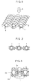
- Fig. 1 is a perspective view of a prior art heat exchanger for an air conditioner, disclosed in Japanese Patent Laid-open (Kokai) No. 61-153388 and Fig. 2 is a sectional view of the heat exchanger of Fig. 1.
- the heat exchanger is formed by alternately passing fine wires 2a and 2b, which serve as fins, over and under heat-transfer tubes 1 through which a heat exchanging fluid, such as a cooling medium, flows in the direction of the arrow B so that the fine wire fins 2a and 2b are in close contact with the heat-transfer tubes 1.
- the heat-transfer tubes 1 are very thin tubes having, for example, an outside diameter in the range of 1 to 2 mm and an inside diameter in the range of 0.7 to 1.7 mm.
- a current of an external fluid for example, air
- flowing in the direction of the arrow A (Fig. 1) toward the plurality of parallel heat-transfer tubes 1 threads its way through spaces between the fine wire fins 2a and 2b, exchanging heat with the heat-transfer tubes 1 and the fine wire fins 2a and 2b.
- the current of the external fluids is disturbed by the fine wires 2, the current of the external fluid falling on the fine wire fins is deflected to right and left as shown by arrows in Fig. 3, and part of the external fluid flows along the fine wire fins and rises along the surfaces of the heat-transfer tubes 1, so that the external fluid is able to be in contact with the heat-transfer tubes 1 for a comparatively long contact time.
- the contact area in which the fine wire fins 2a and 2b are in contact with the heat-transfer tubes 1 is very small. Therefore, the fine wire fins 2a and 2b do not reduce the contact area in which the external fluid comes into contact with the heat-transfer tubes 1 and hence heat can effectively be transferred between the external fluid and the heat-transfer tubes 1.
- the heat-transfer rate of this prior art heat exchanger is greater than that of a conventional heat exchanger for air conditioner, the heat-transfer area of the prior art heat exchanger is 1/5 or below that of a conventional heat exchanger having the same front area because the prior art heat exchanger has a very small thickness in the range of 1 to 3 mm.
- a heat exchanger formed by stacking a plurality of heat exchanging units of the type similar to this prior art heat exchanger may be used to secure a necessary heat exchanging quantity.
- the heat exchanger having the plurality of heat exchanging units increases the pressure loss of air, the flow of air is reduced and, consequently, it is impossible to secure a necessary heat exchanging quantity unless the power of the blower is increased.
- Further object of the present invention is to provide a heat exchanger for an air conditioner, having an increased heat-transfer area capable of exchanging heat at an increased heat exchanging quantity, and requiring a reduced space for installation.
- a heat exchanger for an air conditioner comprises a plurality of parallel heat-transfer tubes arranged at predetermined intervals, fine wires serving as heat-transfer fins and passed alternately over and under the heat-transfer tubes so as to form a heat-transfer surface of a plain weave together with the heat-transfer tubes, and fine wire pillars inserted in the heat-transfer surface defined by the heat-transfer tubes and the fine wires.
- the intervals between the fine wires passed alternately over and under the heat-transfer tubes are at least twice the diameter of the fine wires.
- the fine wire pillars are joined fixedly at least to either the fine wires or the heat-transfer tubes.
- the heat exchanger thus constructed has an increased heat-transfer area in flowing direction of air.
- the fine wire fins are arranged at comparatively large intervals, condensed water droplets are hardly able to stay on the heat exchanger, the heat exchanger is hardly clogged with condensed water droplets even if the surface of the heat exchanger is wet during operation, and reduction in the heat exchanging quantity due to reduction in the flow of air can be surpressed.
- the second fine wires are bent in the shape of the inverted letter V so that the opposite sides of each second fine wire extend obliquely downward.
- This construction promotes condensed water droplets falling by gravity when the heat exchanger ist used in a moist atmosphere where moisture contained in the atmosphere condenses.
- the heat exchanger is hardly clogged with water droplets even if the surface of the heat exchanger ist wet during operation, and reduction in the heat exchanging quantity due to reduction in the flow of the external fluid can be surpressed.
- a heat exchanger for an air conditioner in a preferred mode of the present invention comprises a plurality of heat-transfer tubes through which a nonazeotropic cooling medium flows, a plurality of fine wires, and a plurality of heat-transfer members arranged perpendicularly to the flowing direction of an external fluid in a plurality of banks and parallel to each other, and connected to each other.
- the cooling medium is supplied so as to flow from the heat-transfer member disposed at the lowermost position with respect to the flow of the external fluid through the heat-transfer tubes toward the heat-transfer member disposed at the uppermost position.
- the heat exchanging performance of this heat exchanger ist higher than that of a heat exchanger of a simple crossflow type (a heat exchanger with a single crossflow heat exchanging unit).
- heat-transfer tubes 1 are arranged at predetermined intervals to pass an internal fluid, such as a cooling medium, and fine wires are passed alternately over and under the heat-transfer tubes 1 to form fine wire fins 2a and 2b, i.e., heat-transfer fins. Intervals between the fine wire fins 2a and 2b as the weft are twice the diameter of the fine wire or above.
- Needle fins 6 are inserted perpendicularly to a heat-transfer surface formed by interlacing the fine wires and the heat-transfer tubes 1 in spaces defined by the fine wire fins and the heat-transfer tubes 1, and the needle fins 6 are attached to the fine wire fins 2a and 2b, or the heat-transfer tubes 1.
- an external fluid such as air threads its way through spaces between the fine wire fins 2a and 2b, needle fins 6 and the heat-transfer tubes 1, generating minute vortices.
- the minute vortices swirl in turbulent currents around portions on the lower side with respect to the flowing direction of the air of the fine wire fins 2a and 2b, the needle fins 6 and the heat-transfer tubes 1.
- the needle fins 6 increases the heat-transfer area along the flowing direction of the air, the heat exchanging quantity can be increased. Since the intervals between the fine wire fins 2a and 2b are increased and spaces between the fine wire fins 2a and 2b are expanded by the needle fins 6, condensed water droplets are hardly able to stay on the heat exchanger when the heat exchanger is used in a moist atmosphere where moisture contained in the atmosphere condenses in water droplets on the heat exchanger, the heat exchanger is hardly clogged with condensed water droplets, and reduction in heat exchanging quantity due to reduction in the flow of the air can be suppressed.
- heat-transfer tubes 1 are arranged at perdetermined intervals to pass an internal fluid, such as a cooling medium, and fine wires are passed alternately over and under the heat-transfer tubes 1 to form fine wire fins 2a and 2b, i.e., heat-transfer fins. Intervals between the fine wire fins 2a, 2b as the weft are twice the diameter of the fine wire or above.
- Needle fins 6 are inserted in spaces formed between the heat-transfer tubes 1 and the fine wire fins so as to extend obliquely downward, and the needle fins 6 are attached to the fine wire fins 2a and 2b, or the heat-transfer tubes 1.
- the needle fins 6 are bent in a plane perendicular to the axes of the heat-transfer tubes 1 in this embodiment, the needle fins 6 may be bent in a plane parallel to the axes of the heat-transfer tubes 1 provided that the top of the needle fins 6 looks obliquely downward.
- FIG. 6 showing a heat exchanger for an air conditioner
- a third embodiment according to the present invention in a fragmentary sectional view
- heat-transfer tubes 1 fine wires are passed alternately over and under the heat-transfer tubes 1 of each row to form fine wire fins 2, and headers 3.
- the heat exchanger in this embodiment has a plurality of heat-transfer surfaces.
- a nonazeotropic cooling medium is used as an internal operating fluid in the heat-transfer tubes 1.
- the nonazeotropic cooling medium flows from the rear header 3 into the heat-transfer tubes 1 of the rear row in the direction of the arrow B, flows sequentially through the headers 3 and the heat-transfer tubes 1 of the intermediate rows toward the heat-transfer tubes 1 of the front row, and flows into the front header 3.
- the nonazeotropic cooling medium flows across the flow of air flowing in the direction of the arrow A in a virtually counterflow mode.
- the nonazeotropic cooling medium is used as an internal operating fluid that flows through the heat-transfer tubes 1, the temperature of the nonazeotropic cooling medium, which phase change occurs in the heat exchanger, changes.
- the heat exchanging quantity of a heat exchanger provided with heat-transfer tubes arranged in a plurality of rows in which the nonazeotropic cooling medium flows across the air flow in a virtually counterflow mode, is higher than that of a heat exchanger provided with heat-transfer tubes arranged in a single row, in which the nonazeotropic cooling medium flows simply across the air flow, which will be obvious from Fig. 8. Therefore, by the construction of the heat exchanger as shown in Fig. 6, the heat exchanging quantity of the heat exchanger becomes higher. It is also possible to bent heat-transfer surfaces without intermediate headers 3 as shown in Fig. 7.
Applications Claiming Priority (7)
| Application Number | Priority Date | Filing Date | Title |
|---|---|---|---|
| JP17130794 | 1994-07-22 | ||
| JP17130794 | 1994-07-22 | ||
| JP171307/94 | 1994-07-22 | ||
| JP25835194 | 1994-10-24 | ||
| JP258351/94 | 1994-10-24 | ||
| JP25835194 | 1994-10-24 | ||
| EP95104993A EP0693666B1 (de) | 1994-07-22 | 1995-04-04 | Wärmetauscher für eine Klimaanlage |
Related Parent Applications (1)
| Application Number | Title | Priority Date | Filing Date |
|---|---|---|---|
| EP95104993A Division EP0693666B1 (de) | 1994-07-22 | 1995-04-04 | Wärmetauscher für eine Klimaanlage |
Publications (3)
| Publication Number | Publication Date |
|---|---|
| EP0862037A2 true EP0862037A2 (de) | 1998-09-02 |
| EP0862037A3 EP0862037A3 (de) | 1998-09-16 |
| EP0862037B1 EP0862037B1 (de) | 2001-10-31 |
Family
ID=26494074
Family Applications (4)
| Application Number | Title | Priority Date | Filing Date |
|---|---|---|---|
| EP98108087A Expired - Lifetime EP0864835B1 (de) | 1994-07-22 | 1995-04-04 | Wärmetauscher |
| EP98108085A Expired - Lifetime EP0860674B1 (de) | 1994-07-22 | 1995-04-04 | Wärmetauscher |
| EP98108086A Expired - Lifetime EP0862037B1 (de) | 1994-07-22 | 1995-04-04 | Wärmetauscher |
| EP95104993A Expired - Lifetime EP0693666B1 (de) | 1994-07-22 | 1995-04-04 | Wärmetauscher für eine Klimaanlage |
Family Applications Before (2)
| Application Number | Title | Priority Date | Filing Date |
|---|---|---|---|
| EP98108087A Expired - Lifetime EP0864835B1 (de) | 1994-07-22 | 1995-04-04 | Wärmetauscher |
| EP98108085A Expired - Lifetime EP0860674B1 (de) | 1994-07-22 | 1995-04-04 | Wärmetauscher |
Family Applications After (1)
| Application Number | Title | Priority Date | Filing Date |
|---|---|---|---|
| EP95104993A Expired - Lifetime EP0693666B1 (de) | 1994-07-22 | 1995-04-04 | Wärmetauscher für eine Klimaanlage |
Country Status (9)
| Country | Link |
|---|---|
| US (3) | US5769157A (de) |
| EP (4) | EP0864835B1 (de) |
| KR (1) | KR100222015B1 (de) |
| CN (1) | CN1062952C (de) |
| AU (2) | AU694706B2 (de) |
| DE (4) | DE69517710T2 (de) |
| ES (4) | ES2149030T3 (de) |
| HK (1) | HK1006657A1 (de) |
| MY (2) | MY134032A (de) |
Cited By (1)
| Publication number | Priority date | Publication date | Assignee | Title |
|---|---|---|---|---|
| GB2452369A (en) * | 2007-08-31 | 2009-03-04 | Retermia Oy | Equipment and method for making a needle fin tube, and a needle fin tube |
Families Citing this family (23)
| Publication number | Priority date | Publication date | Assignee | Title |
|---|---|---|---|---|
| US5806585A (en) * | 1995-02-27 | 1998-09-15 | Mitsubishi Denki Kabushiki Kaisha | Heat exchanger, refrigeration system, air conditioner, and method and apparatus for fabricating heat exchanger |
| JPH08270973A (ja) * | 1995-03-30 | 1996-10-18 | Mitsubishi Electric Corp | 空気調和機 |
| JPH09296994A (ja) * | 1996-04-30 | 1997-11-18 | Sanden Corp | 熱交換器 |
| WO2002005925A1 (de) * | 2000-07-17 | 2002-01-24 | August Schmid-Stiftung Zürich | Filter-einrichtung, insbesondere für eine flüssigkeit |
| DE10141490A1 (de) * | 2001-08-24 | 2003-03-13 | Behr Gmbh & Co | Kühler und Verfahren zum Kühlen eines Mediums |
| US6892803B2 (en) * | 2002-11-19 | 2005-05-17 | Modine Manufacturing Company | High pressure heat exchanger |
| US6959758B2 (en) * | 2002-12-03 | 2005-11-01 | Modine Manufacturing Company | Serpentine tube, cross flow heat exchanger construction |
| US7140426B2 (en) | 2003-08-29 | 2006-11-28 | Plascore, Inc. | Radiant panel |
| EP1707912A1 (de) * | 2005-04-01 | 2006-10-04 | Fiwihex B.V. | Wärmetauscher und Gewächshaus |
| NL1029280C1 (nl) * | 2005-06-17 | 2006-12-19 | Fiwihex B V | Behuizing met een koeling. |
| JP4852981B2 (ja) * | 2005-11-02 | 2012-01-11 | 株式会社ノーリツ | 温水装置 |
| KR100739196B1 (ko) * | 2006-01-04 | 2007-07-13 | 엘지전자 주식회사 | 핀-튜브 열교환기 |
| DE102006022629A1 (de) * | 2006-05-12 | 2007-11-15 | Spörl KG | Wärmetauschvorrichtung für einen Wärmeaustausch zwischen Medien und Webstruktur |
| US20090242184A1 (en) * | 2007-01-31 | 2009-10-01 | Shi Mechanical & Equipment Inc. | Spiral Tube Fin Heat Exchanger |
| US20100122806A1 (en) * | 2008-11-14 | 2010-05-20 | Nordyne Inc. | Compact and Efficient Heat Exchanger, Furnace, HVAC Unit, Building, and Method of Making |
| PL221028B1 (pl) | 2011-06-24 | 2016-02-29 | Aic Spółka Akcyjna | Pakiet rurowy wymiennika ciepła |
| ES2611304T3 (es) * | 2011-12-21 | 2017-05-08 | Sandvik Intellectual Property Ab | Una caldera de vapor que comprende un elemento de radiación |
| WO2016144276A1 (en) * | 2015-03-11 | 2016-09-15 | Atm Beyaz Eşya Parçalari Sanayi̇ Ve Ti̇caret Li̇mi̇ted Şi̇rketi̇ | Staggered heat exchanger connected in series and method for manufacturing the same |
| US10982913B2 (en) * | 2015-05-22 | 2021-04-20 | The Johns Hopkins University | Three dimensional woven lattices as multi-functional heat exchanger |
| US11480398B2 (en) * | 2015-05-22 | 2022-10-25 | The Johns Hopkins University | Combining complex flow manifold with three dimensional woven lattices as a thermal management unit |
| US10422586B2 (en) | 2015-11-10 | 2019-09-24 | Hamilton Sundstrand Corporation | Heat exchanger |
| DE102016224338A1 (de) * | 2016-12-07 | 2018-06-07 | Fraunhofer-Gesellschaft zur Förderung der angewandten Forschung e.V. | Wärmeübertrager und Verfahren zu dessen Verwendung |
| CN112771342B (zh) * | 2018-10-05 | 2022-12-16 | 三菱电机株式会社 | 热交换器及制冷循环装置 |
Citations (7)
| Publication number | Priority date | Publication date | Assignee | Title |
|---|---|---|---|---|
| FR748179A (fr) * | 1932-07-28 | 1933-06-29 | Perfectionnements à la construction de tubes de transmission de chaleur | |
| DE654158C (de) * | 1934-10-24 | 1937-12-14 | Henry Dieterlen | Waermeaustauscher |
| GB636615A (en) * | 1947-07-03 | 1950-05-03 | Gen Electric Co Ltd | Improvements in and relating to heat-exchangers for exchanging heat between a solid surface and a fluid |
| FR1017029A (fr) * | 1949-06-25 | 1952-11-28 | Air Preheater | Procédé pour la fixation d'ailettes en forme de broches à des éléments tubulaires d'échangeurs de chaleur |
| DE975537C (de) * | 1948-04-28 | 1962-01-11 | Svenska Maskinverken Ab | Waermeaustauscher |
| FR2428224A2 (fr) * | 1978-06-06 | 1980-01-04 | Martel Catala & Cie Ets | Perfectionnements aux faisceaux tubulaires et a leur procede de fabrication |
| JPS61153388A (ja) * | 1984-12-26 | 1986-07-12 | Kawasaki Steel Corp | 熱交換装置 |
Family Cites Families (19)
| Publication number | Priority date | Publication date | Assignee | Title |
|---|---|---|---|---|
| FR793344A (fr) * | 1934-10-24 | 1936-01-22 | échangeur thermique | |
| DE851203C (de) * | 1939-06-04 | 1952-10-02 | Siemens Ag | Rohrfoermiger Waermeaustauscher, insbesondere Kondensator fuer Kaeltemaschinen |
| US2588500A (en) * | 1945-08-18 | 1952-03-11 | Hugh C Dugan | Process for making heat exchangers |
| US2500501A (en) * | 1946-09-12 | 1950-03-14 | Kellogg M W Co | Method of making heat exchangers |
| US2469635A (en) * | 1948-01-03 | 1949-05-10 | Svenska Maskinverken Ab | Steam boiler or the like having extended heat transfer surfaces |
| US2620170A (en) * | 1950-08-18 | 1952-12-02 | United States Steel Corp | Heat transfer unit |
| US2952906A (en) * | 1956-08-17 | 1960-09-20 | Reynolds Metals Co | Method of soldering aluminum to copper or brass |
| DE1132883B (de) * | 1957-01-30 | 1962-07-12 | Franciscus Roffelsen | Verfahren zum Herstellung von Waermeaustauschelementen |
| GB976003A (en) * | 1962-07-13 | 1964-11-25 | Reiert Aluminium Metall | A heat exchanger |
| FR2045742B1 (de) * | 1969-06-30 | 1974-02-22 | Chausson Usines Sa | |
| US4056143A (en) * | 1972-11-08 | 1977-11-01 | The Plessey Company Limited | Heat exchange apparatus |
| JPS5730583A (en) * | 1980-07-29 | 1982-02-18 | Muneyuki Sakamoto | Selecting method in line transportation |
| DE3309923C2 (de) * | 1983-03-19 | 1985-10-31 | Rolf Dipl.-Ing. 4100 Duisburg Bähr | Wärmetauscher |
| JPS61153389A (ja) * | 1984-12-26 | 1986-07-12 | Kawasaki Steel Corp | 熱交換装置の流体変向装置 |
| JPS61181970A (ja) * | 1985-02-07 | 1986-08-14 | Hitachi Cable Ltd | 光フアイバを用いた分散位置におけるセンシング方式 |
| JPS6415087A (en) * | 1987-07-08 | 1989-01-19 | Nippi Kikai Kk | Taking-in apparatus for leather and the like |
| JPH0236781A (ja) * | 1988-07-22 | 1990-02-06 | Mitsubishi Electric Corp | 電気機器の押釦制御装置 |
| JPH05133691A (ja) * | 1991-11-08 | 1993-05-28 | Daikin Ind Ltd | 熱交換器およびその製造方法 |
| JPH0650689A (ja) * | 1992-07-30 | 1994-02-25 | Sharp Corp | 熱交換器およびその製造方法ならびに金属製管路と金属製線材との接続方法 |
-
1995
- 1995-04-04 EP EP98108087A patent/EP0864835B1/de not_active Expired - Lifetime
- 1995-04-04 ES ES98108085T patent/ES2149030T3/es not_active Expired - Lifetime
- 1995-04-04 EP EP98108085A patent/EP0860674B1/de not_active Expired - Lifetime
- 1995-04-04 EP EP98108086A patent/EP0862037B1/de not_active Expired - Lifetime
- 1995-04-04 ES ES95104993T patent/ES2135614T3/es not_active Expired - Lifetime
- 1995-04-04 DE DE69517710T patent/DE69517710T2/de not_active Expired - Lifetime
- 1995-04-04 ES ES98108087T patent/ES2152111T3/es not_active Expired - Lifetime
- 1995-04-04 DE DE69523639T patent/DE69523639T2/de not_active Expired - Lifetime
- 1995-04-04 DE DE69519445T patent/DE69519445T2/de not_active Expired - Lifetime
- 1995-04-04 ES ES98108086T patent/ES2165111T3/es not_active Expired - Lifetime
- 1995-04-04 US US08/417,159 patent/US5769157A/en not_active Expired - Lifetime
- 1995-04-04 EP EP95104993A patent/EP0693666B1/de not_active Expired - Lifetime
- 1995-04-04 DE DE69510504T patent/DE69510504T2/de not_active Expired - Lifetime
- 1995-04-25 CN CN95104783A patent/CN1062952C/zh not_active Expired - Fee Related
- 1995-07-11 KR KR1019950020258A patent/KR100222015B1/ko not_active IP Right Cessation
- 1995-07-17 MY MYPI20022866A patent/MY134032A/en unknown
- 1995-07-17 MY MYPI95002015A patent/MY115441A/en unknown
-
1996
- 1996-06-06 US US08/659,763 patent/US5822854A/en not_active Expired - Lifetime
-
1997
- 1997-10-24 AU AU42827/97A patent/AU694706B2/en not_active Ceased
- 1997-10-24 AU AU42828/97A patent/AU694707B2/en not_active Ceased
-
1998
- 1998-02-10 US US09/021,343 patent/US5964284A/en not_active Expired - Lifetime
- 1998-06-23 HK HK98106053A patent/HK1006657A1/xx not_active IP Right Cessation
Patent Citations (7)
| Publication number | Priority date | Publication date | Assignee | Title |
|---|---|---|---|---|
| FR748179A (fr) * | 1932-07-28 | 1933-06-29 | Perfectionnements à la construction de tubes de transmission de chaleur | |
| DE654158C (de) * | 1934-10-24 | 1937-12-14 | Henry Dieterlen | Waermeaustauscher |
| GB636615A (en) * | 1947-07-03 | 1950-05-03 | Gen Electric Co Ltd | Improvements in and relating to heat-exchangers for exchanging heat between a solid surface and a fluid |
| DE975537C (de) * | 1948-04-28 | 1962-01-11 | Svenska Maskinverken Ab | Waermeaustauscher |
| FR1017029A (fr) * | 1949-06-25 | 1952-11-28 | Air Preheater | Procédé pour la fixation d'ailettes en forme de broches à des éléments tubulaires d'échangeurs de chaleur |
| FR2428224A2 (fr) * | 1978-06-06 | 1980-01-04 | Martel Catala & Cie Ets | Perfectionnements aux faisceaux tubulaires et a leur procede de fabrication |
| JPS61153388A (ja) * | 1984-12-26 | 1986-07-12 | Kawasaki Steel Corp | 熱交換装置 |
Non-Patent Citations (1)
| Title |
|---|
| PATENT ABSTRACTS OF JAPAN vol. 010, no. 357 (M-540), 2 December 1986 & JP 61 153388 A (KAWASAKI STEEL CORP), 12 July 1986, * |
Cited By (2)
| Publication number | Priority date | Publication date | Assignee | Title |
|---|---|---|---|---|
| GB2452369A (en) * | 2007-08-31 | 2009-03-04 | Retermia Oy | Equipment and method for making a needle fin tube, and a needle fin tube |
| GB2452369B (en) * | 2007-08-31 | 2012-07-11 | Retermia Oy | Equipment and method for making a needle-fin tube |
Also Published As
Similar Documents
| Publication | Publication Date | Title |
|---|---|---|
| EP0862037B1 (de) | Wärmetauscher | |
| US5186022A (en) | Evaporator structure for refrigerator-freezer | |
| US20070199686A1 (en) | Heat exchanger | |
| US20090173480A1 (en) | Louvered air center with vortex generating extensions for compact heat exchanger | |
| US20100107675A1 (en) | Heat exchanger with improved condensate removal | |
| JPH04227479A (ja) | 改良式波形伝熱表面 | |
| JP3264525B2 (ja) | 熱交換器 | |
| US7065982B2 (en) | Evaporator for refrigeration systems | |
| JPH08178366A (ja) | 熱交換器 | |
| US20030150601A1 (en) | Heat exchanger fin for air conditioner | |
| EP3224565B1 (de) | Frosttoleranter mikrokanalwärmetauscher | |
| JP3851403B2 (ja) | 空気調和機用室内ユニット | |
| US5353866A (en) | Heat transfer fins and heat exchanger | |
| KR940004982B1 (ko) | 물결판형핀의 흡입향상 장치 | |
| KR100237866B1 (ko) | 멀티패스증발기 | |
| JPH0755380A (ja) | 熱交換器 | |
| JP3215587B2 (ja) | 熱交換器 | |
| US8196646B2 (en) | Heat exchanger assembly | |
| JPH11230638A (ja) | 熱交換器 | |
| JP3886244B2 (ja) | 熱交換器 | |
| JP2810361B2 (ja) | フィン・チューブ熱交換器 | |
| JPS5822059Y2 (ja) | 蒸発器 | |
| KR100314186B1 (ko) | 증발기용 트라이 튜브 열교환기 | |
| JPH0666458A (ja) | 冷媒蒸発器 | |
| JP2719004B2 (ja) | 熱交換器 |
Legal Events
| Date | Code | Title | Description |
|---|---|---|---|
| PUAI | Public reference made under article 153(3) epc to a published international application that has entered the european phase |
Free format text: ORIGINAL CODE: 0009012 |
|
| PUAL | Search report despatched |
Free format text: ORIGINAL CODE: 0009013 |
|
| 17P | Request for examination filed |
Effective date: 19980504 |
|
| AC | Divisional application: reference to earlier application |
Ref document number: 693666 Country of ref document: EP |
|
| AK | Designated contracting states |
Kind code of ref document: A2 Designated state(s): BE DE ES FR GB IT |
|
| AK | Designated contracting states |
Kind code of ref document: A3 Designated state(s): BE DE ES FR GB IT |
|
| 17Q | First examination report despatched |
Effective date: 19990127 |
|
| GRAG | Despatch of communication of intention to grant |
Free format text: ORIGINAL CODE: EPIDOS AGRA |
|
| GRAG | Despatch of communication of intention to grant |
Free format text: ORIGINAL CODE: EPIDOS AGRA |
|
| GRAH | Despatch of communication of intention to grant a patent |
Free format text: ORIGINAL CODE: EPIDOS IGRA |
|
| GRAH | Despatch of communication of intention to grant a patent |
Free format text: ORIGINAL CODE: EPIDOS IGRA |
|
| GRAA | (expected) grant |
Free format text: ORIGINAL CODE: 0009210 |
|
| AC | Divisional application: reference to earlier application |
Ref document number: 693666 Country of ref document: EP |
|
| AK | Designated contracting states |
Kind code of ref document: B1 Designated state(s): BE DE ES FR GB IT |
|
| REF | Corresponds to: |
Ref document number: 69523639 Country of ref document: DE Date of ref document: 20011206 |
|
| REG | Reference to a national code |
Ref country code: GB Ref legal event code: IF02 |
|
| ET | Fr: translation filed | ||
| REG | Reference to a national code |
Ref country code: ES Ref legal event code: FG2A Ref document number: 2165111 Country of ref document: ES Kind code of ref document: T3 |
|
| PLBE | No opposition filed within time limit |
Free format text: ORIGINAL CODE: 0009261 |
|
| STAA | Information on the status of an ep patent application or granted ep patent |
Free format text: STATUS: NO OPPOSITION FILED WITHIN TIME LIMIT |
|
| 26N | No opposition filed | ||
| REG | Reference to a national code |
Ref country code: GB Ref legal event code: 746 Effective date: 20051025 |
|
| PGFP | Annual fee paid to national office [announced via postgrant information from national office to epo] |
Ref country code: ES Payment date: 20120424 Year of fee payment: 18 |
|
| PGFP | Annual fee paid to national office [announced via postgrant information from national office to epo] |
Ref country code: DE Payment date: 20130327 Year of fee payment: 19 Ref country code: GB Payment date: 20130403 Year of fee payment: 19 Ref country code: BE Payment date: 20130415 Year of fee payment: 19 |
|
| PGFP | Annual fee paid to national office [announced via postgrant information from national office to epo] |
Ref country code: FR Payment date: 20130625 Year of fee payment: 19 |
|
| PGFP | Annual fee paid to national office [announced via postgrant information from national office to epo] |
Ref country code: IT Payment date: 20130423 Year of fee payment: 19 |
|
| REG | Reference to a national code |
Ref country code: DE Ref legal event code: R119 Ref document number: 69523639 Country of ref document: DE |
|
| GBPC | Gb: european patent ceased through non-payment of renewal fee |
Effective date: 20140404 |
|
| REG | Reference to a national code |
Ref country code: FR Ref legal event code: ST Effective date: 20141231 |
|
| REG | Reference to a national code |
Ref country code: DE Ref legal event code: R119 Ref document number: 69523639 Country of ref document: DE Effective date: 20141101 |
|
| PG25 | Lapsed in a contracting state [announced via postgrant information from national office to epo] |
Ref country code: GB Free format text: LAPSE BECAUSE OF NON-PAYMENT OF DUE FEES Effective date: 20140404 Ref country code: DE Free format text: LAPSE BECAUSE OF NON-PAYMENT OF DUE FEES Effective date: 20141101 |
|
| PG25 | Lapsed in a contracting state [announced via postgrant information from national office to epo] |
Ref country code: FR Free format text: LAPSE BECAUSE OF NON-PAYMENT OF DUE FEES Effective date: 20140430 |
|
| PG25 | Lapsed in a contracting state [announced via postgrant information from national office to epo] |
Ref country code: IT Free format text: LAPSE BECAUSE OF NON-PAYMENT OF DUE FEES Effective date: 20140404 |
|
| REG | Reference to a national code |
Ref country code: ES Ref legal event code: FD2A Effective date: 20150527 |
|
| PG25 | Lapsed in a contracting state [announced via postgrant information from national office to epo] |
Ref country code: ES Free format text: LAPSE BECAUSE OF NON-PAYMENT OF DUE FEES Effective date: 20140405 |
|
| PG25 | Lapsed in a contracting state [announced via postgrant information from national office to epo] |
Ref country code: BE Free format text: LAPSE BECAUSE OF NON-PAYMENT OF DUE FEES Effective date: 20140430 |