EP0862015B1 - Projecteur pour véhicules - Google Patents
Projecteur pour véhicules Download PDFInfo
- Publication number
- EP0862015B1 EP0862015B1 EP98103263A EP98103263A EP0862015B1 EP 0862015 B1 EP0862015 B1 EP 0862015B1 EP 98103263 A EP98103263 A EP 98103263A EP 98103263 A EP98103263 A EP 98103263A EP 0862015 B1 EP0862015 B1 EP 0862015B1
- Authority
- EP
- European Patent Office
- Prior art keywords
- reflector
- light
- support element
- light stopping
- stopping member
- Prior art date
- Legal status (The legal status is an assumption and is not a legal conclusion. Google has not performed a legal analysis and makes no representation as to the accuracy of the status listed.)
- Expired - Lifetime
Links
Images


Classifications
-
- B—PERFORMING OPERATIONS; TRANSPORTING
- B60—VEHICLES IN GENERAL
- B60Q—ARRANGEMENT OF SIGNALLING OR LIGHTING DEVICES, THE MOUNTING OR SUPPORTING THEREOF OR CIRCUITS THEREFOR, FOR VEHICLES IN GENERAL
- B60Q1/00—Arrangement of optical signalling or lighting devices, the mounting or supporting thereof or circuits therefor
- B60Q1/02—Arrangement of optical signalling or lighting devices, the mounting or supporting thereof or circuits therefor the devices being primarily intended to illuminate the way ahead or to illuminate other areas of way or environments
- B60Q1/04—Arrangement of optical signalling or lighting devices, the mounting or supporting thereof or circuits therefor the devices being primarily intended to illuminate the way ahead or to illuminate other areas of way or environments the devices being headlights
- B60Q1/14—Arrangement of optical signalling or lighting devices, the mounting or supporting thereof or circuits therefor the devices being primarily intended to illuminate the way ahead or to illuminate other areas of way or environments the devices being headlights having dimming means
- B60Q1/1415—Dimming circuits
-
- F—MECHANICAL ENGINEERING; LIGHTING; HEATING; WEAPONS; BLASTING
- F21—LIGHTING
- F21S—NON-PORTABLE LIGHTING DEVICES; SYSTEMS THEREOF; VEHICLE LIGHTING DEVICES SPECIALLY ADAPTED FOR VEHICLE EXTERIORS
- F21S41/00—Illuminating devices specially adapted for vehicle exteriors, e.g. headlamps
- F21S41/40—Illuminating devices specially adapted for vehicle exteriors, e.g. headlamps characterised by screens, non-reflecting members, light-shielding members or fixed shades
- F21S41/47—Attachment thereof
-
- F—MECHANICAL ENGINEERING; LIGHTING; HEATING; WEAPONS; BLASTING
- F21—LIGHTING
- F21S—NON-PORTABLE LIGHTING DEVICES; SYSTEMS THEREOF; VEHICLE LIGHTING DEVICES SPECIALLY ADAPTED FOR VEHICLE EXTERIORS
- F21S41/00—Illuminating devices specially adapted for vehicle exteriors, e.g. headlamps
- F21S41/60—Illuminating devices specially adapted for vehicle exteriors, e.g. headlamps characterised by a variable light distribution
- F21S41/68—Illuminating devices specially adapted for vehicle exteriors, e.g. headlamps characterised by a variable light distribution by acting on screens
- F21S41/683—Illuminating devices specially adapted for vehicle exteriors, e.g. headlamps characterised by a variable light distribution by acting on screens by moving screens
- F21S41/686—Blades, i.e. screens moving in a vertical plane
Definitions
- the invention relates to a headlight for vehicles with a two Cup-shaped reflector with firing locations, with a in a firing location of the Reflector arranged light source, with a between a lens and the Reflector arranged adjustable screen, which is attached to a fixed plate-shaped carrier element is attached and by a remotely operable Adjusting device at least in a high beam and low beam position is adjustable.
- the Adjustment device is outside of an consisting of reflector, aperture and lens arranged optical system, and the location for the fixed plate-shaped carrier element and for the setting device does not go from EP 0 723 108 A1.
- the aperture is in its high and low beam position by a vertical guidance of the support plate adjustable or around a horizontal and transverse to optical axis pivoting axis. In the vertical guide can the screen is slightly tilted. When swiveling the aperture around the horizontal Axes of light can be shielded, which are used to illuminate the Serve close range in front of the vehicle, and thus can temporarily undesirable dark zone in the vicinity in front of the vehicle.
- the aperture is switched to the right and left-hand position by Swiveling the aperture in the direction of light emission and in the vertical Central axis of the reflector.
- An asymmetrical low beam to obtain, the aperture has two at different levels Aperture edge sections.
- the adjustable aperture is in its high beam position arranged below the upper edge of the plate-shaped carrier element.
- the upper edge of the support element serves as a diaphragm edge to create a Light / dark limit for high beam.
- a headlight for vehicles has become known from DE 38 06 658 A1, at that as a support element of the panel on the front edge of the reflector attached support frame of the lens is used.
- the aperture is around a horizontal and axis running perpendicular to the optical axis in its high and low beam position pivotable.
- the adjustment device for the aperture is on the rear of the reflector arranged and formed by an electric solenoid.
- the solenoid is with a long lifting rod, which runs below the reflector downward swivel arm of the panel articulated.
- the assembly the adjustment device is time consuming and cumbersome since it is on the back the reflector is to be attached and the free end of its lifting rod with the Swivel arm of the panel is to be connected and thus the setting device and the Cover are not a pre-assembled unit. It also builds out of reflector, aperture and lens formed system larger in size since the Adjustment device and its long lifting rod arranged outside the system is.
- a headlight for vehicles which has become known from DE 41 02 586 A1 has an adjustable aperture, which the light / dark boundary of an asymmetrical Low beam is generated and continuously adjustable, so the light / dark line the low beam of the inclination of the vehicle, especially one Motorcycle, can customize. Switching the aperture for high and low beam can not.
- the adjustable cover is designed so that it shields all interfering light rays from the light source below its aperture edge.
- An arm-shaped support element for the adjustable panel and the electrical Adjustment device is attached to the reflector.
- the panel On the one pointing upwards End section of the support element, the panel is pivotable about an axis stored, which coincides with the optical axis of the headlamp.
- the lower end portion of the support element protrudes from the reflector, aperture and Lens formed system out and carries the electrical at this end section Adjustment.
- Headlights are known from US Pat. No. 5,161,875 and FR 2 114 887, in which a remote-controlled setting device at least partially within one of a reflector, at least one adjustable diaphragm and a lens arranged optical system and below the adjustable panel on one fixed support element is attached.
- the adjustable aperture is not in one High and low beam position adjustable.
- a headlight known from EP 0 429 922 B1 has one by hand adjustable aperture, through which only dimmed light figures can be generated.
- the adjustable aperture is one in the direction of light emission extending axis pivotable and at a distance from the vertical central plane of the Headlights below the one running at a lower level Diaphragm edge section of the diaphragm arranged.
- the object of the invention is that described in the preamble of claim 1
- This object is achieved by the invention
- the deepening can be so deep that the lockable cover, the lifting element and the Axis-forming bearings lie approximately in a surface that is adjacent to a main surface of the carrier element.
- By arranging the Adjustment device in the recess of the carrier element and through the near Arrangement of the lifting element to the main surface of the support element need not be that Carrier element create additional torques.
- the support element, the panel and the adjustment device together are an assembly unit, and the area of the Carrier element below the adjustable panel can be designed over a large area be that it shields all interfering light rays from the light source.
- the setting device is by the region of the carrier element of light beams arranged below the diaphragm shielded from the light source, which additionally heat the setting device would.
- a heat-insensitive setting device it is advantageous if it is set to the side of the support element facing the reflector at the area is attached below the panel.
- the setting device is by the Area of the support element below the panel to prevent insight into the Shielded headlight interior and does not have a special exterior Have appearance.
- the carrier element is very stable if it is at least up to Edge of the optical system formed by the reflector and lens extends and the entire front opening portion of the reflector, which is located below the adjustable panel. This allows below the adjustable aperture no more annoying light rays on the aperture pass.
- the reflector and the support element together form one torsionally rigid unit when the support element is below the adjustable Bezel and on either side of the adjustable bezel on the front edge of the Reflector is attached.
- the area of the carrier element arranged below the adjustable diaphragm can be designed very large, if the area upwards from a single-arm lever designed adjustable bezel which is limited in its Longitudinal extension adjacent to the upper edge area of the carrier element extends and is pivotable about an axis extending in the light exit direction. This allows an adjustment device, at least with most of it within the area of the support element.
- the adjustable aperture with your Aperture edge creates the light / dark boundary of an asymmetrical low beam and which by the remotely operated setting device in a low beam and one position giving the high beam is adjustable and two on has diaphragm edge sections running at different levels, from those in the position of the aperture for low beam or at a higher level running aperture edge section the section of the light / dark boundary for the Opposite lane side and the one running at a lower level Aperture edge section the section of the light / dark boundary for your own Generated roadway side, it is also advantageous if the aperture, which by one Light exit direction extending axis is pivotable at a distance from vertical middle plane below the one running at a lower level Aperture edge portion of the aperture is arranged.
- the aperture only can be adjusted by a very small swivel angle, by high beam and low beam to obtain. If the level is below that at a higher level Aperture edge section arranged axis of the aperture would be the Swivel angle of the screen is significantly larger and thus the adjustment time of the screen, larger and the area of the support element below the adjustable panel for the setting device smaller. In this context, it is also advantageous if the axis about which the screen can be swiveled through the upper one Edge area of the plate-shaped carrier element passes through.
- That Carrier element has a diaphragm edge for high beam, which in the position of High beam aperture runs above the adjustable aperture and with two Sections to the vertical center plane of the reflector is sloping. Because of the sloping sections of the upper edge region of the carrier element the axis about which the screen can be pivoted can be arranged higher, as if the diaphragm edge of the carrier element runs horizontally.
- the deepening of the Carrier element opened towards the lens and carries on its outside a below of the reflector arranged electronic device.
- the electronic device is at the through the recess is fastened and has a high rigidity due to its location outside the reflector, not that generated by the light source Exposed to heat.
- the electronic device controls the electrical supply of the Adjustment.
- the headlight for vehicles shown in Figure 1 has a cup-shaped Headlight housing (26), on the front edge of which a bowl-shaped, translucent cover plate (27) is placed.
- An optical system is adjustable, which consists of a headlight ellipsoidal reflector (1), a light source (2), an adjustable diaphragm (4) and a lens (3).
- the light source (2) is arranged.
- a light source (2) Serve filament of an incandescent lamp or an arc of a gas discharge lamp.
- the lamp is in a reflector opening (28) in the apex area of the reflector (1) used.
- the adjustable diaphragm (4) is close to one with its diaphragm edge (11) outer focal point of the ellipsoidal reflector (1) arranged.
- a The reflection surface of the ellipsoidal reflector (1) can be freely designed Be surface, that is, at least areas of the reflection surface are not through determines a mathematical function.
- the adjustable cover (4) and a remote-controlled setting device (6) are on a plate-shaped carrier element (5) attached.
- the plate-shaped Carrier element (5) is semicircular and below the horizontal Center plane of the reflector (1) on the front edge (29) of the reflector (1) appropriate. Therefore, the plate-shaped carrier element (5) runs in a surface through which the optical axis of the reflector (1) passes perpendicularly.
- the plate-shaped carrier element has on both sides of the vertical central plane of the Reflector (1) fastening means (30) through which the carrier element (5) the front edge (29) of the reflector (1) can be fastened.
- the aperture (4) is a one-armed lever, which on the carrier element (5) about an axis (10) in a Low beam and high beam position is pivotable.
- the cover (4) runs in its longitudinal extent adjacent to the upper edge region (9) of the Carrier element (5).
- In the low beam position of the aperture (4) runs its Aperture edge (11) above the carrier element (5) and produced with the diaphragm edge sections (12 and 13) running at different levels asymmetrical low beam.
- When swiveling the panel (4) from the Low beam position in the high beam position runs at least the majority of the Aperture edge (11) of the aperture (4) below an aperture edge (14) of the Carrier element (5).
- the diaphragm edge (14) of the carrier element (5) has two Sections (15), which towards the vertical center plane of the reflector (1) run sloping and thus result in a symmetrical high beam.
- the axis (10), around which the screen (4) is pivotable is near an outer edge section of the carrier element (5) and the reflector (1) and below that on a lower level Level diaphragm edge portion (13) of the diaphragm (4) arranged. This allows a smaller swivel angle (a) of the diaphragm (4) than if the Swivel axis below the one running at a higher level Diaphragm edge section (12) of the diaphragm (4) runs.
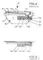
- the aperture (4) and the Adjustment device (6) are on the side of the reflector (1) facing away from the Carrier element (5) attached, the adjusting device (6) below the Elongated panel (4) attached to an area (7) of the carrier element (5) which is used to shield light rays from the light source (2).
- the Adjustment device (6) can, seen in the light exit direction, with its entire Expansion within the area (7) or if in Headlight housing sufficient space is available from the area (7) protrude.
- the adjusting device (6) has a first electromagnet (16) and a second or third electromagnet (18 or 23).
- a lifting magnet serves as the first electromagnet (16) Lifting element (20) when the first electromagnet (16) is activated counter to the force a holding device (17) the aperture (4) from the low beam in High beam position pivots.
- a helical one serves as the holding device (17) Compression spring, through which the from the housing of the first electromagnet (16) protruding end portion of the lifting element (20) and which between the free end portion of the lifting element (20) and the housing of the first electromagnet (16) is inserted under prestress.
- the stroke direction of the first electromagnet (16) runs approximately in the direction of the longitudinal extent the aperture (4) and the first electromagnet (16) is directly below that on the lower one Level extending diaphragm edge section (13) arranged.
- the lifting element (20) has a spherical head (31) at the free end, which fits into a faceplate (4) attached guide part (32) engages.
- the guide part (32) is one of the Cover (4) facing downwards.
- the ball head (31) of the lifting element (20) slides when pivoting the panel (4) in the approximately vertical Guide part (32).
- the second is when the headlights are on Electromagnet (18) is activated, and its force holds in addition to the force of the Holding device (17) the aperture (4) in the low beam position.
- a swing of the Aperture (4) from the high beam to the low beam position can also be through the common force of the holding device (17) and the second electromagnet (18) respectively.
- the second electromagnet (18) or a section of the carrier element (not shown) can act as a stop for the cover (4) in the low beam position serve.
- the first and second electromagnets (16 and 18) are over spacer elements (8) attached to the carrier element (5).
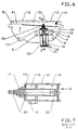
- FIGs 4 and 5 is the holding device (22), which the aperture (4) automatically by the high beam swivels into the low beam position and the cover (4) automatically in the low beam position, formed by a permanent magnet (22).
- the Permanent magnet (22) is in the housing (24) of a third electromagnet (23) integrated, which is a lifting magnet and articulated with the lifting element (25) Aperture (4) is connected.
- the aperture (4) is in the low beam position by the Force of the permanent magnet (22) held, which the lifting element (25) against one Stop in the housing of the third electromagnet (23) holds.
- the longitudinal axis of the Lifting element (25) runs approximately in the direction of the longitudinal extent of the diaphragm (4).
- the third electromagnet (23) When switching from low beam to high beam by activating the third electromagnet (23) the magnetic force of the permanent magnet (22) at least partially compensated, and the first electromagnet (16) swivels its attraction force the cover (4) up to one of the first electromagnet (16) formed stop (33).
- the third is in the high beam position of the cover (4) Electromagnet (23) disconnected from the power because of the attraction of the permanent magnet (22) in the high beam position of the diaphragm (4) is significantly smaller than the holding force the aperture (4) in the low beam position.
- Figures 6 and 7 show an adjusting device (6), in which the first and second electromagnet (16 and 18) are a common structural unit (21).
- the first and second electromagnet (16 and 18) are arranged one behind the other and point a common lifting element (20), the assembly element (21) of which protruding end section passes through a holding device (17) which is formed by a conical compression spring.
- the longitudinal axis of the lifting element (20) tangent to a circular arc, the center of which is the axis (10) of the diaphragm (4).
- One between the free end of the lifting element (20) and the panel (4) existing joint (34) is arranged near the arc.
- the lifting element (20) is in the low beam position of the diaphragm (4) against a stop (19) and in the high beam position of the diaphragm (4) held against a stop (35).
- the Stops (35 and 36) face each other and from the inside of the unit (21) formed.
- the assembly (21) is on the tab-like spacers (8) Carrier element (5) attached.
- the aperture (4) is in the low beam position with a Full line and in the high beam position shown with a dash-dotted line.
- the consisting of the first and second electromagnets (16 and 18) (21) can also be attached to the carrier element (5) such that the lifting element (20) with its longitudinal axis approximately in the direction of the longitudinal aperture (4) or diaphragm edge (11) of the diaphragm (4) runs.
- the lifting element (20) engage with a ball head in a vertical guide part of the panel (4).
- the remotely operable adjusting device (6) is in a recess (36) of a plate-shaped opening that is open towards the lens (3) Carrier element (5) arranged.
- the recess (36) is in the deep-drawing process manufactured.
- the setting device (6) is by a not shown Rivet connection attached to the bottom of the recess (36).
- One lifting element (39) the adjusting device (6) lies together with the adjustable diaphragm (4) and one the axis (10) forming the bearing approximately in a surface which is adjacent runs to the main surface of the plate-shaped carrier element (5).
- the plate-shaped Carrier element (5) engages with its recess (36) in a recess in the outer Edge area of the reflector (1).
- an electronic device (37) arranged below the reflector attached.
- the electronic device (37) is connected to the setting device via soldering pins (38) (6) connected.
- the electronic device (37) is used for signal processing and Wiring of the setting device.
Landscapes
- Engineering & Computer Science (AREA)
- General Engineering & Computer Science (AREA)
- Mechanical Engineering (AREA)
- Non-Portable Lighting Devices Or Systems Thereof (AREA)
- Lighting Device Outwards From Vehicle And Optical Signal (AREA)
Claims (13)
- Phare pour véhicules comportant un réflecteur (1) en forme de coque, qui possède deux foyers, une source de lumière (2) disposée en un foyer du réflecteur (1), un diaphragme réglable (4) disposé entre une lentille (3) et le réflecteur (1) et qui est monté sur un élément de support en forme de plaque fixe (5) et peut être réglé au moyen d'un dispositif de réglage télécommandable (6) au moins dans une position fournissant un éclairage de longue portée et un éclairage de croisement, caractérisé en ce que le dispositif de réglage télécommandable (6) est disposé au moins en partie à l'intérieur du système optique formé par le réflecteur (1), le diaphragme (4) et la lentille (3), et est monté au-dessous du diaphragme (4) sur une partie (7) de l'élément de support fixe (5), qui sert d'élément d'occultation pour les rayons lumineux de la source de lumière (2), et qu'un renfoncement (36), utilisé pour loger le dispositif de réglage télécommandable (6), est aménagé dans la partie (7) de l'élément de support fixe (5).
- Phare selon la revendication 1, caractérisé en ce que le dispositif de réglage télécommandable (6) est monté, sur le côté de l'élément de support (5) situé à l'opposé du réflecteur (1), dans la partie (7) de cet élément, qui s'étend au-dessous du diaphragme (4).
- Phare selon la revendication 1, caractérisé en ce que le dispositif de réglage télécommandable (6) est monté sur le côté de l'élément de support (5) tourné vers le réflecteur (1), dans la partie (7) de cet élément, qui s'étend au-dessous du diaphragme (4).
- Phare selon l'une des revendications 1 à 3, caractérisé en ce que la partie (7) de l'élément de support (5), qui sert d'élément d'occultation et sert à fixer le dispositif de réglage télécommandable (6), s'étend au moins jusqu'au bord du système optique formé par le réflecteur (1), le diaphragme (4) et la lentille (3), et recouvre approximativement l'ensemble de la section d'ouverture avant du réflecteur (1), qui est située au-dessous du diaphragme réglable (4).
- Phare selon la revendication 4, caractérisé en ce que l'élément de support (5) est fixé des deux côtés du plan médian vertical du réflecteur (1) sur le bord avant du réflecteur (1).
- Phare selon l'une des revendications 1 à 5, caractérisé en ce que le dispositif de réglage télécommandable (6) est monté au moyen d'éléments d'entretoisement (8) sur la partie (7) de l'élément de support (5).
- Phare selon l'une des revendications 1 à 6, caractérisé en ce que la partie (7), qui sert d'élément d'occultation et est utilisée pour fixer le dispositif de réglage télécommandable (6), est limitée vers le haut par un diaphragme (4), qui est agencé sous la forme d'un levier à un seul bras, s'étend, dans son étendue longitudinale, au voisinage de la partie marginale supérieure (9) de l'élément de support (5) et peut pivoter autour d'un axe (10) qui s'étend dans la direction de sortie de la lumière.
- Phare pour véhicules, dont le diaphragme réglable (4) produit, avec son bord (11), la limite zone claire / zone sombre d'une lumière dissymétrique d'éclairement de croisement et est réglable au moyen du dispositif de réglage télécommandable (6) dans la position produisant la lumière de croisement et la lumière de longue portée, et deux sections (12 et 13) du bord du diaphragme qui s'étendent à des niveaux différents et parmi lesquelles, lorsque le diaphragme (4) est dans la position de délivrance de la lumière de croisement, la section (12) du bord du diaphragme, qui s'étend au niveau plus élevé, produit la section de la limite zone claire / zone sombre pour le côté opposé de la chaussée, et la section (13) du bord du diaphragme, qui s'étend au niveau plus bas, produit la section de la limite zone claire / zone sombre pour le côté proprement dit de la chaussée, selon l'une des revendications 1 à 7, caractérisé en ce que le diaphragme (4), qui peut pivoter autour d'un axe (10) qui s'étend dans la direction de sortie de la lumière, est disposé à une distance du plan médian vertical au-dessous de la section (13) du bord du diaphragme (4), qui s'étend au niveau plus bas.
- Phare selon la revendication 7 ou 8, caractérisé en ce que l'axe (10) traverse la partie de bord supérieure (9) de l'élément de support en forme de plaque (5).
- Phare selon l'une de revendications 1 à 9, caractérisé en ce que l'élément de support (5) comporte un bord (14) de diaphragme pour la lumière de longue portée, qui, lorsque le diaphragme (4) est dans la position pour l'obtention de la lumière de longue portée, s'étend au-dessus du diaphragme (4).
- Phare selon la revendication 10, caractérisé en ce que le bord (14) du diaphragme est disposé de telle sorte que deux sections (15) s'abaissent en direction de l'axe médian vertical du réflecteur (1).
- Phare selon l'une des revendications 1 à 11, caractérisé en ce que le diaphragme réglable (4), l'élément de levage (39) et le support formant l'axe (10) sont situés approximativement dans une surface qui s'étend en étant contiguë à une surface principale de l'élément de support (5).
- Phare selon la revendication 12, caractérisé en ce que le renfoncement (36) de l'élément de support (5) est ouvert en direction de la lentille (3) et porte, sur son côté extérieur, un appareil électronique (37) disposé au-dessous du réflecteur (1).
Applications Claiming Priority (2)
| Application Number | Priority Date | Filing Date | Title |
|---|---|---|---|
| DE19708109 | 1997-02-28 | ||
| DE19708109A DE19708109A1 (de) | 1997-02-28 | 1997-02-28 | Scheinwerfer für Fahrzeuge |
Publications (3)
| Publication Number | Publication Date |
|---|---|
| EP0862015A2 EP0862015A2 (fr) | 1998-09-02 |
| EP0862015A3 EP0862015A3 (fr) | 2000-03-08 |
| EP0862015B1 true EP0862015B1 (fr) | 2003-10-08 |
Family
ID=7821804
Family Applications (1)
| Application Number | Title | Priority Date | Filing Date |
|---|---|---|---|
| EP98103263A Expired - Lifetime EP0862015B1 (fr) | 1997-02-28 | 1998-02-25 | Projecteur pour véhicules |
Country Status (6)
| Country | Link |
|---|---|
| US (1) | US5899559A (fr) |
| EP (1) | EP0862015B1 (fr) |
| AT (1) | ATE251735T1 (fr) |
| AU (1) | AU727645B2 (fr) |
| CZ (2) | CZ51698A3 (fr) |
| DE (2) | DE19708109A1 (fr) |
Cited By (2)
| Publication number | Priority date | Publication date | Assignee | Title |
|---|---|---|---|---|
| DE102005059861A1 (de) * | 2005-12-15 | 2007-06-28 | Hella Kgaa Hueck & Co. | Scheinwerfer für Fahrzeuge |
| US8517580B2 (en) | 2008-10-23 | 2013-08-27 | Hella Kgaa Hueck & Co. | Headlight for a motor vehicle having a masking apparatus |
Families Citing this family (54)
| Publication number | Priority date | Publication date | Assignee | Title |
|---|---|---|---|---|
| US6049171A (en) † | 1998-09-18 | 2000-04-11 | Gentex Corporation | Continuously variable headlamp control |
| JP2000021227A (ja) * | 1998-04-27 | 2000-01-21 | Stanley Electric Co Ltd | 車両用前照灯 |
| EP0989357B1 (fr) * | 1998-09-25 | 2003-04-02 | Stanley Electric Co., Ltd. | Projecteur avec mécanisme pour changer la répartition de lumière |
| JP3949300B2 (ja) * | 1998-11-20 | 2007-07-25 | 株式会社小糸製作所 | 車両用前照灯 |
| DE19860461B4 (de) * | 1998-12-28 | 2012-09-27 | Automotive Lighting Reutlingen Gmbh | Scheinwerferanlage für Fahrzeuge zur Erzeugung von Lichtbündeln mit unterschiedlicher Charakteristik |
| JP3761730B2 (ja) * | 1999-01-13 | 2006-03-29 | 株式会社小糸製作所 | 車両用前照灯 |
| FR2788836B1 (fr) * | 1999-01-26 | 2001-04-13 | Valeo Vision | Systeme d'eclairage de vehicule automobile dote d'une fonction de signalisation diurne |
| IT1307677B1 (it) * | 1999-02-08 | 2001-11-14 | Magneti Marelli Spa | Proiettore per autoveicoli |
| US6186651B1 (en) * | 1999-07-21 | 2001-02-13 | Visteon Global Technologies, Inc. | Bifunctional high intensity discharge projector headlamp |
| JP3967048B2 (ja) * | 1999-10-05 | 2007-08-29 | 株式会社小糸製作所 | 車両用前照灯 |
| JP3638835B2 (ja) | 1999-10-19 | 2005-04-13 | 株式会社小糸製作所 | 車両用前照灯 |
| JP2001118410A (ja) * | 1999-10-19 | 2001-04-27 | Koito Mfg Co Ltd | 車両用前照灯 |
| FR2799816B1 (fr) * | 1999-10-19 | 2002-03-22 | Valeo Vision | Projecteur de vehicule a occulteur mobile |
| DE10040573B4 (de) * | 2000-08-18 | 2014-05-08 | Automotive Lighting Reutlingen Gmbh | Scheinwerfer für Fahrzeuge zur Erzeugung eines Abblendlichtbündels und wenigstens eines Lichtbündels mit größerer Reichweite |
| FR2815310B1 (fr) * | 2000-10-12 | 2003-02-21 | Valeo Vision | Projecteur pour vehicule automobile a ecran d'occultation mobile |
| US6796696B2 (en) * | 2000-12-05 | 2004-09-28 | Stanley Electric Co., Ltd. | Vehicle light with movable reflector portion and shutter portion for selectively switching an illuminated area of light incident on a predetermined portion of the vehicle light during driving |
| EP1219887B1 (fr) | 2000-12-25 | 2006-09-27 | Stanley Electric Co., Ltd. | Projecteur pour véhicule avec un cache mobile et une surface de réflecteur mobile pour engendrer un faisceau de code et un faisceau de route |
| US6595660B2 (en) | 2001-03-27 | 2003-07-22 | General Electric Company | Silicone adhesive for lamp lens attachment |
| DE60229475D1 (de) | 2001-08-10 | 2008-12-04 | Ichikoh Industries Ltd | Scheinwerfer mit zwei Funktionen |
| US6742918B2 (en) * | 2002-04-12 | 2004-06-01 | Guide Corporation | Movable condenser lens |
| FR2845330B1 (fr) | 2002-10-04 | 2005-07-08 | Valeo Vision | Dispositif d'eclairage et/ou de signalisation du type projecteur pour vehicule automobile |
| JP3991849B2 (ja) * | 2002-11-28 | 2007-10-17 | 市光工業株式会社 | ヘッドランプ |
| FR2849156B1 (fr) * | 2002-12-20 | 2005-12-16 | Valeo Vision | Projecteur de vehicule automobile assurant au moins deux fonctions |
| US6746143B1 (en) | 2003-03-27 | 2004-06-08 | Guide Corporation | Variable progressive beam headlamp |
| US7083304B2 (en) * | 2003-08-01 | 2006-08-01 | Illumination Management Solutions, Inc. | Apparatus and method of using light sources of differing wavelengths in an unitized beam |
| US20050030759A1 (en) * | 2003-08-04 | 2005-02-10 | Guide Corporation | Bifocal hyperbolic catadioptric collection system for an automotive lamp |
| US7246917B2 (en) * | 2003-08-12 | 2007-07-24 | Illumination Management Solutions, Inc. | Apparatus and method for using emitting diodes (LED) in a side-emitting device |
| CZ299344B6 (cs) | 2003-09-10 | 2008-06-25 | Visteon Glogal Technologies, Inc. | Multifunkcní adaptivní projektorový systém pro motorová vozidla |
| JP2007507846A (ja) * | 2003-10-06 | 2007-03-29 | イルミネーション マネジメント ソリューションズ インコーポレイテッド | 発光ダイオードを用いた改良された光源および発光ダイオードから放射するエネルギを集める改良された方法 |
| US7036969B2 (en) * | 2003-12-04 | 2006-05-02 | Guide Corporation | Adverse weather headlamp system |
| US20050152151A1 (en) * | 2004-01-14 | 2005-07-14 | Guide Corporation | Adverse weather automatic sign light shield |
| US7172319B2 (en) * | 2004-03-30 | 2007-02-06 | Illumination Management Solutions, Inc. | Apparatus and method for improved illumination area fill |
| FR2873788B1 (fr) * | 2004-07-30 | 2006-10-13 | Valeo Vision Sa | Module optique elliptique a occulteur pour vehicule automobile |
| CZ301707B6 (cs) * | 2005-02-16 | 2010-06-02 | Visteon Global Technologies, Inc. | Adaptivní systém predního osvetlení motorových vozidel |
| US20060209555A1 (en) * | 2005-03-15 | 2006-09-21 | Ming-Shan Kuo | High beam and low beam switch mechanism for head lights |
| US7668387B2 (en) * | 2005-06-20 | 2010-02-23 | Intel Corporation | Selective local transient improvement and peaking for video sharpness enhancement |
| US7625109B2 (en) * | 2005-06-30 | 2009-12-01 | Koito Manufacturing Co., Ltd. | Vehicle lamp |
| TWM291382U (en) * | 2005-12-27 | 2006-06-01 | China Auto Technology Co Ltd | Improved structure of device switching between near and far headlight of vehicle |
| FR2897415B1 (fr) * | 2006-02-14 | 2008-04-11 | Valeo Vision Sa | Projecteur d'eclairage pour vehicules automobiles. |
| US7290907B2 (en) * | 2006-02-24 | 2007-11-06 | Honda Motor Co., Ltd | Vehicle headlamp with daytime running light |
| US7520649B2 (en) * | 2007-03-07 | 2009-04-21 | Sie Siou-Chou | Switching device for switching between low beam mode and high beam mode of a xenon headlight |
| US7950821B1 (en) | 2007-10-26 | 2011-05-31 | Georgitsis Anthony C | Auxiliary lighting systems |
| JP5074888B2 (ja) * | 2007-11-02 | 2012-11-14 | 株式会社小糸製作所 | 車両用ランプシステム |
| US20090185382A1 (en) * | 2008-01-18 | 2009-07-23 | Ekpac Taiwan Limited | Light Cover Structure |
| US8011813B2 (en) * | 2009-02-03 | 2011-09-06 | Visteon Global Technologies, Inc. | Actuator system for a lighting system |
| US20110063867A1 (en) * | 2009-09-16 | 2011-03-17 | Ming-Hsien Tsai | Car lamp structure |
| US8113700B2 (en) * | 2009-11-10 | 2012-02-14 | Raiderson Enterprise Co., Ltd. | Headlamp with high and low beam control device |
| TWI383906B (zh) * | 2010-03-26 | 2013-02-01 | 車燈遠近燈控制裝置 | |
| US8240899B2 (en) * | 2010-04-12 | 2012-08-14 | Ching-Yun Huang | Controlling device for a headlamp's high and low beam |
| JP2012104260A (ja) * | 2010-11-08 | 2012-05-31 | Koito Mfg Co Ltd | 車輌用前照灯 |
| US8684573B2 (en) | 2012-05-23 | 2014-04-01 | Fu An Industrial Co., Ltd. | Light beam adjusting device for vehicle |
| DE102013004508A1 (de) * | 2013-03-14 | 2014-09-18 | GM Global Technology Operations LLC (n. d. Gesetzen des Staates Delaware) | Reflektor für einen Scheinwerfer eines Kraftfahrzeuges |
| KR20150076945A (ko) * | 2013-12-27 | 2015-07-07 | 현대모비스 주식회사 | 차량용 헤드램프 |
| AT518551B1 (de) * | 2016-08-04 | 2017-11-15 | Zkw Group Gmbh | Kraftfahrzeugbeleuchtungsvorrichtung |
Family Cites Families (7)
| Publication number | Priority date | Publication date | Assignee | Title |
|---|---|---|---|---|
| GB1364446A (en) * | 1970-11-20 | 1974-08-21 | Lucas Industries Ltd | Road vehicle lighting systems |
| GB1504513A (en) * | 1974-03-05 | 1978-03-22 | Lucas Electrical Ltd | Vehicle lamp unit |
| DE3806658A1 (de) * | 1988-03-02 | 1989-09-14 | Huppertz & Schneider Gmbh & Co | Scheinwerfer, insbesondere zum einsatz bei fahrzeugen unter tage |
| US5161875A (en) * | 1989-11-28 | 1992-11-10 | Stanley Electric Company, Ltd. | Head lamp for cornering operation |
| DE4102586C2 (de) | 1990-01-31 | 2000-07-06 | Honda Motor Co Ltd | Scheinwerfer |
| IT1247780B (it) * | 1990-11-16 | 1994-12-30 | Carello Spa | Proiettore ellittico a due luci per veicoli |
| DE19501173A1 (de) * | 1995-01-17 | 1996-07-18 | Bosch Gmbh Robert | Scheinwerfer für Fahrzeuge |
-
1997
- 1997-02-28 DE DE19708109A patent/DE19708109A1/de not_active Withdrawn
-
1998
- 1998-02-17 AU AU55350/98A patent/AU727645B2/en not_active Ceased
- 1998-02-23 CZ CZ98516A patent/CZ51698A3/cs unknown
- 1998-02-23 CZ CZ200111709U patent/CZ11636U1/cs not_active IP Right Cessation
- 1998-02-25 DE DE59809831T patent/DE59809831D1/de not_active Expired - Lifetime
- 1998-02-25 EP EP98103263A patent/EP0862015B1/fr not_active Expired - Lifetime
- 1998-02-25 AT AT98103263T patent/ATE251735T1/de not_active IP Right Cessation
- 1998-02-27 US US09/031,836 patent/US5899559A/en not_active Expired - Fee Related
Cited By (2)
| Publication number | Priority date | Publication date | Assignee | Title |
|---|---|---|---|---|
| DE102005059861A1 (de) * | 2005-12-15 | 2007-06-28 | Hella Kgaa Hueck & Co. | Scheinwerfer für Fahrzeuge |
| US8517580B2 (en) | 2008-10-23 | 2013-08-27 | Hella Kgaa Hueck & Co. | Headlight for a motor vehicle having a masking apparatus |
Also Published As
| Publication number | Publication date |
|---|---|
| DE59809831D1 (de) | 2003-11-13 |
| AU5535098A (en) | 1998-09-03 |
| EP0862015A2 (fr) | 1998-09-02 |
| CZ11636U1 (cs) | 2001-10-25 |
| US5899559A (en) | 1999-05-04 |
| AU727645B2 (en) | 2000-12-21 |
| ATE251735T1 (de) | 2003-10-15 |
| CZ51698A3 (cs) | 1999-01-13 |
| DE19708109A1 (de) | 1998-09-03 |
| EP0862015A3 (fr) | 2000-03-08 |
Similar Documents
| Publication | Publication Date | Title |
|---|---|---|
| EP0862015B1 (fr) | Projecteur pour véhicules | |
| DE19923967C2 (de) | Automobilscheinwerfer | |
| DE4301936C2 (de) | Fahrzeugscheinwerfer mit zwei getrennten Beleuchtungseinheiten mit je einem Reflektor | |
| DE10218310B4 (de) | Fahrzeugscheinwerfer | |
| EP0705730B1 (fr) | Phare avec feux de route et codes pour véhicule | |
| DE102007024962B4 (de) | Fahrzeugleuchte | |
| DE10124806B4 (de) | Fahrzeugscheinwerfer mit einer Vielzahl von schwenkbaren Lampeneinheiten | |
| DE19708111A1 (de) | Fernbetätigbares Einstellsystem | |
| WO2006105969A1 (fr) | Bloc optique pour véhicules à moteur | |
| DE10202882A1 (de) | Fahrzeugscheinwerfer | |
| EP0429922B1 (fr) | Phare du type projecteur | |
| DE19933414B4 (de) | Scheinwerfer für Kraftfahrzeuge | |
| EP1201988A2 (fr) | Projecteur pour véhicule | |
| EP1762774B1 (fr) | Projecteur | |
| EP1010935B1 (fr) | Projecteur pour véhicules | |
| DE4410038A1 (de) | Scheinwerfer mit verbesserter Befestigung der inneren Linse | |
| DE29501661U1 (de) | Leuchte mit mindestens einem Leuchtmittel | |
| DE10122800A1 (de) | Scheinwerfer für Fahrzeuge | |
| EP0590454B1 (fr) | Projecteur pour véhicules | |
| EP1004473B1 (fr) | Unité d'éclairage pour véhicule | |
| DE102005059861A1 (de) | Scheinwerfer für Fahrzeuge | |
| DE19851044B4 (de) | Fahrzeugscheinwerfer mit verbesserter Beleuchtungsdichte für das Fernlicht | |
| EP1052449B1 (fr) | Projecteur pour véhicules | |
| DE4233030C2 (de) | Abgeblendeter Fahrzeugscheinwerfer | |
| EP0268759A2 (fr) | Phare du type projecteur pour véhicules |
Legal Events
| Date | Code | Title | Description |
|---|---|---|---|
| PUAI | Public reference made under article 153(3) epc to a published international application that has entered the european phase |
Free format text: ORIGINAL CODE: 0009012 |
|
| AK | Designated contracting states |
Kind code of ref document: A2 Designated state(s): AT DE ES FR GB IT NL PT SE |
|
| AX | Request for extension of the european patent |
Free format text: AL;LT;LV;MK;RO;SI |
|
| PUAL | Search report despatched |
Free format text: ORIGINAL CODE: 0009013 |
|
| AK | Designated contracting states |
Kind code of ref document: A3 Designated state(s): AT BE CH DE DK ES FI FR GB GR IE IT LI LU MC NL PT SE |
|
| AX | Request for extension of the european patent |
Free format text: AL;LT;LV;MK;RO;SI |
|
| 17P | Request for examination filed |
Effective date: 20000704 |
|
| AKX | Designation fees paid |
Free format text: AT DE ES FR GB IT NL PT SE |
|
| 17Q | First examination report despatched |
Effective date: 20020502 |
|
| GRAH | Despatch of communication of intention to grant a patent |
Free format text: ORIGINAL CODE: EPIDOS IGRA |
|
| GRAS | Grant fee paid |
Free format text: ORIGINAL CODE: EPIDOSNIGR3 |
|
| GRAA | (expected) grant |
Free format text: ORIGINAL CODE: 0009210 |
|
| RIC1 | Information provided on ipc code assigned before grant |
Ipc: 7F 21V 17/00 B Ipc: 7F 21V 14/08 A |
|
| AK | Designated contracting states |
Kind code of ref document: B1 Designated state(s): AT DE ES FR GB IT NL PT SE |
|
| PG25 | Lapsed in a contracting state [announced via postgrant information from national office to epo] |
Ref country code: NL Free format text: LAPSE BECAUSE OF FAILURE TO SUBMIT A TRANSLATION OF THE DESCRIPTION OR TO PAY THE FEE WITHIN THE PRESCRIBED TIME-LIMIT Effective date: 20031008 Ref country code: GB Free format text: LAPSE BECAUSE OF FAILURE TO SUBMIT A TRANSLATION OF THE DESCRIPTION OR TO PAY THE FEE WITHIN THE PRESCRIBED TIME-LIMIT Effective date: 20031008 |
|
| REG | Reference to a national code |
Ref country code: GB Ref legal event code: FG4D Free format text: NOT ENGLISH |
|
| REF | Corresponds to: |
Ref document number: 59809831 Country of ref document: DE Date of ref document: 20031113 Kind code of ref document: P |
|
| PG25 | Lapsed in a contracting state [announced via postgrant information from national office to epo] |
Ref country code: SE Free format text: LAPSE BECAUSE OF FAILURE TO SUBMIT A TRANSLATION OF THE DESCRIPTION OR TO PAY THE FEE WITHIN THE PRESCRIBED TIME-LIMIT Effective date: 20040108 |
|
| PG25 | Lapsed in a contracting state [announced via postgrant information from national office to epo] |
Ref country code: ES Free format text: LAPSE BECAUSE OF FAILURE TO SUBMIT A TRANSLATION OF THE DESCRIPTION OR TO PAY THE FEE WITHIN THE PRESCRIBED TIME-LIMIT Effective date: 20040119 |
|
| PG25 | Lapsed in a contracting state [announced via postgrant information from national office to epo] |
Ref country code: AT Free format text: LAPSE BECAUSE OF NON-PAYMENT OF DUE FEES Effective date: 20040225 |
|
| NLV1 | Nl: lapsed or annulled due to failure to fulfill the requirements of art. 29p and 29m of the patents act | ||
| GBV | Gb: ep patent (uk) treated as always having been void in accordance with gb section 77(7)/1977 [no translation filed] |
Effective date: 20031008 |
|
| ET | Fr: translation filed | ||
| PLBE | No opposition filed within time limit |
Free format text: ORIGINAL CODE: 0009261 |
|
| STAA | Information on the status of an ep patent application or granted ep patent |
Free format text: STATUS: NO OPPOSITION FILED WITHIN TIME LIMIT |
|
| 26N | No opposition filed |
Effective date: 20040709 |
|
| PGFP | Annual fee paid to national office [announced via postgrant information from national office to epo] |
Ref country code: IT Payment date: 20060228 Year of fee payment: 9 |
|
| PG25 | Lapsed in a contracting state [announced via postgrant information from national office to epo] |
Ref country code: PT Free format text: LAPSE BECAUSE OF NON-PAYMENT OF DUE FEES Effective date: 20040308 |
|
| PG25 | Lapsed in a contracting state [announced via postgrant information from national office to epo] |
Ref country code: IT Free format text: LAPSE BECAUSE OF NON-PAYMENT OF DUE FEES Effective date: 20070225 |
|
| PGFP | Annual fee paid to national office [announced via postgrant information from national office to epo] |
Ref country code: FR Payment date: 20130301 Year of fee payment: 16 |
|
| REG | Reference to a national code |
Ref country code: FR Ref legal event code: ST Effective date: 20141031 |
|
| PG25 | Lapsed in a contracting state [announced via postgrant information from national office to epo] |
Ref country code: FR Free format text: LAPSE BECAUSE OF NON-PAYMENT OF DUE FEES Effective date: 20140228 |
|
| PGFP | Annual fee paid to national office [announced via postgrant information from national office to epo] |
Ref country code: DE Payment date: 20170221 Year of fee payment: 20 |
|
| REG | Reference to a national code |
Ref country code: DE Ref legal event code: R081 Ref document number: 59809831 Country of ref document: DE Owner name: HELLA GMBH & CO. KGAA, DE Free format text: FORMER OWNER: HELLA KGAA HUECK & CO., 59557 LIPPSTADT, DE |
|
| REG | Reference to a national code |
Ref country code: DE Ref legal event code: R071 Ref document number: 59809831 Country of ref document: DE |