EP0859306B2 - Electronic equipment control apparatus, electronic equipment control method and electronic equipment - Google Patents
Electronic equipment control apparatus, electronic equipment control method and electronic equipment Download PDFInfo
- Publication number
- EP0859306B2 EP0859306B2 EP98102734A EP98102734A EP0859306B2 EP 0859306 B2 EP0859306 B2 EP 0859306B2 EP 98102734 A EP98102734 A EP 98102734A EP 98102734 A EP98102734 A EP 98102734A EP 0859306 B2 EP0859306 B2 EP 0859306B2
- Authority
- EP
- European Patent Office
- Prior art keywords
- electronic equipment
- piece
- user interface
- interface information
- pieces
- Prior art date
- Legal status (The legal status is an assumption and is not a legal conclusion. Google has not performed a legal analysis and makes no representation as to the accuracy of the status listed.)
- Expired - Lifetime
Links
- 238000000034 method Methods 0.000 title claims description 20
- 238000004891 communication Methods 0.000 claims description 36
- 230000005540 biological transmission Effects 0.000 claims description 5
- 230000002093 peripheral effect Effects 0.000 description 29
- 230000006870 function Effects 0.000 description 27
- 238000010586 diagram Methods 0.000 description 23
- 101000969688 Homo sapiens Macrophage-expressed gene 1 protein Proteins 0.000 description 10
- 102100021285 Macrophage-expressed gene 1 protein Human genes 0.000 description 10
- 230000005236 sound signal Effects 0.000 description 6
- 230000004044 response Effects 0.000 description 3
- 238000009434 installation Methods 0.000 description 2
- 230000001419 dependent effect Effects 0.000 description 1
- 238000011161 development Methods 0.000 description 1
- 230000018109 developmental process Effects 0.000 description 1
- 230000002708 enhancing effect Effects 0.000 description 1
- 230000000007 visual effect Effects 0.000 description 1
Images


Classifications
-
- H—ELECTRICITY
- H04—ELECTRIC COMMUNICATION TECHNIQUE
- H04L—TRANSMISSION OF DIGITAL INFORMATION, e.g. TELEGRAPHIC COMMUNICATION
- H04L12/00—Data switching networks
- H04L12/28—Data switching networks characterised by path configuration, e.g. LAN [Local Area Networks] or WAN [Wide Area Networks]
- H04L12/40—Bus networks
- H04L12/40052—High-speed IEEE 1394 serial bus
- H04L12/40117—Interconnection of audio or video/imaging devices
-
- G—PHYSICS
- G06—COMPUTING; CALCULATING OR COUNTING
- G06F—ELECTRIC DIGITAL DATA PROCESSING
- G06F9/00—Arrangements for program control, e.g. control units
-
- G—PHYSICS
- G06—COMPUTING; CALCULATING OR COUNTING
- G06F—ELECTRIC DIGITAL DATA PROCESSING
- G06F15/00—Digital computers in general; Data processing equipment in general
- G06F15/16—Combinations of two or more digital computers each having at least an arithmetic unit, a program unit and a register, e.g. for a simultaneous processing of several programs
- G06F15/177—Initialisation or configuration control
-
- G—PHYSICS
- G06—COMPUTING; CALCULATING OR COUNTING
- G06F—ELECTRIC DIGITAL DATA PROCESSING
- G06F9/00—Arrangements for program control, e.g. control units
- G06F9/06—Arrangements for program control, e.g. control units using stored programs, i.e. using an internal store of processing equipment to receive or retain programs
- G06F9/44—Arrangements for executing specific programs
- G06F9/4401—Bootstrapping
- G06F9/4411—Configuring for operating with peripheral devices; Loading of device drivers
-
- G—PHYSICS
- G11—INFORMATION STORAGE
- G11B—INFORMATION STORAGE BASED ON RELATIVE MOVEMENT BETWEEN RECORD CARRIER AND TRANSDUCER
- G11B27/00—Editing; Indexing; Addressing; Timing or synchronising; Monitoring; Measuring tape travel
- G11B27/002—Programmed access in sequence to a plurality of record carriers or indexed parts, e.g. tracks, thereof, e.g. for editing
-
- G—PHYSICS
- G11—INFORMATION STORAGE
- G11B—INFORMATION STORAGE BASED ON RELATIVE MOVEMENT BETWEEN RECORD CARRIER AND TRANSDUCER
- G11B27/00—Editing; Indexing; Addressing; Timing or synchronising; Monitoring; Measuring tape travel
- G11B27/02—Editing, e.g. varying the order of information signals recorded on, or reproduced from, record carriers
- G11B27/022—Electronic editing of analogue information signals, e.g. audio or video signals
- G11B27/028—Electronic editing of analogue information signals, e.g. audio or video signals with computer assistance
-
- G—PHYSICS
- G11—INFORMATION STORAGE
- G11B—INFORMATION STORAGE BASED ON RELATIVE MOVEMENT BETWEEN RECORD CARRIER AND TRANSDUCER
- G11B27/00—Editing; Indexing; Addressing; Timing or synchronising; Monitoring; Measuring tape travel
- G11B27/02—Editing, e.g. varying the order of information signals recorded on, or reproduced from, record carriers
- G11B27/031—Electronic editing of digitised analogue information signals, e.g. audio or video signals
-
- G—PHYSICS
- G11—INFORMATION STORAGE
- G11B—INFORMATION STORAGE BASED ON RELATIVE MOVEMENT BETWEEN RECORD CARRIER AND TRANSDUCER
- G11B27/00—Editing; Indexing; Addressing; Timing or synchronising; Monitoring; Measuring tape travel
- G11B27/10—Indexing; Addressing; Timing or synchronising; Measuring tape travel
- G11B27/102—Programmed access in sequence to addressed parts of tracks of operating record carriers
- G11B27/105—Programmed access in sequence to addressed parts of tracks of operating record carriers of operating discs
-
- G—PHYSICS
- G11—INFORMATION STORAGE
- G11B—INFORMATION STORAGE BASED ON RELATIVE MOVEMENT BETWEEN RECORD CARRIER AND TRANSDUCER
- G11B27/00—Editing; Indexing; Addressing; Timing or synchronising; Monitoring; Measuring tape travel
- G11B27/10—Indexing; Addressing; Timing or synchronising; Measuring tape travel
- G11B27/34—Indicating arrangements
-
- G—PHYSICS
- G11—INFORMATION STORAGE
- G11B—INFORMATION STORAGE BASED ON RELATIVE MOVEMENT BETWEEN RECORD CARRIER AND TRANSDUCER
- G11B31/00—Arrangements for the associated working of recording or reproducing apparatus with related apparatus
-
- H—ELECTRICITY
- H04—ELECTRIC COMMUNICATION TECHNIQUE
- H04N—PICTORIAL COMMUNICATION, e.g. TELEVISION
- H04N5/00—Details of television systems
- H04N5/76—Television signal recording
- H04N5/765—Interface circuits between an apparatus for recording and another apparatus
-
- H—ELECTRICITY
- H04—ELECTRIC COMMUNICATION TECHNIQUE
- H04N—PICTORIAL COMMUNICATION, e.g. TELEVISION
- H04N7/00—Television systems
- H04N7/24—Systems for the transmission of television signals using pulse code modulation
-
- G—PHYSICS
- G11—INFORMATION STORAGE
- G11B—INFORMATION STORAGE BASED ON RELATIVE MOVEMENT BETWEEN RECORD CARRIER AND TRANSDUCER
- G11B2220/00—Record carriers by type
- G11B2220/20—Disc-shaped record carriers
- G11B2220/21—Disc-shaped record carriers characterised in that the disc is of read-only, rewritable, or recordable type
- G11B2220/213—Read-only discs
-
- G—PHYSICS
- G11—INFORMATION STORAGE
- G11B—INFORMATION STORAGE BASED ON RELATIVE MOVEMENT BETWEEN RECORD CARRIER AND TRANSDUCER
- G11B2220/00—Record carriers by type
- G11B2220/20—Disc-shaped record carriers
- G11B2220/25—Disc-shaped record carriers characterised in that the disc is based on a specific recording technology
- G11B2220/2525—Magneto-optical [MO] discs
- G11B2220/2529—Mini-discs
-
- G—PHYSICS
- G11—INFORMATION STORAGE
- G11B—INFORMATION STORAGE BASED ON RELATIVE MOVEMENT BETWEEN RECORD CARRIER AND TRANSDUCER
- G11B2220/00—Record carriers by type
- G11B2220/20—Disc-shaped record carriers
- G11B2220/25—Disc-shaped record carriers characterised in that the disc is based on a specific recording technology
- G11B2220/2537—Optical discs
- G11B2220/2545—CDs
-
- G—PHYSICS
- G11—INFORMATION STORAGE
- G11B—INFORMATION STORAGE BASED ON RELATIVE MOVEMENT BETWEEN RECORD CARRIER AND TRANSDUCER
- G11B2220/00—Record carriers by type
- G11B2220/20—Disc-shaped record carriers
- G11B2220/25—Disc-shaped record carriers characterised in that the disc is based on a specific recording technology
- G11B2220/2537—Optical discs
- G11B2220/2562—DVDs [digital versatile discs]; Digital video discs; MMCDs; HDCDs
-
- G—PHYSICS
- G11—INFORMATION STORAGE
- G11B—INFORMATION STORAGE BASED ON RELATIVE MOVEMENT BETWEEN RECORD CARRIER AND TRANSDUCER
- G11B2220/00—Record carriers by type
- G11B2220/90—Tape-like record carriers
-
- H—ELECTRICITY
- H04—ELECTRIC COMMUNICATION TECHNIQUE
- H04B—TRANSMISSION
- H04B1/00—Details of transmission systems, not covered by a single one of groups H04B3/00 - H04B13/00; Details of transmission systems not characterised by the medium used for transmission
- H04B1/06—Receivers
- H04B1/16—Circuits
- H04B1/20—Circuits for coupling gramophone pick-up, recorder output, or microphone to receiver
- H04B1/205—Circuits for coupling gramophone pick-up, recorder output, or microphone to receiver with control bus for exchanging commands between units
-
- H—ELECTRICITY
- H04—ELECTRIC COMMUNICATION TECHNIQUE
- H04N—PICTORIAL COMMUNICATION, e.g. TELEVISION
- H04N21/00—Selective content distribution, e.g. interactive television or video on demand [VOD]
- H04N21/40—Client devices specifically adapted for the reception of or interaction with content, e.g. set-top-box [STB]; Operations thereof
- H04N21/41—Structure of client; Structure of client peripherals
- H04N21/426—Internal components of the client ; Characteristics thereof
-
- H—ELECTRICITY
- H04—ELECTRIC COMMUNICATION TECHNIQUE
- H04N—PICTORIAL COMMUNICATION, e.g. TELEVISION
- H04N5/00—Details of television systems
- H04N5/76—Television signal recording
- H04N5/765—Interface circuits between an apparatus for recording and another apparatus
- H04N5/775—Interface circuits between an apparatus for recording and another apparatus between a recording apparatus and a television receiver
Definitions
- the present invention relates to an electronic equipment control apparatus, an electronic equipment control method and electronic equipment. More particularly, the present invention relates to an electronic equipment control apparatus, an electronic equipment control method and electronic equipment which improve operability of the electronic equipment control apparatus by requiring no operation to install software for controlling the electronic equipment in the case of a plurality of pieces of such electronic equipment connected to each other and to the electronic equipment control apparatus by communication lines.
- the personal computer has been becoming popular and is used not only at work places, but also at homes.
- the so-called AV (Audio Visual) equipment such as a television receiver, a cassette deck and a video disk player are also used as well in addition to the personal' computer.
- the personal computer is connected to each piece of AV equipment by a home bus, making it possible to control the AV equipment centrally from the personal computer.
- the all-in-one personal computer is configured to have a variety of functions so as to allow the personal computer to be used in a number of applications such as video entertainment, games, multimedia creation, art, graphics, communication and office use.
- the software is installed in the personal computer in advance, the maker of the peripheral apparatus is placed under restraint by specifications of the software, giving rise to a problem that it is difficult to build in the originality of the maker of the peripheral apparatus in the peripheral apparatus connected to the personal computer.
- EP 0 637 157 A2 discloses a control system which comprises a plurality of peripheral devices and a controller connectable to the plurality of peripheral devices via a common communication line for unitarily controlling the plurality peripheral devices.
- the controller is arranged to be connected to an arbitrary number of peripheral devices selected from among the plurality of peripheral devices, read control information stored in the arbitrary number of peripheral devices via the communication line into a predetermined memory area of the controller in a predetermined format so that the controller can control the arbitrary number of peripheral devices.
- the controller is also arranged to issue a command and transmit the command to each of the arbitrary number of peripheral devices via the communication line.
- the controller loads, when connected to an arbitrary peripheral device selected from among the plurality of peripheral devices, the object data from the arbitrary peripheral device to form an object corresponding to the arbitrary peripheral device and also to display under control of the controller a manipulation picture for manipulating the arbitrary peripheral device on the basis of the object data.
- the controller outputs an instruction to the communication line via the object in accordance with a manipulation based on the manipulation picture displayed on the controller, and controls arbitrary peripheral device.
- the object data from the arbitrary peripheral devices is loaded by the controller either each time an arbitrary peripheral device is connected to the communication line or in response to a check time provided by a counter.
- user interface information stored in advance in a first piece of electronic equipment can be transferred to a second piece of electronic equipment to be stored therein, allowing a system with an advance function in an application of interest to the user to be implemented at a low cost.
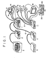
- Fig. 1 is a diagram showing a typical configuration of an AV system to which the present invention is applied.
- the AV system comprises a PC (Personal Computer) module 1, an MPEG1 video deck module 2, a CD-ROM (Compact Disc Read Only Memory) changer module 3, a DVD-ROM (Digital Video Disc Read Only Memory) / movie player module 4 and a device-bay module 5 which are connected to each other by IEEE (Institute of Electrical and Electronics Engineers) 1394 cables 6 referred to hereafter simply as 1394 cables.
- IEEE Institute of Electrical and Electronics Engineers
- the PC module 1 is a personal computer which has only a relatively restricted number of basic functions.
- the MPEG1 video module 2 includes an encoder for generating an image signal conforming to MPEG (Moving Picture Experts Group) 1 specifications, a decoder for decoding such a signal and an embedded hard disc.
- the MPEG1 video module 2 is also provided with a drive unit for driving a video CD, allowing the MPEG1 video module 2 to be used independently as a video CD player.
- the CD-ROM changer module 3 has 100 to 200 pieces of CD-ROM incorporated therein and an embedded drive unit for driving a CD-ROM selected from them.
- an ordinary CD that is, an audio CD By mounting an ordinary CD that is, an audio CD, on the CD-ROM changer player 3, the CD-ROM changer player 3 can be used independently as a CD player.
- the DVD-ROM / movie player module 4 has an embedded drive unit for driving a mounted DVD-ROM in an operation to reproduce data recorded in the DVD-ROM.
- the DVD-ROM / movie player module 4 functions as a DVD player.
- the device-bay module 5 allows a new function to be added by mounting parts which are manufactured in accordance with specifications provided by manufacturers such as Intel (a trade mark) or Compaq (a trade mark).
- the PC module 1 is connected to a monitor 13 and speakers 14 by signal lines 21. Pictures and sound generated by the PC module 1 are displayed and outputted by the monitor 13 and the speakers 14 respectively.
- the PC module 1 is also connected to AV equipment not conforming to IEEE1394 specifications such as a cassette tape deck 15, an MD (Mini Disc) deck 16, a video disc player 17, a television receiver 18, an amplifier 19 and an AV selector module 11.
- the PC module 1 is also capable of controlling these pieces of AV equipment through control lines 12.
- the AV selector module 11 is also connected to each of the cassette tape deck 15, the MD deck 16, the video disc player 17, the television receiver 18 and the amplifier 19 by a signal line 21.
- the AV selector module 11 is capable of selecting one of video or audio signals supplied by the pieces of AV equipment connected thereto and outputting the selected signal to one of the pieces of AV equipment.
- the amplifier 19 is connected to speakers 20 by a signal line 21.
- the cassette tape deck 15 is an apparatus having a tape driving unit and a signal processing unit for recording and playing back a signal to/from a music cassette tape.
- the MD deck 16 is an apparatus having a disk driving unit and an audio signal processing unit for playing back and recording an audio signal from and to an MD (mini disc).
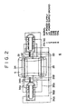
- Fig. 2 is a diagram showing a detailed configuration of the 1394 cable 6.
- the 1394 cable 6 has an outer cylindrical portion 31 and inner cylindrical portions 32 and 33 inside the outer cylindrical portion 31.
- a twisted line 34 comprising wires 34A and 34B is provided inside the inner cylindrical portion 32.
- a twisted line 35 comprising wires 35A and 35B is provided inside the inner cylindrical portion 33.
- the twisted lines 34 and 35 form signal paths which are independent of each other.
- lines 36A and 36B are provided outside the outer cylindrical portion 31 for supplying power.
- the PC module 1 exchanges control, video and audio signals with the AV equipment having functions conforming to IEEE1394 specifications such as the MPEG1 video deck module 2, the CD-ROM changer module 3, the DVD-ROM / movie player module 4 and the device-bay module 5 through the 1394 cables 6.
- Fig. 3 is a diagram showing more detailed interconnection of the control lines 12 and the signal lines 21.
- the PC module 1 is capable of controlling the AV equipment in accordance with three kinds of specifications, i. e., Control S, Control A1 and LANC (Local Application Control Bus System).
- the control lines 12 comprise control lines 12A, 12B and 12C conforming to the Control S, Control A1 and LANC specifications respectively.
- the control lines 12A, 12B and 12C are connected to pieces of AV equipment which conform to their respective specifications.
- the cassette tape deck 15, the AV selector 11 and the television receiver 18 each have a control function based on the Control S specifications.
- the cassette tape deck 15, the AV selector 11 and the television receiver 18 are connected to the PC module 1 by the control line 12A.
- the MD deck 16 and the amplifier 19 each have a control function based on the Contorol A1 specifications.
- the MD deck 16 and the amplifier 19 are connected to the PC module 1 by the control line 12B.
- the video disc player 17 has a control function based on the LANC specifications.
- the video disc player 17 is connected to the PC module 1 by the control line 12C.
- control line 12 can be implemented by only one kind of control line.
- Fig. 4 is a diagram showing a typical internal configuration of the PC module 1.
- the PC module 1 comprises a mother board 41 and an AV interface (I/F) board 42.
- I/F AV interface
- On the mother board 41 a variety of components for implementing a function as a personal computer are mounted.
- the components include a CPU 51 for executing various kinds of processing, a ROM (Read Only Memory) unit 52 for storing constants and programs required by the CPU 51 in the execution of the processing and a RAM (Random Access Memory) unit 53 for storing data required by the CPU 51 in the execution of the processing.
- ROM Read Only Memory
- RAM Random Access Memory
- the mother board 41 is either directly connected to a public telephone line of the PSTN (Public Switched Telephone Network) or provided with a modem 54 which is connected to equipment such as a telephone or a facsimile machine not shown in the figure.
- the modem 54 is used for carrying out communication through the telephone line.
- a video capture unit 55 receives a video signal supplied by the AV selector module 11 and carries out capturing processing on the video signal.
- a TV output unit 56 outputs a video signal from the mother board 41 to the AV selector module 11. For this reasons, the video capture unit 55 and the TV output unit 56 are each connected to the AV selector module 11 by a signal line 21.
- a 1394 interface (I/F) 57 for processing data exchanged through the 1394 cable 6 is connected to the other AV equipment, that is, the MPEG1 video deck module 2 and the DVD-ROM / movie player module 4 in the case of this embodiment, by the 1394 cable 6.
- a graphic accelerator 58 generates graphical data, outputting it to the monitor 13 in order to display the data thereon.
- An audio input/output unit 59 outputs an audio signal generated by the mother board 41 to the speakers 14.
- the AV interface board 42 is connected to a control panel 61 and an IR (Infrared) blaster 62.
- the AV interface board 42 controls the mother board 41 in accordance with a signal received from the control panel 61 or the IR blaster 62.
- Fig. 5 is a diagram showing a detailed configuration of the AV interface board 42.
- the AV interface board 42 includes a microcontroller 71 for executing various kinds of processing in accordance with signals received from a variety of switches provided on the control panel 61.
- the microcontroller 71 also controls operations to turn on and off LEDs provided on the control panel 61.
- An NVRAM (Non-volatile Random Access Memory) unit 72 is used for storing, among other information, data which is also required by the microcontroller 71 even after the power supply is turned off.
- a communication buffer 73 is connected to an ISA (Industry Standard Architecture) used as an extension slot of the mother board 41 or a USB (Universal Serial Bus), a kind of serial bus.
- ISA Industry Standard Architecture
- USB Universal Serial Bus
- the communication buffer 73 is located between the microcontroller 71 and the mother board 41.
- the microcontroller 71 outputs signals conforming to PS/2 (Personal System 2, a trade mark) specifications.
- PS/2 Personal System 2, a trade mark
- the PS/2 specifications are specifications used as an interface for connecting components such as a mouse and a keyboard of a computer to the computer.
- the IR blaster 62 receives an infrared light signal output from an infrared light keyboard (or a radio keyboard) 81 or a remote commander 82, converting the infrared light signal into an electrical signal which is then supplied to the microcontroller 71 by way of a terminal 75 as a KBD signal or an SIRCS (Standard Code for Infrared Remote Control Systems, a trade mark) signal.
- the KBD signal is a signal representing a key code received from the infrared light keyboard 81.
- the microcontroller 71 converts the KBD signal received from the infrared light keyboard 81 to represent a key code into a PS/2 signal described above, transferring the PS/2 signal to the mother board 41.
- the mother board 41 is capable of recognizing the signal received from the infrared light keyboard 81 in the same manner as a signal received from an ordinary keyboard connected by a wire.
- the SIRCS signal is a command signal for controlling AV equipment.
- the microcontroller 71 converts the SIRC signal received from the remote commander 82 into a control signal, that is, a Control-S, Control-Al or LANC control signal, for controlling AV equipment, transferring the control signal to the respective AV equipment through the control line 12. In this way, the microcontroller 71 is capable of controlling the AV equipment connected to the control line 12 in accordance with the control line received from the remote commander 82 for the AV equipment.
- the IR blaster 62 receives a control signal conforming to SIRCS specifications from the microcontroller 71 by way of the terminal 75, converting the control signal into an infrared light signal which is used for controlling AV equipment.
- the AV interface board 42 is located between the mother board 41 and the IR blaster 62, facilitating exchanges of signals conforming to IrDA (Infrared Data Association) specifications between the mother board 41 and the IR blaster 62.
- the mother board 41 transmits data to apparatuses such as another personal computer and AV equipment by using an IrDA signal, a kind of infrared light signal, by way of the IR blaster 62.
- Control signals conforming to the Control-S, Control-A1 and LANC specifications are inputted and outputted from and to the AV interface board 42 through the terminal 74. For this reason, the control lines 12A, 12B and 12C shown in Fig. 3 are connected to the terminal 74.
- Fig. 6 is a diagram showing a typical internal configuration of the DVD-ROM / movie player module 4.
- a CPU 91 executes various kinds of processing in accordance with programs stored in a ROM unit 92.
- a RAM unit 93 is used for properly storing, among other information, data required in the execution of the various kinds of processing by the CPU 91.
- a drive unit 94 drives a DVD-ROM 95.
- a decoder 96 executes processing to decode data reproduced from the DVD-ROM 95.
- a 1394 interface unit 97 executes processing to exchange data with the 1394 cable 6.
- An input/output interface unit 98 is connected to an input unit 99 and an output unit 100.
- a signal representing an input from the input unit 99 is passed on by the input/output interface unit 98 to the CPU 91 while data output by the CPU 91 is forwarded by the input/output interface unit 98 to the output unit 100.
- the input/output interface unit 98 is an interface conforming to the IEEE1394 specifications.
- the DVD-ROM / movie player module 4 is connected to the 1394 serial bus through the input unit 99 and the output unit 100. That is to say, the input unit 99 and the output unit 100 are each connected to the 1394 cable 6
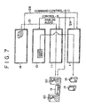
- Figs. 7 and 8 are each a diagram showing an example of this control.
- control to carry out dubbing of a signal reproduced from the MD deck 16 and recorded to the cassette deck 15 and, at the same time, to output sound played back from the MD deck 16 to the speakers 20 is executed.
- the PC module 1 outputs a command conforming to the Control A1 specifications to the MD deck 16 through a control line 12B, requesting that a signal be played back from an MD mounted on the MD deck 16.
- the MD deck 16 reproduces an analog audio signal from the MD mounted thereon, outputting the signal to the AV selector module 11 through a signal line 21.
- the PC module 1 outputs a command conforming to the Control-S specifications to the AV selector module 11 through a control line 12A, requesting the AV selector module 11 that the playback signal received from the MD deck 16 be passed on to the amplifier 19, the cassette tape 15 and the PC module 1 itself.
- the PC module 1 further outputs a command conforming to the Control A1 specifications to the amplifier 19 through a control line 12B, requesting the amplifier 19 that the playback signal passed on thereto by the AV selector module 11 from the MD deck 16 be amplified and the amplified signal be outputted to the speakers 20.
- PC module 1 also outputs a command conforming to the Control S specifications to the cassette tape deck 15 through a control line 12A, requesting the cassette tape deck 15 that the playback signal passed on thereto by the AV selector module 11 from the MD deck 16 be recorded into a cassette tape mounted on the cassette tape deck 15.
- the PC module 1 also outputs the playback signal passed on thereto by the AV selector module 11 from the MD deck 16 to the speakers 14 by way of the audio input/output unit 59 employed in the PC module 1.
- control to display a video signal reproduced by the video disc player 17 on the television receiver 18 and to display images created in the PC module 1 on the monitor 13 is carried out.
- the PC module 1 outputs a command conforming to the LANC specifications to the video disc player 17 through a control line 12C, requesting the video disc player 17 that a video signal be reproduced from a video disc mounted thereon.
- the playback signal is then outputted by the video disc player 17 to the AV selector module through a signal line 21.
- the PC module 1 outputs a command conforming to the Control S specifications to the AV selector module 11 through the control line 12A, requesting the AV selector module 11 that the playback video signal received from the video disc player 17 be passed on to the television receiver 18.
- the PC module 1 outputs a command conforming to the Control S specifications to the television receiver 18 through the control line 12A, controlling the television receiver 18 to display a picture conveyed by the playback video signal passed on thereto by the AV selector module 11 from the video disc player 17.
- the PC module 1 controls the AV selector module 11 through the control line 12A, requesting the AV selector module 11 that the playback video signal received from the video disc player 17 be passed on also to the PC module 1 itself.
- the playback video signal is put in the video picture unit 55 employed there in and, if necessary, mixed with a predetermined image in the graphic accelerator 58 before being outputted to the AV selector module 11 by way of the TV output unit 56.
- the PC module 1 is also capable of having the mixed signal displayed on the television receiver 18.
- the PC module 1 controls the AV selector module 11 through the control line 12A, requesting the AV selector module 11 that the mixed video signal transmitted by the PC module 1 be selected in place of the playback video signal generated by the video disc player 17 and be displayed on the television receiver 18.
- the PC module 1 is also capable of displaying the mixed video signal on the monitor 13.
- the mixed video signal is outputted to the monitor 13 from the graphic accelerator 58.
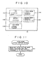
- the flowchart begins with a step S1 at which the CPU 51 employed in the PC module 1 requests AV equipment connected to the PC module 1 by a 1394 cable 6, for example, the DVD-ROM / movie player module 4, that icon picture information of the DVD-ROM /movie player module 4 be transmitted to the PC module 1.
- the DVD-ROM / movie player module 4 has its icon picture data stored in the ROM unit 92 employed therein.
- the icon picture data is picture data for an icon 114 like ones shown in Fig. 10 .
- the CPU 91 employed in the DVD-ROM / movie player module 4 executes processing of a step S11 of a flowchart shown in Fig. 11 to read out the icon picture data stored in the ROM unit 92 and output the data to the 1394 cable 6 by way of the 1394 interface unit 97.
- the icon picture data is put in the 1394 interface unit 57 before being supplied to the CPU 51.
- the CPU 51 receives the incoming icon picture data, storing it in the RAM unit 53.
- the flow of processing then goes on to a step S3 at which the CPU 51 forms a judgment as to whether or not icon picture data has been received from all pieces of AV equipment connected to the PC module 1 by 1394 cables 6. If there is a piece of AV equipment from which the icon picture data thereof has not been received, the flow of processing returns to the step S1 to execute the same processing.
- the PC module 1 also receives pieces of icon picture data 112, 113 and 115 shown in Fig. 10 from the MPEG1 video deck module 2, the CD-ROM changer module 3 and the device-bay module 5 respectively, storing the icon picture data in the RAM module 53.
- the initialization processing is ended.
- the PC module 1 carries out the initialization processing when the power supply of the PC module 1 is turned on in the example described above, the timing with which the initialization processing is carried out is not necessarily the power-on time.
- the CPU 51 employed in the PC module 1 may perform the initialization processing for the AV equipment on a bus connected by 1394 cables 6 to the PC module 1 for every predetermined period based on a program stored in the RAM unit 51 employed in the PC module 1.
- a new piece of electronic equipment can be connected to the bus without turning off the power supply of pieces of electronic equipment already connected to the bus.
- the setting on the bus is reset and initialization processing of the bus (bus reset processing) is carried out.
- the PC module 1 may then execute the initialization processing represented by the flowchart shown in Fig. 9 after knowing that the bus reset processing has been done.
- the PC module 1 is capable of controlling pieces of AV equipment connected thereto without the need to again turn on the power supply of the PC module 1 for a piece of AV equipment which is newly connected to the 1394 serial bus after the power supply of the PC module 1 has been once turned on.
- the flowchart begins with a step S21 at which the user operates, for example, a predetermined key of the infrared light keyboard 81, requesting that a selected screen of AV equipment be displayed.
- a predetermined key of the infrared light keyboard 81 When the predetermined key of the infrared light keyboard 81 is operated, an infrared light signal corresponding to the operated key is outputted by the infrared light keyboard 81 to the IR blaster 62.
- the IR blaster 62 converts the infrared light signal into an electrical signal (a KBD signal), outputting the electrical signal to the microcontroller 71.
- the microcontroller 71 receives the electrical signal which represents the operated key of the infrared light keyboard 81, the microcontroller 71 converts the electrical signal into a PS/2 signal which is then supplied to the CPU 51 employed in the mother board 41.
- the CPU 51 receives out icon picture data from the ROM unit 53 and outputs the data to the graphic accelerator 58.
- the graphic accelerator 58 converts the icon picture data supplied thereto into bit map data, outputting the bit map data to the monitor 13 to be displayed on a screen. In this way, icon pictures 112 to 115 shown in Fig. 10 for example are displayed on the monitor 13 for some AV equipment connected by 1394 cables 6.
- the PC module 1 reads out its own icon picture data stored the ROM unit 52 in advance, displaying the data as an icon picture 111 as shown in Fig. 10 .
- the user specifies a piece of AV equipment to be used by selecting one of the pieces of icon picture data displayed on the screen as shown in Fig. 10 .
- the piece of icon picture data for the desired piece of AV equipment is selected by moving a cursor to point to the piece of icon picture data by operation of a predetermined key on the infrared light keyboard 81.
- a key signal is transmitted to the CPU 51 by way of the IR blaster 62 and the microcontroller 71.
- the CPU 51 enters a state waiting for an icon picture to be selected by the user. As an icon picture is selected, the flow of processing goes on to a step S23.
- the CPU 51 requests the selected AV equipment to transmit display data of operation buttons on the AV equipment to the CPU 51.
- the display data is user interface information required for controlling the AV equipment.
- the CPU 51 issues a command requesting the transmission of the display data to the AV equipment by way of the 1394 interface unit 57 and the 1394 cable 6.
- the CPU 51 requests the DVD-ROM / movie player module 4 to transmit display data of buttons on the DVD-ROM / movie player module 4 required for operations thereof.
- Fig. 13 is a diagram showing typical display data of the DVD-ROM / movie player module 4.
- the DVD-ROM / movie player module 4 outputs the display data of its buttons required for controlling itself to the 1394 cable 6 as requested by the command at a step S31.
- the display data includes picture of buttons, information on the layout of the buttons, a text (strings of characters) explaining the functions of the buttons and a script (program).
- the display data can be described by using a HTML (Hypertext Markup Language) or JavaScript (a trade mark).
- HTML Hypertext Markup Language
- JavaScript a trade mark
- the HTML is a language for describing a format of a document.
- JavaScript is a programming language generally used in a network. Normally, JavaScript is called from a point in a description written in the HTML and used for carrying out predetermined processing specified in a document.
- the CPU 51 employed in the PC module 1 receives, through the 1394 interface module 57, the display data transmitted by the DVD-ROM / movie player interface 4 via the 1394 cable 6 and stores the display data in the RAM unit 53.
- the flow of processing then goes on to a step S25 at which the CPU 51 reads out the display data back from the RAM unit 53, outputting the data to the graphic accelerator 58.
- the graphic data is then converted by the graphic accelerator 58 into bit map data which is finally outputted to the monitor 13 to be displayed thereon.
- buttons required for operating the DVD-ROM / movie player module 4 such as the one shown in Fig. 13 for example is displayed on the monitor 13.
- a string of characters 'DVD-ROM player' appears on the screen as the name of the DVD-ROM /movie player module 4.
- buttons to be operated to request rewind, stop, playback and fast feed operations are displayed.
- buttons to be operated to specify a track are displayed below the operations buttons.
- the flow of processing then goes on to a step S26 at which the CPU 51 employed in the PC module 1 enters a state waiting for one of the buttons shown in Fig. 13 to be operated. The user then selects one of the buttons displayed on the monitor 13 by operating the infrared light keyboard 81.
- the flow of processing proceeds to a step S27 at which the CPU 51 detects the coordinates of the position of the selected button on the monitor 13, that is, information used for recognizing the selected button, and then outputs the positional coordinates to the DVD-ROM / movie player module 4 by way of the 1394 interface unit 57.
- the DVD-ROM / movie player module 4 carries out processing corresponding to the button specified by the positional coordinates at a step S33 of a flowchart shown in Fig. 14 .
- the flowchart begins with a step S31 at which the CPU 91 employed in the DVD-ROM / movie player module 4 receives a command issued by the PC module 1 at the step S23 of the flowchart shown in Fig. 12 through the 1394 interface unit 97.
- the CPU 91 reads out display data of the buttons on the DVD-ROM / movie player module 4 stored in advance in the ROM unit 92 such as the one shown in Fig. 13 and outputs the display data to the PC module 1 by way of the 1394 interface unit 97.
- the PC module 1 receives the display data outputted by the DVD-ROM / movie player module 4 at the step S24 of the flowchart shown in Fig. 12 .
- the PC module 1 then outputs coordinates of the position of an operated one of the buttons shown in Fig. 13 at the step S27 in case the user operates the button also as described earlier.
- the CPU 91 employed in the DVD-ROM / movie player module 4 receives the coordinate data through the 1394 interface unit 97, at a step S32 of the flowchart shown in Fig. 14 , the CPU 91 forms a judgment as to which function the button specified by the received coordinates has. For example, the CPU 91 determines whether the button specified by the coordinates is the playback button, the fast feed button or the rewind button. The flow of processing then goes on to a step S33 at which the CPU 91 carries out processing corresponding to the function identified at the step S32.
- the CPU 91 controls the drive unit 94 to reproduce a signal from the DVD-ROM 95 or, when the fast feed button was judged at the step S32 to have been operated, the CPU 91 puts the CD-ROM 95 in a fast feed state.
- Data reproduced from the DVD-ROM 95 is decoded by the decoder 96 before being outputted to the 1394 cable 6 by way of the 1394 interface unit 97.
- the PC module 1 receives the reproduced data transmitted by the DVD-ROM /movie player module 4 via the 1394 cable 6 through the 1394 interface unit 57, outputting the video data to the graphic accelerator 58 and the audio data to the audio input/output unit 59.
- the graphic accelerator 58 converts the video data supplied thereto into bit map data, outputting the bit map data to the monitor 13 to be displayed thereon.
- the audio input/output unit 59 passes on the audio data supplied thereto to the speakers 14 to be thereby outputted. In this way, the user can enjoy pictures and sound played back from the DVD-ROM 95 by using the monitor 13 and the speakers 14 respectively.
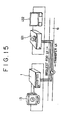
- Fig. 15 is a model diagram showing an operation to read in user interface information of AV equipment connected by a 1394 cable 6 to the PC module 1.
- the AV equipment 121 such as the MPEG1 video deck module 2, the CD-ROM changer module 3, the DVD-ROM / movie player module 4 or the device-bay module 5 shown in Fig. 1 can be used as a stand alone unit or in conjunction with AV equipment 122 independently, that is, without utilizing the PC module 1.
- the user interface information that is, software for controlling the AV equipment 121 from the PC module 1, in the PC module 1.
- the user needs only to connect the AV equipment 121 to the PC module 1 by a 1394 cable 6 and, by merely turning on the power supply, the software installation processing is carried out automatically.
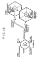
- the PC module 1 can be configured as a computer including only very basic functions. That is to say, the performance level of the PC module 1 in a number of specific applications such as video entertainment, games, multimedia creation, art, graphics, communication and office courses shown in Fig. 16 is low. In comparison with the applications of an all in one personal computer shown in Fig. 17 , the PC module 1 obviously has only very basic functions in each of the applications.
- modules each having an advanced function are purchased and connected to the PC module 1 by 1394 cables 6.
- Examples of such modules are a VAM 1 and a VAM 2 shown in Fig. 16 corresponding to the MPEG1 video module 2, the CD-ROM changer module 3, the DVD-ROM / movie player module 4 and the device-bay module 5 shown in Fig. 1 , corresponding to the MPEG1 video module 2, the CD-ROM changer module 3, the DVD-ROM / movie player module 4 and the device-bay module 5 shown in Fig. 1 .
- the AV equipment can be configured to include embedded user interface information used for controlling the equipment, allowing the designer and/or the manufacturer of the peripheral apparatus, that is, the AV equipment in the case of the present embodiment, to display the originality thereof without being placed under restraint by functions of the PC module 1.
- 1394 cables are employed as a home bus in the embodiment described above, another kind of home bus can also be utilized as well.
- AV equipment is used as peripheral apparatuses in the embodiment as an example. It is worth noting, however, that another kind of electronic equipment can also be employed as well.
- electronic equipment external to the electronic equipment control apparatus is requested to transmit user interface information required for controlling the equipment to the electronic equipment control apparatus.
- the user interface information transmitted in response to the request is then stored in the electronic equipment control apparatus.
- the electronic equipment control apparatus for controlling the electronic equipment is prevented from becoming obsolete only because the apparatus does not have the function for controlling the new electronic equipment.
- user interface information stored in advance in a first piece of electronic equipment can be transferred to a second piece of electronic equipment to be stored therein, allowing a system with an advance function in an application of interest to the user to be implemented at a low cost.
Landscapes
- Engineering & Computer Science (AREA)
- Multimedia (AREA)
- Theoretical Computer Science (AREA)
- Software Systems (AREA)
- General Engineering & Computer Science (AREA)
- Signal Processing (AREA)
- General Physics & Mathematics (AREA)
- Physics & Mathematics (AREA)
- Computer Hardware Design (AREA)
- Computer Security & Cryptography (AREA)
- Computer Networks & Wireless Communication (AREA)
- Selective Calling Equipment (AREA)
- Small-Scale Networks (AREA)
- User Interface Of Digital Computer (AREA)
- Television Signal Processing For Recording (AREA)
Priority Applications (1)
| Application Number | Priority Date | Filing Date | Title |
|---|---|---|---|
| DE69811128T DE69811128T3 (de) | 1997-02-17 | 1998-02-17 | Steuerungsgerät und -methode für elektronische Einrichtung und elektronische Einrichtung |
Applications Claiming Priority (3)
| Application Number | Priority Date | Filing Date | Title |
|---|---|---|---|
| JP03157797A JP3870983B2 (ja) | 1997-02-17 | 1997-02-17 | 電子機器制御装置および方法、並びに電子機器 |
| JP31577/97 | 1997-02-17 | ||
| JP3157797 | 1997-02-17 |
Publications (4)
| Publication Number | Publication Date |
|---|---|
| EP0859306A2 EP0859306A2 (en) | 1998-08-19 |
| EP0859306A3 EP0859306A3 (en) | 1999-06-16 |
| EP0859306B1 EP0859306B1 (en) | 2003-02-05 |
| EP0859306B2 true EP0859306B2 (en) | 2010-06-23 |
Family
ID=12335049
Family Applications (1)
| Application Number | Title | Priority Date | Filing Date |
|---|---|---|---|
| EP98102734A Expired - Lifetime EP0859306B2 (en) | 1997-02-17 | 1998-02-17 | Electronic equipment control apparatus, electronic equipment control method and electronic equipment |
Country Status (6)
| Country | Link |
|---|---|
| US (1) | US6314326B1 (zh) |
| EP (1) | EP0859306B2 (zh) |
| JP (1) | JP3870983B2 (zh) |
| KR (1) | KR19980071395A (zh) |
| DE (1) | DE69811128T3 (zh) |
| TW (1) | TW401544B (zh) |
Cited By (1)
| Publication number | Priority date | Publication date | Assignee | Title |
|---|---|---|---|---|
| US8364295B2 (en) | 2000-10-12 | 2013-01-29 | Bose Corporation | Interactive sound reproducing |
Families Citing this family (80)
| Publication number | Priority date | Publication date | Assignee | Title |
|---|---|---|---|---|
| US10361802B1 (en) | 1999-02-01 | 2019-07-23 | Blanding Hovenweep, Llc | Adaptive pattern recognition based control system and method |
| US8352400B2 (en) | 1991-12-23 | 2013-01-08 | Hoffberg Steven M | Adaptive pattern recognition based controller apparatus and method and human-factored interface therefore |
| US8280682B2 (en) | 2000-12-15 | 2012-10-02 | Tvipr, Llc | Device for monitoring movement of shipped goods |
| JPH11150788A (ja) * | 1997-11-14 | 1999-06-02 | Yamaha Corp | オーディオシステム |
| DE69933637T2 (de) * | 1998-04-22 | 2007-08-23 | Koninklijke Philips Electronics N.V. | Funktionalitätsverwaltung für ein system der unterhaltungselektronik |
| WO1999055070A2 (en) * | 1998-04-22 | 1999-10-28 | Koninklijke Philips Electronics N.V. | Management of functionality in a consumer electronics system |
| US6505255B1 (en) | 1999-04-29 | 2003-01-07 | Mitsubishi Electric Information Technology Center America, Inc. (Ita) | Method for formatting and routing data between an external network and an internal network |
| US6496862B1 (en) | 1998-08-25 | 2002-12-17 | Mitsubishi Electric Research Laboratories, Inc. | Remote monitoring and control of devices connected to an IEEE 1394 bus via a gateway device |
| JP2000090575A (ja) * | 1998-09-14 | 2000-03-31 | Toshiba Corp | ネットワーク統合管理装置及び方法 |
| DE19901822A1 (de) * | 1999-01-19 | 2000-07-20 | Alcatel Sa | Verfahren zum Bedienen einer Kombination von Geräten der Unterhaltungselektronik |
| US7904187B2 (en) | 1999-02-01 | 2011-03-08 | Hoffberg Steven M | Internet appliance system and method |
| US6523064B1 (en) | 1999-04-29 | 2003-02-18 | Mitsubishi Electric Research Laboratories, Inc | Network gateway for collecting geographic data information |
| US6633547B1 (en) | 1999-04-29 | 2003-10-14 | Mitsubishi Electric Research Laboratories, Inc. | Command and control transfer |
| US6378000B1 (en) | 1999-04-29 | 2002-04-23 | Mitsubish Electric Research Laboratories, Inc | Address mapping in home entertainment network |
| JP4313894B2 (ja) * | 1999-06-01 | 2009-08-12 | キヤノン株式会社 | 通信システム及び被制御装置 |
| US20060245741A1 (en) * | 2000-03-09 | 2006-11-02 | Cynthia Lakhansingh | Digital enterainment recorder |
| JP4635290B2 (ja) * | 2000-03-16 | 2011-02-23 | ソニー株式会社 | 制御方法及び表示装置 |
| US7187947B1 (en) | 2000-03-28 | 2007-03-06 | Affinity Labs, Llc | System and method for communicating selected information to an electronic device |
| JP4041862B2 (ja) * | 2000-04-05 | 2008-02-06 | 孝 前島 | インターネット利用遊技システム |
| KR100694043B1 (ko) * | 2000-05-18 | 2007-03-12 | 삼성전자주식회사 | Av 시스템 및 그 기능 확장 모듈 |
| WO2002019104A1 (fr) * | 2000-08-28 | 2002-03-07 | Sony Corporation | Dispositif et procede de communication, systeme de reseau et appareil robotise |
| DE10145708B4 (de) * | 2000-09-19 | 2007-02-01 | Samsung Electronics Co., Ltd., Suwon | Vorrichtung und Verfahren zum Verbinden eines Basismoduls mit einem Funktionserweiterungsmodul in einem AV-System |
| US7146260B2 (en) | 2001-04-24 | 2006-12-05 | Medius, Inc. | Method and apparatus for dynamic configuration of multiprocessor system |
| US10298735B2 (en) | 2001-04-24 | 2019-05-21 | Northwater Intellectual Property Fund L.P. 2 | Method and apparatus for dynamic configuration of a multiprocessor health data system |
| US6930730B2 (en) * | 2001-05-03 | 2005-08-16 | Mitsubishi Digital Electronics America, Inc. | Control system and user interface for network of input devices |
| CA2463922C (en) | 2001-06-27 | 2013-07-16 | 4 Media, Inc. | Improved media delivery platform |
| DE20201726U1 (de) * | 2002-02-05 | 2002-04-11 | Hsing Chau Ind Co | Anschlußadapter für Videographik-Beschleunigerkarten |
| US8131389B1 (en) * | 2002-02-08 | 2012-03-06 | Digital Voice Systems, Inc. | Digital audio server |
| US6914551B2 (en) * | 2002-04-12 | 2005-07-05 | Apple Computer, Inc. | Apparatus and method to facilitate universal remote control |
| US7178049B2 (en) | 2002-04-24 | 2007-02-13 | Medius, Inc. | Method for multi-tasking multiple Java virtual machines in a secure environment |
| JP4693363B2 (ja) | 2003-05-28 | 2011-06-01 | キヤノン株式会社 | テレビジョン装置及びその制御方法 |
| US20050030386A1 (en) * | 2003-08-04 | 2005-02-10 | John Kamieniecki | Method and apparatus for determining video formats supported by a digital television receiver |
| DE10339123A1 (de) * | 2003-08-22 | 2004-12-23 | Loewe Opta Gmbh | Verfahren zum Betreiben von vernetzten Rundfunkgeräten |
| US9654554B2 (en) * | 2003-09-12 | 2017-05-16 | Seagate Technology Llc | Seamless scaling of multiple appliances |
| US20050216944A1 (en) * | 2004-03-24 | 2005-09-29 | Johnson Dan S | Audio/video component networking system and method |
| US20050273657A1 (en) * | 2004-04-01 | 2005-12-08 | Hiroshi Ichiki | Information processing apparatus and method, and recording medium and program for controlling the same |
| US7441062B2 (en) | 2004-04-27 | 2008-10-21 | Apple Inc. | Connector interface system for enabling data communication with a multi-communication device |
| US7526588B1 (en) | 2004-04-27 | 2009-04-28 | Apple Inc. | Communication between an accessory and a media player using a protocol with multiple lingoes |
| US7529870B1 (en) | 2004-04-27 | 2009-05-05 | Apple Inc. | Communication between an accessory and a media player with multiple lingoes |
| US8117651B2 (en) | 2004-04-27 | 2012-02-14 | Apple Inc. | Method and system for authenticating an accessory |
| US7673083B2 (en) * | 2004-04-27 | 2010-03-02 | Apple Inc. | Method and system for controlling video selection and playback in a portable media player |
| US7529872B1 (en) | 2004-04-27 | 2009-05-05 | Apple Inc. | Communication between an accessory and a media player using a protocol with multiple lingoes |
| KR100602206B1 (ko) * | 2004-06-18 | 2006-07-19 | 삼성전자주식회사 | Scart 커넥터를 구비한 복합장치 및 그 제어 방법 |
| US7337650B1 (en) | 2004-11-09 | 2008-03-04 | Medius Inc. | System and method for aligning sensors on a vehicle |
| US7823214B2 (en) | 2005-01-07 | 2010-10-26 | Apple Inc. | Accessory authentication for electronic devices |
| DE102005003393B4 (de) * | 2005-01-24 | 2007-01-18 | Loewe Opta Gmbh | Verfahren zur automatischen Auswahl von mindestens einem elektronischen Informations- und/oder Kommunikationsgerät und/oder einer Gerätekomponente |
| DE102005040924B3 (de) * | 2005-08-30 | 2006-11-30 | Loewe Opta Gmbh | Verfahren zur Bereitstellung einer Bedienoberfläche zur Auswahl mindestens eines elektronischen Informations- und/oder Kommunikationsgerätes |
| KR101053852B1 (ko) * | 2006-03-10 | 2011-08-03 | 삼성전자주식회사 | 거치장치, 휴대용 단말기 및 그 제어방법 |
| US7509402B2 (en) | 2006-03-16 | 2009-03-24 | Exceptional Innovation, Llc | Automation control system having a configuration tool and two-way ethernet communication for web service messaging, discovery, description, and eventing that is controllable with a touch-screen display |
| US7496627B2 (en) | 2006-03-16 | 2009-02-24 | Exceptional Innovation, Llc | Automation control system having digital logging |
| US7587464B2 (en) | 2006-03-16 | 2009-09-08 | Exceptional Innovation, Llc | Device automation using networked device control having a web services for devices stack |
| US8725845B2 (en) | 2006-03-16 | 2014-05-13 | Exceptional Innovation Llc | Automation control system having a configuration tool |
| US8209398B2 (en) | 2006-03-16 | 2012-06-26 | Exceptional Innovation Llc | Internet protocol based media streaming solution |
| US7966083B2 (en) | 2006-03-16 | 2011-06-21 | Exceptional Innovation Llc | Automation control system having device scripting |
| US8001219B2 (en) | 2006-03-16 | 2011-08-16 | Exceptional Innovation, Llc | User control interface for convergence and automation system |
| US8155142B2 (en) | 2006-03-16 | 2012-04-10 | Exceptional Innovation Llc | Network based digital access point device |
| WO2007126781A2 (en) | 2006-03-27 | 2007-11-08 | Exceptional Innovation Llc | Set top box for convergence and automation system |
| WO2007124453A2 (en) | 2006-04-20 | 2007-11-01 | Exceptional Innovation Llc | Touch screen for convergence and automation system |
| US7667968B2 (en) | 2006-05-19 | 2010-02-23 | Exceptional Innovation, Llc | Air-cooling system configuration for touch screen |
| US8073984B2 (en) | 2006-05-22 | 2011-12-06 | Apple Inc. | Communication protocol for use with portable electronic devices |
| US7643895B2 (en) | 2006-05-22 | 2010-01-05 | Apple Inc. | Portable media device with workout support |
| US20070271116A1 (en) | 2006-05-22 | 2007-11-22 | Apple Computer, Inc. | Integrated media jukebox and physiologic data handling application |
| US7415563B1 (en) | 2006-06-27 | 2008-08-19 | Apple Inc. | Method and system for allowing a media player to determine if it supports the capabilities of an accessory |
| US7558894B1 (en) | 2006-09-11 | 2009-07-07 | Apple Inc. | Method and system for controlling power provided to an accessory |
| JP4588005B2 (ja) * | 2006-09-14 | 2010-11-24 | シャープ株式会社 | 通信端末装置、映像表示装置および制御プログラム |
| US8806562B2 (en) | 2006-10-27 | 2014-08-12 | Hewlett-Packard Development Company, L.P. | Audio/video component networking system and method |
| WO2008073658A2 (en) | 2006-11-09 | 2008-06-19 | Exceptional Innovation, Llc. | Portable device for convergence and automation solution |
| KR101446939B1 (ko) * | 2007-03-30 | 2014-10-06 | 삼성전자주식회사 | 원격 제어 장치 및 그 제어 방법 |
| US20090094539A1 (en) * | 2007-08-29 | 2009-04-09 | Yao-Tian Wang | Controlling a computer peripheral device using a universal driver and device-generated user interface information |
| US20090156251A1 (en) * | 2007-12-12 | 2009-06-18 | Alan Cannistraro | Remote control protocol for media systems controlled by portable devices |
| JP5036630B2 (ja) * | 2008-05-29 | 2012-09-26 | シャープ株式会社 | ネットワークシステム、通信方法、および通信端末 |
| US9716774B2 (en) | 2008-07-10 | 2017-07-25 | Apple Inc. | System and method for syncing a user interface on a server device to a user interface on a client device |
| US8238811B2 (en) | 2008-09-08 | 2012-08-07 | Apple Inc. | Cross-transport authentication |
| US8208853B2 (en) | 2008-09-08 | 2012-06-26 | Apple Inc. | Accessory device authentication |
| US9358924B1 (en) | 2009-05-08 | 2016-06-07 | Eagle Harbor Holdings, Llc | System and method for modeling advanced automotive safety systems |
| US8417490B1 (en) | 2009-05-11 | 2013-04-09 | Eagle Harbor Holdings, Llc | System and method for the configuration of an automotive vehicle with modeled sensors |
| CN101902605A (zh) * | 2009-06-01 | 2010-12-01 | 海尔集团公司 | 电视机信号转接盒及其控制方法 |
| US9107040B2 (en) | 2010-09-29 | 2015-08-11 | Apple Inc. | Systems, methods, and computer readable media for sharing awareness information |
| US8886392B1 (en) | 2011-12-21 | 2014-11-11 | Intellectual Ventures Fund 79 Llc | Methods, devices, and mediums associated with managing vehicle maintenance activities |
| US10214933B2 (en) | 2017-05-11 | 2019-02-26 | Hayward Industries, Inc. | Pool cleaner power supply |
Family Cites Families (41)
| Publication number | Priority date | Publication date | Assignee | Title |
|---|---|---|---|---|
| DE3151492A1 (de) | 1981-11-21 | 1983-07-07 | Gorenje Körting Electronic GmbH & Co, 8217 Grassau | Audio-video-heimanlage |
| JPS60160491A (ja) | 1984-01-31 | 1985-08-22 | Toshiba Corp | Icカードとicカード発行装置 |
| US4652874A (en) | 1984-12-24 | 1987-03-24 | Motorola, Inc. | Serial communication interface for a local network controller |
| US4723120A (en) | 1986-01-14 | 1988-02-02 | International Business Machines Corporation | Method and apparatus for constructing and operating multipoint communication networks utilizing point-to point hardware and interfaces |
| US4903016A (en) | 1987-07-07 | 1990-02-20 | Ricoh Company, Ltd. | Communication control unit |
| US5007051A (en) | 1987-09-30 | 1991-04-09 | Hewlett-Packard Company | Link layer protocol and apparatus for data communication |
| JP2751270B2 (ja) | 1988-11-29 | 1998-05-18 | 松下電器産業株式会社 | Avtcシステム |
| US5400246A (en) * | 1989-05-09 | 1995-03-21 | Ansan Industries, Ltd. | Peripheral data acquisition, monitor, and adaptive control system via personal computer |
| DE69130875T2 (de) | 1990-07-19 | 1999-06-10 | Sony Corp | Verfahren zur Aufstellung von Adressen für elektronische Geräte |
| US5539390A (en) | 1990-07-19 | 1996-07-23 | Sony Corporation | Method for setting addresses for series-connectd apparatuses |
| JPH0497468A (ja) | 1990-08-16 | 1992-03-30 | Canon Inc | 画像処理システム |
| US5850573A (en) | 1990-08-16 | 1998-12-15 | Canon Kabushiki Kaisha | Control method for peripheral device in host computer connectable to a plurality of peripheral devices |
| FR2671884A1 (fr) | 1991-01-17 | 1992-07-24 | Moulinex Sa | Procede d'attribution d'adresses dans un reseau domotique. |
| JP3128141B2 (ja) * | 1991-03-19 | 2001-01-29 | パイオニア株式会社 | システムコントローラ |
| JP3063253B2 (ja) | 1991-07-06 | 2000-07-12 | ソニー株式会社 | オーディオまたはビデオ機器の制御システムおよび方法 |
| US5875108A (en) * | 1991-12-23 | 1999-02-23 | Hoffberg; Steven M. | Ergonomic man-machine interface incorporating adaptive pattern recognition based control system |
| CA2091851A1 (en) | 1992-03-25 | 1993-09-26 | Michael J. Sherman | Link layered communications network and method |
| JP3144049B2 (ja) | 1992-04-24 | 2001-03-07 | ソニー株式会社 | Av機器の編集制御方法 |
| US5404544A (en) | 1992-06-05 | 1995-04-04 | Advanced Micro Devices | System for periodically transmitting signal to/from sleeping node identifying its existence to a network and awakening the sleeping node responding to received instruction |
| GB2268816B (en) | 1992-07-14 | 1996-01-17 | Sony Broadcast & Communication | Controlling equipment |
| US5410326A (en) * | 1992-12-04 | 1995-04-25 | Goldstein; Steven W. | Programmable remote control device for interacting with a plurality of remotely controlled devices |
| US5475835A (en) * | 1993-03-02 | 1995-12-12 | Research Design & Marketing Inc. | Audio-visual inventory and play-back control system |
| DE69432199T2 (de) | 1993-05-24 | 2004-01-08 | Sun Microsystems, Inc., Mountain View | Graphische Benutzerschnittstelle mit Verfahren zur Schnittstellebildung mit fernsteuernden Einrichtungen |
| CN100545828C (zh) | 1993-07-30 | 2009-09-30 | 佳能株式会社 | 控制连接到网络的网络设备的控制设备及其控制方法 |
| JPH07134628A (ja) | 1993-11-10 | 1995-05-23 | Hitachi Ltd | 省電力制御方法および情報処理装置 |
| JPH0845255A (ja) | 1994-08-03 | 1996-02-16 | Sony Corp | オーディオビデオシステムの制御方法 |
| WO1996007971A1 (en) | 1994-09-09 | 1996-03-14 | Medialink Technologies Corporation | Method and apparatus for automatically configuring an interface |
| US5657221A (en) | 1994-09-16 | 1997-08-12 | Medialink Technologies Corporation | Method and apparatus for controlling non-computer system devices by manipulating a graphical representation |
| JP3617105B2 (ja) | 1995-02-16 | 2005-02-02 | ソニー株式会社 | 電子機器及びその動作モード制御方法 |
| JP3617115B2 (ja) | 1995-03-31 | 2005-02-02 | ソニー株式会社 | ビデオ信号処理装置および処理方法 |
| US5687334A (en) | 1995-05-08 | 1997-11-11 | Apple Computer, Inc. | User interface for configuring input and output devices of a computer |
| US5900867A (en) * | 1995-07-17 | 1999-05-04 | Gateway 2000, Inc. | Self identifying remote control device having a television receiver for use in a computer |
| US5787259A (en) | 1996-03-29 | 1998-07-28 | Microsoft Corporation | Digital interconnects of a PC with consumer electronics devices |
| US5793366A (en) | 1996-11-12 | 1998-08-11 | Sony Corporation | Graphical display of an animated data stream between devices on a bus |
| EP0860823A4 (en) | 1996-07-15 | 2001-05-02 | Toshiba Kk | DEVICE WITH DIGITAL INTERFACE, NETWORK SYSTEM WITH THIS DEVICE AND COPY PROTECTION PROCEDURE |
| US5847771A (en) | 1996-08-14 | 1998-12-08 | Bell Atlantic Network Services, Inc. | Digital entertainment terminal providing multiple digital pictures |
| US5922047A (en) * | 1996-10-22 | 1999-07-13 | Motorola, Inc. | Apparatus, method and system for multimedia control and communication |
| JPH10145753A (ja) | 1996-11-15 | 1998-05-29 | Sony Corp | 受信装置および方法 |
| US5963450A (en) * | 1996-12-20 | 1999-10-05 | Square D Company | Operator interface unit for monitoring and controlling devices having dissimilar data structures |
| US5877821A (en) * | 1997-01-30 | 1999-03-02 | Motorola, Inc. | Multimedia input and control apparatus and method for multimedia communications |
| US5887573A (en) | 1997-06-25 | 1999-03-30 | Stanadyne Automotive Corp. | Fuel filter with cold start circuit |
-
1997
- 1997-02-17 JP JP03157797A patent/JP3870983B2/ja not_active Expired - Lifetime
-
1998
- 1998-02-09 US US09/020,730 patent/US6314326B1/en not_active Expired - Lifetime
- 1998-02-10 TW TW087101787A patent/TW401544B/zh not_active IP Right Cessation
- 1998-02-17 KR KR1019980004683A patent/KR19980071395A/ko active Search and Examination
- 1998-02-17 EP EP98102734A patent/EP0859306B2/en not_active Expired - Lifetime
- 1998-02-17 DE DE69811128T patent/DE69811128T3/de not_active Expired - Lifetime
Cited By (4)
| Publication number | Priority date | Publication date | Assignee | Title |
|---|---|---|---|---|
| US8364295B2 (en) | 2000-10-12 | 2013-01-29 | Bose Corporation | Interactive sound reproducing |
| US8401682B2 (en) | 2000-10-12 | 2013-03-19 | Bose Corporation | Interactive sound reproducing |
| US8977375B2 (en) | 2000-10-12 | 2015-03-10 | Bose Corporation | Interactive sound reproducing |
| US9223538B2 (en) | 2000-10-12 | 2015-12-29 | Bose Corporation | Interactive sound reproducing |
Also Published As
| Publication number | Publication date |
|---|---|
| DE69811128D1 (de) | 2003-03-13 |
| DE69811128T2 (de) | 2003-11-06 |
| TW401544B (en) | 2000-08-11 |
| EP0859306B1 (en) | 2003-02-05 |
| DE69811128T3 (de) | 2011-07-07 |
| US6314326B1 (en) | 2001-11-06 |
| JPH10229409A (ja) | 1998-08-25 |
| EP0859306A2 (en) | 1998-08-19 |
| EP0859306A3 (en) | 1999-06-16 |
| JP3870983B2 (ja) | 2007-01-24 |
| KR19980071395A (ko) | 1998-10-26 |
Similar Documents
| Publication | Publication Date | Title |
|---|---|---|
| EP0859306B2 (en) | Electronic equipment control apparatus, electronic equipment control method and electronic equipment | |
| KR100617882B1 (ko) | 전자기기제어장치및방법,및전자기기제어시스템및전자기기 | |
| JP3746474B2 (ja) | モジュール化したリモートコントローラ | |
| US6466233B1 (en) | Information processing unit for controlling a plurality of electronic devices and method thereof, and provision medium associated therewith | |
| KR200287395Y1 (ko) | 여러 종류의 메모리 카드를 지원하는 미디어 플레이어 | |
| CN101480019B (zh) | 本地用户界面与远程生成的用户界面和媒体的合成 | |
| US20150019783A1 (en) | System and method for accessing a user interface via a secondary device | |
| KR20090015926A (ko) | 원격 제어가능한 미디어 분포 디바이스 | |
| US20020008779A1 (en) | Audio/video system and function-extending module therefor | |
| US9009776B2 (en) | Information processing apparatus and output control method | |
| US7685324B2 (en) | Audio-video processing apparatus and program therefor | |
| JPH09149325A (ja) | グラフイック表示データ分散型avシステム | |
| US20020055278A1 (en) | Apparatus and method for connecting base module and function-extending module in AV system | |
| US7406570B2 (en) | Multisystem network, and device and method for access to data storage | |
| US20090044221A1 (en) | Information Processing Apparatus and Program Startup Control Method | |
| US20090157910A1 (en) | Information playback apparatus and information playback method | |
| JP4427756B2 (ja) | 電子機器制御装置および方法、並びに電子機器 | |
| WO2012172850A1 (ja) | 機器操作システム、表示機器、及び操作機器 | |
| US20060064525A1 (en) | Remote control unit with a computer peripheral communication port | |
| JP2007097095A (ja) | Avシステム及びその制御方法 | |
| JP2005223632A (ja) | 記録映像表示装置、記録映像表示方法及び記録映像表示システム | |
| KR100536839B1 (ko) | 복수 메뉴 디스플레이 영상 기록/재생 장치 및 그 표시방법 | |
| US7895610B1 (en) | System and method for displaying information on the screen of a user interface device under the control of a digital audio playback device | |
| JPH10290487A (ja) | リモートコントローラ、リモートコントローラ制御方法、および、媒体 | |
| JP2001228954A (ja) | 外部連結機器に対する映像機器のメニュー遠隔制御方法 |
Legal Events
| Date | Code | Title | Description |
|---|---|---|---|
| PUAI | Public reference made under article 153(3) epc to a published international application that has entered the european phase |
Free format text: ORIGINAL CODE: 0009012 |
|
| AK | Designated contracting states |
Kind code of ref document: A2 Designated state(s): DE FR GB |
|
| AX | Request for extension of the european patent |
Free format text: AL;LT;LV;MK;RO;SI |
|
| PUAL | Search report despatched |
Free format text: ORIGINAL CODE: 0009013 |
|
| AK | Designated contracting states |
Kind code of ref document: A3 Designated state(s): AT BE CH DE DK ES FI FR GB GR IE IT LI LU MC NL PT SE |
|
| AX | Request for extension of the european patent |
Free format text: AL;LT;LV;MK;RO;SI |
|
| 17P | Request for examination filed |
Effective date: 19991018 |
|
| AKX | Designation fees paid |
Free format text: DE FR GB |
|
| 17Q | First examination report despatched |
Effective date: 20010521 |
|
| GRAG | Despatch of communication of intention to grant |
Free format text: ORIGINAL CODE: EPIDOS AGRA |
|
| GRAG | Despatch of communication of intention to grant |
Free format text: ORIGINAL CODE: EPIDOS AGRA |
|
| GRAH | Despatch of communication of intention to grant a patent |
Free format text: ORIGINAL CODE: EPIDOS IGRA |
|
| GRAH | Despatch of communication of intention to grant a patent |
Free format text: ORIGINAL CODE: EPIDOS IGRA |
|
| GRAA | (expected) grant |
Free format text: ORIGINAL CODE: 0009210 |
|
| AK | Designated contracting states |
Designated state(s): DE FR GB |
|
| REG | Reference to a national code |
Ref country code: GB Ref legal event code: FG4D |
|
| REF | Corresponds to: |
Ref document number: 69811128 Country of ref document: DE Date of ref document: 20030313 Kind code of ref document: P |
|
| ET | Fr: translation filed | ||
| PLBQ | Unpublished change to opponent data |
Free format text: ORIGINAL CODE: EPIDOS OPPO |
|
| PLBI | Opposition filed |
Free format text: ORIGINAL CODE: 0009260 |
|
| PLAX | Notice of opposition and request to file observation + time limit sent |
Free format text: ORIGINAL CODE: EPIDOSNOBS2 |
|
| 26 | Opposition filed |
Opponent name: INTERESSENGEMEINSCHAFTFUER RUNDFUNKSCHUTZRECHTE E. Effective date: 20031105 |
|
| PLBB | Reply of patent proprietor to notice(s) of opposition received |
Free format text: ORIGINAL CODE: EPIDOSNOBS3 |
|
| PLAY | Examination report in opposition despatched + time limit |
Free format text: ORIGINAL CODE: EPIDOSNORE2 |
|
| PLBC | Reply to examination report in opposition received |
Free format text: ORIGINAL CODE: EPIDOSNORE3 |
|
| PLCK | Communication despatched that opposition was rejected |
Free format text: ORIGINAL CODE: EPIDOSNREJ1 |
|
| APBP | Date of receipt of notice of appeal recorded |
Free format text: ORIGINAL CODE: EPIDOSNNOA2O |
|
| APAH | Appeal reference modified |
Free format text: ORIGINAL CODE: EPIDOSCREFNO |
|
| APBQ | Date of receipt of statement of grounds of appeal recorded |
Free format text: ORIGINAL CODE: EPIDOSNNOA3O |
|
| APAH | Appeal reference modified |
Free format text: ORIGINAL CODE: EPIDOSCREFNO |
|
| APBU | Appeal procedure closed |
Free format text: ORIGINAL CODE: EPIDOSNNOA9O |
|
| PLAY | Examination report in opposition despatched + time limit |
Free format text: ORIGINAL CODE: EPIDOSNORE2 |
|
| PUAH | Patent maintained in amended form |
Free format text: ORIGINAL CODE: 0009272 |
|
| STAA | Information on the status of an ep patent application or granted ep patent |
Free format text: STATUS: PATENT MAINTAINED AS AMENDED |
|
| 27A | Patent maintained in amended form |
Effective date: 20100623 |
|
| AK | Designated contracting states |
Kind code of ref document: B2 Designated state(s): DE FR GB |
|
| PG25 | Lapsed in a contracting state [announced via postgrant information from national office to epo] |
Ref country code: DE Free format text: LAPSE BECAUSE OF FAILURE TO SUBMIT A TRANSLATION OF THE DESCRIPTION OR TO PAY THE FEE WITHIN THE PRESCRIBED TIME-LIMIT Effective date: 20100924 |
|
| REG | Reference to a national code |
Ref country code: DE Ref legal event code: 8570 |
|
| REG | Reference to a national code |
Ref country code: FR Ref legal event code: PLFP Year of fee payment: 19 |
|
| REG | Reference to a national code |
Ref country code: FR Ref legal event code: PLFP Year of fee payment: 20 |
|
| PGFP | Annual fee paid to national office [announced via postgrant information from national office to epo] |
Ref country code: DE Payment date: 20170217 Year of fee payment: 20 Ref country code: FR Payment date: 20170217 Year of fee payment: 20 |
|
| PGFP | Annual fee paid to national office [announced via postgrant information from national office to epo] |
Ref country code: GB Payment date: 20170216 Year of fee payment: 20 |
|
| REG | Reference to a national code |
Ref country code: DE Ref legal event code: R071 Ref document number: 69811128 Country of ref document: DE |
|
| REG | Reference to a national code |
Ref country code: GB Ref legal event code: PE20 Expiry date: 20180216 |
|
| PG25 | Lapsed in a contracting state [announced via postgrant information from national office to epo] |
Ref country code: GB Free format text: LAPSE BECAUSE OF EXPIRATION OF PROTECTION Effective date: 20180216 |