EP0858495B1 - Verwendung eines verfahrens zum betreiben einer verbrennungsanlage eines kohlekraftwerkes zur beschleunigung des kohleausbrendes einer schmelzkammer - Google Patents
Verwendung eines verfahrens zum betreiben einer verbrennungsanlage eines kohlekraftwerkes zur beschleunigung des kohleausbrendes einer schmelzkammer Download PDFInfo
- Publication number
- EP0858495B1 EP0858495B1 EP96929184A EP96929184A EP0858495B1 EP 0858495 B1 EP0858495 B1 EP 0858495B1 EP 96929184 A EP96929184 A EP 96929184A EP 96929184 A EP96929184 A EP 96929184A EP 0858495 B1 EP0858495 B1 EP 0858495B1
- Authority
- EP
- European Patent Office
- Prior art keywords
- coal
- titanium dioxide
- containing material
- combustion
- use according
- Prior art date
- Legal status (The legal status is an assumption and is not a legal conclusion. Google has not performed a legal analysis and makes no representation as to the accuracy of the status listed.)
- Expired - Lifetime
Links
Images

Classifications
-
- C—CHEMISTRY; METALLURGY
- C10—PETROLEUM, GAS OR COKE INDUSTRIES; TECHNICAL GASES CONTAINING CARBON MONOXIDE; FUELS; LUBRICANTS; PEAT
- C10L—FUELS NOT OTHERWISE PROVIDED FOR; NATURAL GAS; SYNTHETIC NATURAL GAS OBTAINED BY PROCESSES NOT COVERED BY SUBCLASSES C10G OR C10K; LIQUIFIED PETROLEUM GAS; USE OF ADDITIVES TO FUELS OR FIRES; FIRE-LIGHTERS
- C10L9/00—Treating solid fuels to improve their combustion
- C10L9/10—Treating solid fuels to improve their combustion by using additives
-
- F—MECHANICAL ENGINEERING; LIGHTING; HEATING; WEAPONS; BLASTING
- F23—COMBUSTION APPARATUS; COMBUSTION PROCESSES
- F23J—REMOVAL OR TREATMENT OF COMBUSTION PRODUCTS OR COMBUSTION RESIDUES; FLUES
- F23J7/00—Arrangement of devices for supplying chemicals to fire
-
- C—CHEMISTRY; METALLURGY
- C10—PETROLEUM, GAS OR COKE INDUSTRIES; TECHNICAL GASES CONTAINING CARBON MONOXIDE; FUELS; LUBRICANTS; PEAT
- C10L—FUELS NOT OTHERWISE PROVIDED FOR; NATURAL GAS; SYNTHETIC NATURAL GAS OBTAINED BY PROCESSES NOT COVERED BY SUBCLASSES C10G OR C10K; LIQUIFIED PETROLEUM GAS; USE OF ADDITIVES TO FUELS OR FIRES; FIRE-LIGHTERS
- C10L10/00—Use of additives to fuels or fires for particular purposes
- C10L10/02—Use of additives to fuels or fires for particular purposes for reducing smoke development
-
- F—MECHANICAL ENGINEERING; LIGHTING; HEATING; WEAPONS; BLASTING
- F23—COMBUSTION APPARATUS; COMBUSTION PROCESSES
- F23B—METHODS OR APPARATUS FOR COMBUSTION USING ONLY SOLID FUEL
- F23B5/00—Combustion apparatus with arrangements for burning uncombusted material from primary combustion
- F23B5/02—Combustion apparatus with arrangements for burning uncombusted material from primary combustion in main combustion chamber
-
- Y—GENERAL TAGGING OF NEW TECHNOLOGICAL DEVELOPMENTS; GENERAL TAGGING OF CROSS-SECTIONAL TECHNOLOGIES SPANNING OVER SEVERAL SECTIONS OF THE IPC; TECHNICAL SUBJECTS COVERED BY FORMER USPC CROSS-REFERENCE ART COLLECTIONS [XRACs] AND DIGESTS
- Y10—TECHNICAL SUBJECTS COVERED BY FORMER USPC
- Y10S—TECHNICAL SUBJECTS COVERED BY FORMER USPC CROSS-REFERENCE ART COLLECTIONS [XRACs] AND DIGESTS
- Y10S44/00—Fuel and related compositions
- Y10S44/905—Method involving added catalyst
Definitions
- the invention relates to the use of a method for operating a combustion plant of a coal-fired power plant with smelting chamber firing.
- the combustion temperature in the combustion chamber which in this case is also referred to as the melting chamber, is above the melting temperature of the ash. Under normal operating conditions, this is approx. 1500 ° C.
- the ash melting temperature of the coal used for firing can vary widely and is essentially dependent on the content of aluminum oxide Al 2 O 3 and silicate SiO 2 .
- the majority of the ashes combine to form a melt flow at the bottom of the combustion chamber and are supplied to wet slag removers below through outlet openings. These are pools of water in which the leaking liquid ash is caught and quenched.
- the granulate is a popular material in road construction and is used, for example, as a bulk material but also as a grit or blasting agent.
- the fly ash entrained by the flue gas flow which can consist of up to 50% combustible material (carbon and / or semi-burned hydrocarbons), is separated in the electrostatic precipitators.
- the temperature of the combustion or melting chamber and the melting temperature of the ash must be coordinated for particularly effective melting chamber operation, ie complete burnout, rapid fuel conversion and avoidance of NO x formation.
- the composition of the coal (depending on the composition, the ash melting temperature varies between 1300 ° C and 1700 ° C) determines the design of the coal-fired power plant, such as the size of the combustion chamber. By adding limestone, however, it is possible to lower the melting temperature of the ash. Experience shows that by adding approx. 2% limestone to coal, the melting temperature of the ash can be reduced by approx. 100 ° C. This procedure provides a regulation for the operation of the furnace.
- the fly ash return makes it a perfect one Burnout of the fuel achieved, however, the increases average residence time of a coal or ash particle in the Feuerungsniklauf.
- the disadvantage is the maximum Throughput of coal and thus the possible performance of the Power plant limited.
- the invention is therefore based on the object of an inexpensive Method for operating a coal-fired power plant, which according to the process of melting chamber firing works, with which the throughput of fuel and thus the performance of the power plant can be increased.
- This is supposed to be with a incinerator suitable for carrying out the method can be achieved with particularly simple means.
- Titanium dioxide at most in a titanium dioxide: coal ratio of 3:97.
- the invention is based on the observation that titanium dioxide the burning out of the coal in the combustion chamber and thus can increase the throughput of coal, which in turn Performance increase of the power plant leads.
- the viscosity and the melting temperature of the ash is not essential to be changed.
- the addition of titanium the is present as titanium dioxide under the conditions of the melting chamber, slag-like approaches behind the combustion chamber, that stick to pipes and walls, do not favor. It has been shown that titanium dioxide has the melting point of Ash or slag lowers. From a sand-like, not melted and non-sticking dust could result in a viscous, flowing and sticky melt become the higher Cleaning costs and financial losses during maintenance of the coal-fired power plant. However, it was found that the titanium dioxide is largely found in the liquid ash.
- the titanium dioxide content is in the total amount of coal and materials containing titanium dioxide added at most 2.25%.
- titanium dioxide content is also lower in the mixture of coal and materials containing titanium dioxide lead at a coal-fired power plant with dry combustion system already to a considerable intensification of the slagging behind the combustion chamber and to a flowing Slag consistency.
- Such additives are titanium dioxide therefore especially for the operation of a coal-fired power plant Melting chamber firing suitable.
- the supplied titanium dioxide-containing material is advantageous more than 50% from titanium dioxide. This can even with a small additions an acceleration of coal burnout be achieved.
- a titanium dioxide: carbon ratio is advantageous here of at least 1:99.
- a power plant without fly ash return to the Melting chamber is made according to an embodiment of the invention the added titanium as titanium dioxide to a low Partly excreted via fly ash, but mostly via liquid ash. Since titanium dioxide is not toxic, it cannot only the liquid ash, but also the fly ash as usual continue to be used.
- the coal-fired power plant works with one Fly ash return, the resulting fly ash is in the furnace returned so that the titanium is practically exclusively as titanium dioxide together with the resulting Liquid ash is excreted.
- the material containing titanium dioxide advantageously becomes coal added, then it can be used in a coal mill of the power plant and ground over a coal belt the burners are inserted into the combustion chamber of the power plant.
- the material containing titanium dioxide can be particularly simple also pneumatically into the combustion chamber, preferably via the Fly ash return, to be blown in.
- liquid ash can also be beneficial to use the liquid ash to pass into a wet slag remover at the bottom of the combustion chamber and process it into granules. This allows aggregates in the admixed titanium dioxide-containing material safely into the resulting Granules are melted down.
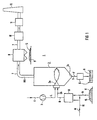
- the incinerator 1 shown in Figure 1 is part of a coal-fired power plant, not shown. It comprises a high-temperature combustion chamber designed as a melting chamber 2 with at least one burner 2a, and with a feed 2b, for example a conveyor belt for the coal K, and a fresh air line 4 guided over a compressor 3. It further comprises a discharge line 5 for liquid ash F with one on it connected wet purifier 6. It also comprises a flue gas line 7 and in the flue gas line 7 connected in series a dust filter system 8 with a fly ash collector 9, a flue gas desulfurization system 10 and a catalytic denitrification system 11. The flue gas line 7 opens into a chimney 12.
- the feed 2b is connected to a Coal mill 13 connected, which is connected to a feed shaft 14 of a coal store 15 and to a separate feed line 16 for adding material M containing titanium dioxide.
- the burnout acceleration of the coal K in the combustion chamber 2 is set via the amount of titanium dioxide-containing material M.
- the coal K is conveyed from the coal store 15 via the feed shaft 14 into the coal mill 13.
- the titanium dioxide-containing material M is either introduced via the feed line 16 and the feed shaft 14 or directly into the coal mill 13 and there, together with the coal K, is ground very finely.
- Fuel B prepared in this way reaches the combustion chamber 2 via the feed 2b and the burner 2a, where it is burned with compressed air L supplied via the fresh air line 4.
- the resulting flue gas RG flows via the flue gas line 7 into the dust filter system 8, where fly ash or fly dust S entrained by the flue gas is intercepted and discharged via the fly ash collector 9.
- the now practically dust-free flue gas RG arrives at the flue gas desulfurization system 10 and into the chimney 12 via the denoxification system 11, which is generally referred to as a DeNO x system.
- the liquid ash F collecting on the combustion chamber bottom 2c becomes via the discharge line 5 to the wet slag remover 6 and processed into granules G.
- the fly ash S collected at the collector 9 can be recycled as usual become.
- Up to 3% material containing titanium dioxide is advantageous M used with a titanium dioxide content of more than 50%.
- This melting chamber granulate G can be used as a building material as usual.
- the incinerator 1 with Melting chamber firing a fly ash return 20 on This opens directly into the combustion chamber 2 of the melting chamber furnace.
- the in the dust filter system 8 via the collector 9 restrained fly ash S is pneumatically using a additional compressor 21 blown into the combustion chamber 2.
- titanium dioxide-containing Dust-finely ground material M is added to the fly ash S. and gets into the combustion chamber 2 by adding Titanium dioxide-containing material M in the combustion chamber 2 of the coal-fired power plant with melting chamber firing in combination with a Fly ash return 20 becomes particularly effective burnout with a simultaneous acceleration of the throughput Coal K achieved in the power plant. This increases the performance of the Power plant.
- Additives contained in the fly ash S, which are contaminated with heavy metal, and titanium dioxide are insolubly incorporated into the resulting melting chamber granules G. In this way, used DeNO x catalysts with more than 50% TiO 2 can be disposed of without any problems.
- Example 1 Used DeNO x catalysts are used as the titanium dioxide-containing material M and mixed with coal K.
- a highly decarburized, high-ballast hard coal is used as coal K, which, according to its degree of decarburization and the proportion of volatile constituents, belongs to lean coal and lies on the border between lean coal and anthracite coal.
- the ashes of this coal show normal melting behavior.
- the catalyst used consists of approximately 75% TiO 2 and contains further catalytic components (approx. 11% SiO 2 , approx. 8% WO 3 and approx. 1.8% V 2 O 5 ).
- combustion tests are carried out in a combustion chamber 2.
- the combustion chamber 2 is designed as a laboratory combustion chamber, each with a liquid ash extractor and a dry ash extractor.
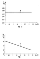
- the composition of the ash, the influence of the slagging behavior of the coal by adding used catalyst, the influence of the catalyst fraction M K on the slagging intensity of the heating surfaces behind the combustion chamber and the distribution of the catalyst material in the combustion residues are examined. An X-ray fluorescence analysis of these combustion residues is carried out.
- FIGS. 3 to 7 show the test results as an example for the combustion chamber with liquid ash extraction.
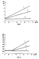
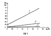
- Curves c, d and e of FIGS. 5 to 7 show the percentage of active catalyst substances TiO 2 (FIG. 5), V 2 O 5 (FIG. 6) and WO 3 (FIG. 7) in the slag F, in the fly ash S. or in the slag-like approaches.
- Another surprising result is that the catalyst is found primarily in the slag or liquid ash F (curve c, FIGS. 5 to 7) and partly in the fly ash S (curve d, FIGS. 5 to 7), but hardly in the slag-like approaches ( Curve e, Figures 5 to 7) takes place.
- M K (0 to 3%) in the fuel, only the proportions of TiO 2 (FIG. 5), V 2 O 5 (FIG. 6) and WO 3 (FIG. 7) in the slag F and in the fly ash S become clear to. In the slag-like approaches behind the combustion chamber, however, they remain practically unchanged.
- Example 2 Fly ash from an electrostatic precipitator of a coal-fired power plant with smelting chamber firing is mixed with calcium carbonate (CaCO 3 ) in a mass ratio of 100: 5. As a result, a melt can be obtained directly ("zero test”). The same mixture is mixed for comparison with dust-finely ground, used DeNO x catalyst in such a way that the catalyst content is 1%. The mixture is melted at 1550 ° C for 20 minutes and quenched in water ("comparative sample”). 5 g of the granules G obtained are eluted with 50 g of H 2 O for 24 hours and the eluate is examined for traces of vanadium V, tungsten W and arsenic as.
- CaCO 3 calcium carbonate
- the amount of active washed out from the comparative sample Catalyst substances (V, W) are below the detection limit ( ⁇ 0.1 mg / l).
- the arsenic content is in both samples in the same area.
Landscapes
- Chemical & Material Sciences (AREA)
- Engineering & Computer Science (AREA)
- Combustion & Propulsion (AREA)
- Oil, Petroleum & Natural Gas (AREA)
- Organic Chemistry (AREA)
- General Engineering & Computer Science (AREA)
- Mechanical Engineering (AREA)
- Physics & Mathematics (AREA)
- Thermal Sciences (AREA)
- Gasification And Melting Of Waste (AREA)
- Processing Of Solid Wastes (AREA)
- Solid Fuels And Fuel-Associated Substances (AREA)
- Exhaust Gas Treatment By Means Of Catalyst (AREA)
- Catalysts (AREA)
Applications Claiming Priority (3)
| Application Number | Priority Date | Filing Date | Title |
|---|---|---|---|
| DE19534558A DE19534558C1 (de) | 1995-09-18 | 1995-09-18 | Additiv zum Verbrennen von Kohle in einem Kohlekraftwerk mit Schmelzkammerfeuerung |
| DE19534558 | 1995-09-18 | ||
| PCT/DE1996/001721 WO1997011139A1 (de) | 1995-09-18 | 1996-09-12 | Verfahren zum betreiben einer verbrennungsanlage eines kohlekraftwerkes mit schmelzkammerfeuerung sowie danach arbeitende verbrennungsanlage |
Publications (2)
| Publication Number | Publication Date |
|---|---|
| EP0858495A1 EP0858495A1 (de) | 1998-08-19 |
| EP0858495B1 true EP0858495B1 (de) | 2003-07-02 |
Family
ID=7772466
Family Applications (1)
| Application Number | Title | Priority Date | Filing Date |
|---|---|---|---|
| EP96929184A Expired - Lifetime EP0858495B1 (de) | 1995-09-18 | 1996-09-12 | Verwendung eines verfahrens zum betreiben einer verbrennungsanlage eines kohlekraftwerkes zur beschleunigung des kohleausbrendes einer schmelzkammer |
Country Status (12)
| Country | Link |
|---|---|
| US (1) | US6067914A (enExample) |
| EP (1) | EP0858495B1 (enExample) |
| JP (1) | JP2989272B2 (enExample) |
| KR (1) | KR19990045747A (enExample) |
| CN (1) | CN1197477A (enExample) |
| AT (1) | ATE244292T1 (enExample) |
| CA (1) | CA2232476A1 (enExample) |
| DE (2) | DE19534558C1 (enExample) |
| ES (1) | ES2202461T3 (enExample) |
| RU (1) | RU2152428C1 (enExample) |
| TW (1) | TW301698B (enExample) |
| WO (1) | WO1997011139A1 (enExample) |
Families Citing this family (5)
| Publication number | Priority date | Publication date | Assignee | Title |
|---|---|---|---|---|
| JP4909296B2 (ja) * | 2008-02-12 | 2012-04-04 | 三菱重工業株式会社 | 重質燃料焚ボイラシステム及びその運転方法 |
| CN101524695B (zh) * | 2009-04-03 | 2011-06-08 | 沈阳航空工业学院 | 利用电厂飞灰生产漂珠的方法 |
| WO2015060795A1 (en) * | 2013-10-21 | 2015-04-30 | Dora Teknolojik Bilgisayar Ürünleri Endüstrisi Anonim Şirketi | Process for the minimization/elimination of so2 and co2 emission emerging from the combustion of coal |
| CN106635242A (zh) * | 2016-12-07 | 2017-05-10 | 江西稀有金属钨业控股集团有限公司 | 一种白钨精矿冶炼渣的利用方法、利用装置及用途 |
| CN114574262B (zh) * | 2022-03-04 | 2022-12-13 | 安徽工业大学 | 一种利用钛白废酸生产的燃煤催化剂及其制备方法 |
Family Cites Families (26)
| Publication number | Priority date | Publication date | Assignee | Title |
|---|---|---|---|---|
| US1947460A (en) * | 1927-01-31 | 1934-02-20 | Coutant Jay Gould | Pulverized fuel furnace and method of combustion |
| CH253222A (de) * | 1945-11-08 | 1948-02-29 | Rothenbach Walter Ing Dipl | Verfahren zur Herstellung eines Brennstoffes. |
| BE703706A (enExample) * | 1967-09-11 | 1968-02-01 | ||
| GB1402207A (en) * | 1972-03-03 | 1975-08-06 | Siemens Ag | Catalyst and its use in hydrocarbon cracking processes |
| US4057398A (en) * | 1976-02-24 | 1977-11-08 | Apollo Chemical Corporation | Process for reducing the fusion point of coal ash |
| US4388877A (en) * | 1981-07-07 | 1983-06-21 | Benmol Corporation | Method and composition for combustion of fossil fuels in fluidized bed |
| DE3128903C2 (de) * | 1981-07-22 | 1983-09-08 | L. & C. Steinmüller GmbH, 5270 Gummersbach | "Verfahren zum Eintragen von Additiv in einen Reaktionsgasstrom" |
| US4377118A (en) * | 1981-12-21 | 1983-03-22 | Nalco Chemical Company | Process for reducing slag build-up |
| US4577566A (en) * | 1982-04-01 | 1986-03-25 | Betz Laboratories, Inc. | Method of conditioning fireside fouling deposits using large particle size amorphous silica |
| DE3504122C2 (de) * | 1985-02-07 | 1994-02-03 | Kat Tec Ges Fuer Katalysatorte | Katalysator zur Umwandlung von Kohlenwasserstoffen, Stickoxiden und Brenngasen |
| JPS6348392A (ja) * | 1986-08-15 | 1988-03-01 | Toa Netsuken Kk | 石炭の排ガスダストのクリンカ−アツシユ抑制方法 |
| DE3635027A1 (de) * | 1986-10-15 | 1988-04-28 | Steinmueller Gmbh L & C | Direktentschwefelungsverfahren mit flugstaubrueckfuehrung |
| US4771712A (en) * | 1987-06-24 | 1988-09-20 | A. Ahlstrom Corporation | Combustion of fuel containing alkalines |
| DE3741604C1 (de) * | 1987-12-09 | 1989-02-23 | Metallgesellschaft Ag | Verfahren zur Abscheidung der Asche aus dem bei der Verbrennung von Kohle anfallenden Gas |
| EP0324454B2 (de) * | 1988-01-14 | 2000-08-30 | Siemens Aktiengesellschaft | Verfahren und Vorrichtung zur Reinigung von Rauchgasen |
| US4836117A (en) * | 1988-01-15 | 1989-06-06 | The Standard Oil Company | Oxidation catalyst and processes using same |
| US4843980A (en) * | 1988-04-26 | 1989-07-04 | Lucille Markham | Composition for use in reducing air contaminants from combustion effluents |
| US4979447A (en) * | 1988-06-08 | 1990-12-25 | Velino Ventures Inc. | Combustion of carbon containing materials in a furnace |
| JPH03244692A (ja) * | 1990-02-23 | 1991-10-31 | Taiho Ind Co Ltd | 燃料添加剤 |
| DE4013720C2 (de) * | 1990-04-28 | 1994-05-19 | Huels Chemische Werke Ag | Verfahren zur Verwertung von gebrauchten DeNOx-Katalysatoren |
| DE4021362A1 (de) * | 1990-07-05 | 1992-01-09 | Siemens Ag | Verfahren und vorrichtung zur entsorgung von mit schadstoffen beladenen rueckstaenden |
| DE4209166A1 (de) * | 1992-03-20 | 1993-09-23 | Siemens Ag | Verfahren und einrichtung zur katalytischen entfernung von schadstoffen aus rauchgas |
| RU2057165C1 (ru) * | 1992-06-26 | 1996-03-27 | Иванов Сергей Анатольевич | Присадка к бурым углям для факельного сжигания в топках энергетических котлов |
| US5309850A (en) * | 1992-11-18 | 1994-05-10 | The Babcock & Wilcox Company | Incineration of hazardous wastes using closed cycle combustion ash vitrification |
| DE4301814A1 (de) * | 1993-01-23 | 1994-07-28 | Steinmueller Gmbh L & C | Verfahren zum Verbrennen eines im wesentlichen aus Kunststoff bestehenden Abfalls, insbesondere PVC-Abfall |
| US5819672A (en) * | 1995-04-06 | 1998-10-13 | Addchem Systems | Treatment to enhance heat retention in coal and biomass burning furnaces |
-
1995
- 1995-09-18 DE DE19534558A patent/DE19534558C1/de not_active Expired - Fee Related
-
1996
- 1996-09-12 CA CA002232476A patent/CA2232476A1/en not_active Abandoned
- 1996-09-12 JP JP9512311A patent/JP2989272B2/ja not_active Expired - Fee Related
- 1996-09-12 WO PCT/DE1996/001721 patent/WO1997011139A1/de not_active Ceased
- 1996-09-12 ES ES96929184T patent/ES2202461T3/es not_active Expired - Lifetime
- 1996-09-12 AT AT96929184T patent/ATE244292T1/de not_active IP Right Cessation
- 1996-09-12 CN CN96197176A patent/CN1197477A/zh active Pending
- 1996-09-12 DE DE59610578T patent/DE59610578D1/de not_active Expired - Lifetime
- 1996-09-12 KR KR1019980701990A patent/KR19990045747A/ko not_active Ceased
- 1996-09-12 RU RU98107258/12A patent/RU2152428C1/ru not_active IP Right Cessation
- 1996-09-12 EP EP96929184A patent/EP0858495B1/de not_active Expired - Lifetime
- 1996-09-18 TW TW085111387A patent/TW301698B/zh active
-
1998
- 1998-03-18 US US09/040,970 patent/US6067914A/en not_active Expired - Lifetime
Also Published As
| Publication number | Publication date |
|---|---|
| EP0858495A1 (de) | 1998-08-19 |
| WO1997011139A1 (de) | 1997-03-27 |
| KR19990045747A (ko) | 1999-06-25 |
| TW301698B (enExample) | 1997-04-01 |
| CN1197477A (zh) | 1998-10-28 |
| ATE244292T1 (de) | 2003-07-15 |
| CA2232476A1 (en) | 1997-03-27 |
| DE59610578D1 (de) | 2003-08-07 |
| JP2989272B2 (ja) | 1999-12-13 |
| DE19534558C1 (de) | 1996-11-07 |
| ES2202461T3 (es) | 2004-04-01 |
| US6067914A (en) | 2000-05-30 |
| JPH11502897A (ja) | 1999-03-09 |
| RU2152428C1 (ru) | 2000-07-10 |
Similar Documents
| Publication | Publication Date | Title |
|---|---|---|
| EP0515792B1 (de) | Verfahren zum Behandeln von Rückständen einer Abfallverbrennungsanlage und Abfallverbrennungsanlage zur Durchführung des Verfahrens | |
| EP0118931B1 (de) | Verfahren zur Nachverbrennung und Reinigung von Prozessabgasen | |
| EP0437679B1 (de) | Verfahren zum Behandeln von Rückständen einer Abfallverbrennungsanlage und Abfallverbrennungsanlage zur Durchfürhung des Verfahrens | |
| DE3915992A1 (de) | Verfahren zur reduktion von stickstoffoxiden | |
| CH622082A5 (enExample) | ||
| EP0338103B1 (de) | Verfahren zum Vermindern der Schadstoffemissionen beim Betrieb von Kohleverbrennungseinrichtungen | |
| WO1999005329A1 (de) | Verfahren zum betrieb einer sinteranlage sowie sinteranlage | |
| EP0862019B1 (de) | Verfahren und Vorrichtung zur thermischen Behandlung von Flugstäuben aus Rostverbrennungsanlagen | |
| DD286295A5 (de) | Verfahren und vorrichtung zur aufarbeitung kontaminierter boeden | |
| DE3536635C2 (enExample) | ||
| DE3604318C2 (de) | Verfahren zur Verbrennung von Kuhmist | |
| EP0340644B1 (de) | Verfahren zur Beseitigung und zum Recycling von Abfallstoffen | |
| DE3247228C2 (de) | Verfahren zur Rückgewinnung von unverbrannter Kohle aus Kohlenasche | |
| EP0324454B2 (de) | Verfahren und Vorrichtung zur Reinigung von Rauchgasen | |
| DE4013720C2 (de) | Verfahren zur Verwertung von gebrauchten DeNOx-Katalysatoren | |
| EP0368962B1 (de) | Verfahren und vorrichtung zum reinigen von schlacke aus abfallverbrennungsöfen | |
| EP0858495B1 (de) | Verwendung eines verfahrens zum betreiben einer verbrennungsanlage eines kohlekraftwerkes zur beschleunigung des kohleausbrendes einer schmelzkammer | |
| DE3520447A1 (de) | Verfahren und anlage zur thermischen behandlung von feinkoernigem gut wie zementrohmehl, unter verwendung von brennstoffhaltigen abfaellen und/oder minderwertigen brennstoffen | |
| EP1359374B1 (de) | Verfahren zur Behandlung von Verbrennungsrückständen einer Verbrennungsanlage | |
| DE3733831C2 (enExample) | ||
| DE3324411C2 (enExample) | ||
| DE10341610B4 (de) | Verfahren zur Verbrennung von festen Abfällen | |
| DE4209166A1 (de) | Verfahren und einrichtung zur katalytischen entfernung von schadstoffen aus rauchgas | |
| DE3841221A1 (de) | Verfahren zum reinigen der rauchgase von verbrennungsanlagen | |
| EP1111305A1 (de) | Verfahren zur thermischen Behandlung von Rostasche aus Müllverbrennungsanlagen |
Legal Events
| Date | Code | Title | Description |
|---|---|---|---|
| PUAI | Public reference made under article 153(3) epc to a published international application that has entered the european phase |
Free format text: ORIGINAL CODE: 0009012 |
|
| 17P | Request for examination filed |
Effective date: 19980304 |
|
| AK | Designated contracting states |
Kind code of ref document: A1 Designated state(s): AT CH DE DK ES FI FR GB IT LI NL SE |
|
| 17Q | First examination report despatched |
Effective date: 19990121 |
|
| RAP1 | Party data changed (applicant data changed or rights of an application transferred) |
Owner name: STEAG ENCOTEC GMBH Owner name: SIEMENS AKTIENGESELLSCHAFT |
|
| GRAH | Despatch of communication of intention to grant a patent |
Free format text: ORIGINAL CODE: EPIDOS IGRA |
|
| RTI1 | Title (correction) |
Free format text: USE OF A PROCESS OPERATING A COMBUSTION PLANT OF A COAL-FIRED POWER STATION FOR THE ACCELERATED COAL COMBUSTION IN A SMELT CHAMBER |
|
| GRAH | Despatch of communication of intention to grant a patent |
Free format text: ORIGINAL CODE: EPIDOS IGRA |
|
| GRAA | (expected) grant |
Free format text: ORIGINAL CODE: 0009210 |
|
| AK | Designated contracting states |
Designated state(s): AT CH DE DK ES FI FR GB IT LI NL SE |
|
| PG25 | Lapsed in a contracting state [announced via postgrant information from national office to epo] |
Ref country code: FR Free format text: LAPSE BECAUSE OF FAILURE TO SUBMIT A TRANSLATION OF THE DESCRIPTION OR TO PAY THE FEE WITHIN THE PRESCRIBED TIME-LIMIT Effective date: 20030702 Ref country code: FI Free format text: LAPSE BECAUSE OF FAILURE TO SUBMIT A TRANSLATION OF THE DESCRIPTION OR TO PAY THE FEE WITHIN THE PRESCRIBED TIME-LIMIT Effective date: 20030702 |
|
| REG | Reference to a national code |
Ref country code: GB Ref legal event code: FG4D Free format text: NOT ENGLISH |
|
| REG | Reference to a national code |
Ref country code: CH Ref legal event code: EP |
|
| REF | Corresponds to: |
Ref document number: 59610578 Country of ref document: DE Date of ref document: 20030807 Kind code of ref document: P |
|
| PG25 | Lapsed in a contracting state [announced via postgrant information from national office to epo] |
Ref country code: SE Free format text: LAPSE BECAUSE OF FAILURE TO SUBMIT A TRANSLATION OF THE DESCRIPTION OR TO PAY THE FEE WITHIN THE PRESCRIBED TIME-LIMIT Effective date: 20031002 Ref country code: DK Free format text: LAPSE BECAUSE OF FAILURE TO SUBMIT A TRANSLATION OF THE DESCRIPTION OR TO PAY THE FEE WITHIN THE PRESCRIBED TIME-LIMIT Effective date: 20031002 |
|
| REG | Reference to a national code |
Ref country code: CH Ref legal event code: NV Representative=s name: DR. LUSUARDI AG |
|
| GBT | Gb: translation of ep patent filed (gb section 77(6)(a)/1977) |
Effective date: 20031022 |
|
| REG | Reference to a national code |
Ref country code: ES Ref legal event code: FG2A Ref document number: 2202461 Country of ref document: ES Kind code of ref document: T3 |
|
| PLBE | No opposition filed within time limit |
Free format text: ORIGINAL CODE: 0009261 |
|
| STAA | Information on the status of an ep patent application or granted ep patent |
Free format text: STATUS: NO OPPOSITION FILED WITHIN TIME LIMIT |
|
| 26N | No opposition filed |
Effective date: 20040405 |
|
| EN | Fr: translation not filed | ||
| REG | Reference to a national code |
Ref country code: CH Ref legal event code: PFA Owner name: SIEMENS AKTIENGESELLSCHAFT Free format text: SIEMENS AKTIENGESELLSCHAFT#WITTELSBACHERPLATZ 2#80333 MUENCHEN (DE) $ STEAG ENCOTEC GMBH#RUETTENSCHEIDER STRASSE 1-3#45128 ESSEN (DE) -TRANSFER TO- SIEMENS AKTIENGESELLSCHAFT#WITTELSBACHERPLATZ 2#80333 MUENCHEN (DE) $ STEAG ENCOTEC GMBH#RUETTENSCHEIDER STRASSE 1-3#45128 ESSEN (DE) |
|
| PGFP | Annual fee paid to national office [announced via postgrant information from national office to epo] |
Ref country code: CH Payment date: 20080923 Year of fee payment: 13 |
|
| PGFP | Annual fee paid to national office [announced via postgrant information from national office to epo] |
Ref country code: NL Payment date: 20080922 Year of fee payment: 13 Ref country code: IT Payment date: 20080925 Year of fee payment: 13 Ref country code: AT Payment date: 20080919 Year of fee payment: 13 |
|
| REG | Reference to a national code |
Ref country code: CH Ref legal event code: PUEA Owner name: STEAG ENCOTEC GMBH Free format text: SIEMENS AKTIENGESELLSCHAFT#WITTELSBACHERPLATZ 2#80333 MUENCHEN (DE) $ STEAG ENCOTEC GMBH#RUETTENSCHEIDER STRASSE 1-3#45128 ESSEN (DE) -TRANSFER TO- STEAG ENCOTEC GMBH#RUETTENSCHEIDER STRASSE 1-3#45128 ESSEN (DE) $ ARGILLON GMBH#BAHNHOFSTRASSE 43#96257 REDWITZ (DE) Ref country code: CH Ref legal event code: PFA Owner name: ARGILLON GMBH Free format text: STEAG ENCOTEC GMBH#RUETTENSCHEIDER STRASSE 1-3#45128 ESSEN (DE) $ ARGILLON GMBH#BAHNHOFSTRASSE 43#96257 REDWITZ (DE) -TRANSFER TO- ARGILLON GMBH#BAHNHOFSTRASSE 43#96257 REDWITZ (DE) $ EVONIK ENERGY SERVICES GMBH#RUETTENSCHEIDER STRASSE 1-3#45128 ESSEN (DE) |
|
| REG | Reference to a national code |
Ref country code: GB Ref legal event code: 732E Free format text: REGISTERED BETWEEN 20090528 AND 20090603 |
|
| REG | Reference to a national code |
Ref country code: ES Ref legal event code: PC2A |
|
| NLS | Nl: assignments of ep-patents |
Owner name: STEAG ENCOTEC GMBH Effective date: 20100112 Owner name: ARGILLON GMBH Effective date: 20100112 |
|
| REG | Reference to a national code |
Ref country code: NL Ref legal event code: V1 Effective date: 20100401 |
|
| REG | Reference to a national code |
Ref country code: CH Ref legal event code: PL |
|
| PG25 | Lapsed in a contracting state [announced via postgrant information from national office to epo] |
Ref country code: AT Free format text: LAPSE BECAUSE OF NON-PAYMENT OF DUE FEES Effective date: 20090912 |
|
| PG25 | Lapsed in a contracting state [announced via postgrant information from national office to epo] |
Ref country code: NL Free format text: LAPSE BECAUSE OF NON-PAYMENT OF DUE FEES Effective date: 20100401 |
|
| PG25 | Lapsed in a contracting state [announced via postgrant information from national office to epo] |
Ref country code: LI Free format text: LAPSE BECAUSE OF NON-PAYMENT OF DUE FEES Effective date: 20090930 Ref country code: CH Free format text: LAPSE BECAUSE OF NON-PAYMENT OF DUE FEES Effective date: 20090930 |
|
| PG25 | Lapsed in a contracting state [announced via postgrant information from national office to epo] |
Ref country code: IT Free format text: LAPSE BECAUSE OF NON-PAYMENT OF DUE FEES Effective date: 20090912 |
|
| PGFP | Annual fee paid to national office [announced via postgrant information from national office to epo] |
Ref country code: DE Payment date: 20110923 Year of fee payment: 16 Ref country code: ES Payment date: 20110926 Year of fee payment: 16 Ref country code: GB Payment date: 20110920 Year of fee payment: 16 |
|
| REG | Reference to a national code |
Ref country code: DE Ref legal event code: R082 Ref document number: 59610578 Country of ref document: DE Representative=s name: FDST PATENTANWAELTE FREIER DOERR STAMMLER TSCH, DE Effective date: 20111020 Ref country code: DE Ref legal event code: R081 Ref document number: 59610578 Country of ref document: DE Owner name: JOHNSON MATTHEY CATALYSTS (GERMANY) GMBH, DE Free format text: FORMER OWNERS: ARGILLON GMBH, 96257 REDWITZ, DE; EVONIK ENERGY SERVICES GMBH, 45128 ESSEN, DE Effective date: 20111020 Ref country code: DE Ref legal event code: R081 Ref document number: 59610578 Country of ref document: DE Owner name: STEAG ENERGY SERVICES GMBH, DE Free format text: FORMER OWNERS: ARGILLON GMBH, 96257 REDWITZ, DE; EVONIK ENERGY SERVICES GMBH, 45128 ESSEN, DE Effective date: 20111020 Ref country code: DE Ref legal event code: R081 Ref document number: 59610578 Country of ref document: DE Owner name: STEAG ENERGY SERVICES GMBH, DE Free format text: FORMER OWNER: ARGILLON GMBH, EVONIK ENERGY SERVICES GMBH, , DE Effective date: 20111020 Ref country code: DE Ref legal event code: R081 Ref document number: 59610578 Country of ref document: DE Owner name: JOHNSON MATTHEY CATALYSTS (GERMANY) GMBH, DE Free format text: FORMER OWNER: ARGILLON GMBH, EVONIK ENERGY SERVICES GMBH, , DE Effective date: 20111020 |
|
| REG | Reference to a national code |
Ref country code: ES Ref legal event code: PC2A Owner name: JOHNSON MATTHEY CATALYSTS(GERMANY)GMBH Effective date: 20120409 |
|
| GBPC | Gb: european patent ceased through non-payment of renewal fee |
Effective date: 20120912 |
|
| PG25 | Lapsed in a contracting state [announced via postgrant information from national office to epo] |
Ref country code: DE Free format text: LAPSE BECAUSE OF NON-PAYMENT OF DUE FEES Effective date: 20130403 Ref country code: GB Free format text: LAPSE BECAUSE OF NON-PAYMENT OF DUE FEES Effective date: 20120912 |
|
| REG | Reference to a national code |
Ref country code: DE Ref legal event code: R119 Ref document number: 59610578 Country of ref document: DE Effective date: 20130403 |
|
| REG | Reference to a national code |
Ref country code: ES Ref legal event code: FD2A Effective date: 20131021 |
|
| PG25 | Lapsed in a contracting state [announced via postgrant information from national office to epo] |
Ref country code: ES Free format text: LAPSE BECAUSE OF NON-PAYMENT OF DUE FEES Effective date: 20120913 |