EP0855243A2 - Dispositif de retenue, en particulier pour pièces à usiner - Google Patents
Dispositif de retenue, en particulier pour pièces à usiner Download PDFInfo
- Publication number
- EP0855243A2 EP0855243A2 EP98101204A EP98101204A EP0855243A2 EP 0855243 A2 EP0855243 A2 EP 0855243A2 EP 98101204 A EP98101204 A EP 98101204A EP 98101204 A EP98101204 A EP 98101204A EP 0855243 A2 EP0855243 A2 EP 0855243A2
- Authority
- EP
- European Patent Office
- Prior art keywords
- pressure
- piston
- housing
- chamber
- axially
- Prior art date
- Legal status (The legal status is an assumption and is not a legal conclusion. Google has not performed a legal analysis and makes no representation as to the accuracy of the status listed.)
- Withdrawn
Links
Images


Classifications
-
- B—PERFORMING OPERATIONS; TRANSPORTING
- B23—MACHINE TOOLS; METAL-WORKING NOT OTHERWISE PROVIDED FOR
- B23Q—DETAILS, COMPONENTS, OR ACCESSORIES FOR MACHINE TOOLS, e.g. ARRANGEMENTS FOR COPYING OR CONTROLLING; MACHINE TOOLS IN GENERAL CHARACTERISED BY THE CONSTRUCTION OF PARTICULAR DETAILS OR COMPONENTS; COMBINATIONS OR ASSOCIATIONS OF METAL-WORKING MACHINES, NOT DIRECTED TO A PARTICULAR RESULT
- B23Q16/00—Equipment for precise positioning of tool or work into particular locations not otherwise provided for
- B23Q16/02—Indexing equipment
- B23Q16/08—Indexing equipment having means for clamping the relatively movable parts together in the indexed position
-
- B—PERFORMING OPERATIONS; TRANSPORTING
- B23—MACHINE TOOLS; METAL-WORKING NOT OTHERWISE PROVIDED FOR
- B23Q—DETAILS, COMPONENTS, OR ACCESSORIES FOR MACHINE TOOLS, e.g. ARRANGEMENTS FOR COPYING OR CONTROLLING; MACHINE TOOLS IN GENERAL CHARACTERISED BY THE CONSTRUCTION OF PARTICULAR DETAILS OR COMPONENTS; COMBINATIONS OR ASSOCIATIONS OF METAL-WORKING MACHINES, NOT DIRECTED TO A PARTICULAR RESULT
- B23Q1/00—Members which are comprised in the general build-up of a form of machine, particularly relatively large fixed members
- B23Q1/0063—Connecting non-slidable parts of machine tools to each other
- B23Q1/0081—Connecting non-slidable parts of machine tools to each other using an expanding clamping member insertable in a receiving hole
-
- B—PERFORMING OPERATIONS; TRANSPORTING
- B23—MACHINE TOOLS; METAL-WORKING NOT OTHERWISE PROVIDED FOR
- B23Q—DETAILS, COMPONENTS, OR ACCESSORIES FOR MACHINE TOOLS, e.g. ARRANGEMENTS FOR COPYING OR CONTROLLING; MACHINE TOOLS IN GENERAL CHARACTERISED BY THE CONSTRUCTION OF PARTICULAR DETAILS OR COMPONENTS; COMBINATIONS OR ASSOCIATIONS OF METAL-WORKING MACHINES, NOT DIRECTED TO A PARTICULAR RESULT
- B23Q16/00—Equipment for precise positioning of tool or work into particular locations not otherwise provided for
- B23Q16/02—Indexing equipment
- B23Q16/021—Indexing equipment in which only the positioning elements are of importance
-
- B—PERFORMING OPERATIONS; TRANSPORTING
- B23—MACHINE TOOLS; METAL-WORKING NOT OTHERWISE PROVIDED FOR
- B23Q—DETAILS, COMPONENTS, OR ACCESSORIES FOR MACHINE TOOLS, e.g. ARRANGEMENTS FOR COPYING OR CONTROLLING; MACHINE TOOLS IN GENERAL CHARACTERISED BY THE CONSTRUCTION OF PARTICULAR DETAILS OR COMPONENTS; COMBINATIONS OR ASSOCIATIONS OF METAL-WORKING MACHINES, NOT DIRECTED TO A PARTICULAR RESULT
- B23Q16/00—Equipment for precise positioning of tool or work into particular locations not otherwise provided for
- B23Q16/02—Indexing equipment
- B23Q16/04—Indexing equipment having intermediate members, e.g. pawls, for locking the relatively movable parts in the indexed position
-
- Y—GENERAL TAGGING OF NEW TECHNOLOGICAL DEVELOPMENTS; GENERAL TAGGING OF CROSS-SECTIONAL TECHNOLOGIES SPANNING OVER SEVERAL SECTIONS OF THE IPC; TECHNICAL SUBJECTS COVERED BY FORMER USPC CROSS-REFERENCE ART COLLECTIONS [XRACs] AND DIGESTS
- Y10—TECHNICAL SUBJECTS COVERED BY FORMER USPC
- Y10T—TECHNICAL SUBJECTS COVERED BY FORMER US CLASSIFICATION
- Y10T279/00—Chucks or sockets
- Y10T279/10—Expanding
- Y10T279/1021—Fluid-pressure actuator
- Y10T279/1033—Expanding jaws via mechanical connection
-
- Y—GENERAL TAGGING OF NEW TECHNOLOGICAL DEVELOPMENTS; GENERAL TAGGING OF CROSS-SECTIONAL TECHNOLOGIES SPANNING OVER SEVERAL SECTIONS OF THE IPC; TECHNICAL SUBJECTS COVERED BY FORMER USPC CROSS-REFERENCE ART COLLECTIONS [XRACs] AND DIGESTS
- Y10—TECHNICAL SUBJECTS COVERED BY FORMER USPC
- Y10T—TECHNICAL SUBJECTS COVERED BY FORMER US CLASSIFICATION
- Y10T279/00—Chucks or sockets
- Y10T279/10—Expanding
- Y10T279/1037—Axially moving actuator
- Y10T279/1041—Wedge
- Y10T279/1045—Internal cone
-
- Y—GENERAL TAGGING OF NEW TECHNOLOGICAL DEVELOPMENTS; GENERAL TAGGING OF CROSS-SECTIONAL TECHNOLOGIES SPANNING OVER SEVERAL SECTIONS OF THE IPC; TECHNICAL SUBJECTS COVERED BY FORMER USPC CROSS-REFERENCE ART COLLECTIONS [XRACs] AND DIGESTS
- Y10—TECHNICAL SUBJECTS COVERED BY FORMER USPC
- Y10T—TECHNICAL SUBJECTS COVERED BY FORMER US CLASSIFICATION
- Y10T279/00—Chucks or sockets
- Y10T279/10—Expanding
- Y10T279/1083—Jaw structure
- Y10T279/1091—Ball or roller
-
- Y—GENERAL TAGGING OF NEW TECHNOLOGICAL DEVELOPMENTS; GENERAL TAGGING OF CROSS-SECTIONAL TECHNOLOGIES SPANNING OVER SEVERAL SECTIONS OF THE IPC; TECHNICAL SUBJECTS COVERED BY FORMER USPC CROSS-REFERENCE ART COLLECTIONS [XRACs] AND DIGESTS
- Y10—TECHNICAL SUBJECTS COVERED BY FORMER USPC
- Y10T—TECHNICAL SUBJECTS COVERED BY FORMER US CLASSIFICATION
- Y10T279/00—Chucks or sockets
- Y10T279/12—Chucks or sockets with fluid-pressure actuator
Definitions
- the invention relates to a holding device a housing arranged clamping elements through an axial movement of a pressure member is radially movable are, wherein the pressure member extending into the housing of a first and a second pressure medium is axially acted upon and the second pressure medium the pressure member opposite to the first pressure medium acts.
- EP-A-0255 042 there is a holding device in the form of on a machine tool, for example an electric discharge machine attachable chuck described with which a workpiece or tool can be held. It intervenes with the workpiece detachable draw bolt in an opening of the chuck a, in which the draw bolt by means of a ball ratchet held under the action of compression springs and by means of compressed air which counteracts the compression springs can be solved.
- the invention is based on the object at the outset to simplify mentioned holding device significantly.
- the invention provides that in the housing two by a section axially movable and am Housing anchored membrane separated axially one behind the other arranged chambers are formed, the Pressure member is connected to the membrane and at least one of the chambers can be connected to a medium pressure source is. So that the holding device can be essential overall run flatter, including manufacturing costs are very low. Furthermore, the response time of the pressure member on the first or second Pressure medium extremely short, so that the clamping and loosening a workpiece on or from the holding device according to the invention very quickly and vigorously done.
- the membrane advantageously consists of a disc or a ring made of flexible plastic, for example Rubber. It is also recommended that the pressure piece in the housing, expediently inserted into one in the housing Pipe piece to guide axially.
- the pressure piece can consist of a cylindrical piston, on the free End cone surfaces are formed, against which the Apply clamping elements.
- Advantageously is on the foot of the piston an almost completely radially filling the chambers Plate attached, the clamped on the housing Membrane is attached to the edge of the plate. Between a chamber floor and the underside of the plate can then a plate spring can be clamped as pressure center 1.
- the invention can be particularly favorable in this regard evolve that using an auxiliary piston or another stamp the release pressure is essential can be increased.
- the increased release pressure ensures for a quick and easy release of the Workpiece without jamming or the like occur.
- the invention enables a stroke of the pressure member between holding and releasing only about 1-3 mm.
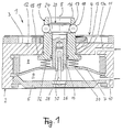
- the feed designated as a whole with 1 according to FIG. 1 has a housing 2, for example made of tool steel, whose central axis is designated 5.
- a housing 2 for example made of tool steel, whose central axis is designated 5.
- On the top 3 of the cylindrical or rectangular housing block 2 are reference elements designated as a whole by 4 in the form of grooves or not shown pins trained, which are designed with counter-reference elements on the bottom of a not shown Pallet for their exact, repeatable positioning relative to the housing block 2 in a spatial orthogonal system interact, its X-Y plane for example parallel to the top 3 and its Z axis in the center line 5.
- Such reference elements and counter-reference elements are per se, for example known from document EP-A-0255042, so that here are not shown and described.
- the Housing block 2 On the side opposite the top 3 is the Housing block 2 closed by a plate 6. Of the hollow interior of the housing block 2 is by a axial, i.e. 5 movable in the direction of the center line and anchored in the side walls of the housing block 2 Membrane 7 in a front chamber 8 and a rear chamber 9 divided.
- the rear chamber 9 has an in the outside of the housing block 2 leading through hole 10, via which the rear chamber 9 to a not shown compressed air source via suitable control means can be connected.
- a thick-walled pipe section 19 used, which with an inner, radially projecting Ring collar 15 the inner surface of the face plate 12 caught up.
- the pipe section 19 is from the top 3 and via the reference elements 4 around a section 16 outwards, in which several in the circumferential direction equally spaced radial bores are introduced.
- One of these radial bores is designated 17.
- In each of these radial bores 17 is a ball, for example the ball 18 in the radial bore 17, radially movable captured so that none of the balls 18 their associated Radial bore can leave radially outwards.
- a piston 20 is located in the central channel of the pipe section 19 guided axially displaceably and by means of a Annular groove of the tube piece 19 inserted ring seal 14 sealed against the front chamber 8.
- the widespread The head of the piston 20 is in a radial extension of the central channel and is on its periphery formed to an outwardly widening cone 24.
- Each of the balls 18 lies, as shown in Fig. 1 is on the cone 24 such that at a Inward movement of the piston 20 in the chamber 8 the balls 18 are pushed radially outwards and at one Outward movement of the piston 20, the balls 18 in their Radial bores 17 can be moved radially inwards.
- the tube piece 19 thus forms with radial bores 17, the balls 18 and the piston 20 a ball ratchet.
- the inner end of the piston shaft 26 is with the top connected to the membrane 7, one in the piston skirt 26 inserted sleeve 28 through a central Opening in the membrane 7 stretches.
- the sleeve 28 includes one standing upright on the plate 6 in the middle Finger 30 so that the piston 20 at its Axial movements in the direction of the central axis 5 not only through the central channel of the adapter 14, but also is guided by the finger 30.
- compression springs 32, 34 are already equally spaced in the circumferential direction mentioned compression springs 32, 34 arranged, of which each is supported on the top of the membrane 7 and bears against the underside of the collar 13.
- the holding force of the chuck 1 is increased in that the front chamber 8 is pressurized with compressed air, the the holding force of the piston 20 over that of the Compression springs 32, 34 developed holding force increased.
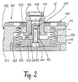
- the second embodiment of the invention according to Fig. 2 differs from that described above Embodiment essentially in that the Membrane 7 through one over several compression springs 132, 134 on the end plate 112 supporting thrust piston 107 is replaced, at the central section of which Piston shaft 126 anchored by means of a bolt 127 is.
- the thrust piston 107 is along the inner walls of the Shell 121 of the housing block 102 of the whole with 100 designated feed axially displaceable and borders thus the front chamber 108 against the rear chamber 109 from.
- the rear chamber 109 with sufficient Air pressure is applied so that the thrust piston 107 with Pistons 120 are moved outward and balls 118 enable a radially inward evasive movement.
- the invention increases the holding force that the effective area of the thrust piston 207 around the effective area of an auxiliary piston 240 is increased, which is arranged coaxially behind the push piston 207 and with this via an intermediate plate 242 penetrating Pin 224 is connected.
- Compression springs 232, 234 are supported on the one hand on the end plate 212 on the other hand on the push piston 207.
- the rear chamber 209 and the compressed air duct can via a compressed air connection 210 and the pre-earth chamber 208 can each via a compressed air connection 211 Control devices not shown with a compressed air source get connected.
- the increase in the holding force is achieved in that when the front chamber 208 is pressurized at the same time the intermediate chamber 248 at the same pressure is acted on with the result that the auxiliary piston 240 the thrust piston 207, with which it over the pin 224 is connected, pulling further inward, this Traction from the two pistons via a bolt 260 directly is transferred to the piston 220.
- the release force is initially set by the in the rear chamber 209 acting on the push piston 207 Air pressure on, which only at the end of channel 250 by the auxiliary piston carried by the push piston 207 240 by the pressure prevailing in the auxiliary chamber 254 is increased.
- the housing block 302 is opposed to the invention its end plate 312 around an extension 346 in axial Extended direction, in which a cross to the center line 305 of the housing block 302 transversely displaceable stamp 340 is arranged.
- the stamp 340 is with his spread head 341 slidable in a recess 344, the longitudinal direction of which is transverse to the center line 305 lies.
- the one in front of the face of head 341 Part of the recess 344 is via a medium channel 310 connected to the exterior of the housing block 302.
- the slender end 348 opposite the head 341 of the stamp 340 is in a continuation of the recess 344 Blind bore 350 can be moved transversely to the center line 305, and relatively weak against the effect a compression spring 352 located at the dead end of the bore 350 supports.
- a medium side channel 354 branches from the medium channel 310 from, which is parallel to the longitudinal extent of the recess 344 extends and behind the end 348 of the stamp 340 opens into the bore 350, the punch 340 then in a front starting position shown in FIG. 4 located.
- the bore 350 is over another Medium channel 356 connected to the rear turret 309 and branches from hole 350 near theirs blindly.
- the interior of the housing block 302 is through a push piston 307 again in a front chamber 308 which over a compressed air connection 311 with a compressed air source is connectable, and divides the mentioned rear chamber 309, the thrust piston 307 along the inner wall of the casing of the housing block 302 against the action of several, compression springs supported in the end plate 312 332, 334 is axially displaceable.
- the thrust piston 307 is about a bolt 360 with the symmetrical to Center line 305 arranged and displaceable in its direction Piston 320 firmly connected.
- the closing pressure for the ball lock 317, 318 is on the one hand by the compression springs 332, 334 and on the other hand Compressed air supplied through the front chamber 308 is generated.
- the thrust piston picks up 307 its bottom dead center position shown in FIG. 4 one in which the head of the pin 360 on the Interior of the housing block 302 (except for the medium channel 356) final plate 342 rests.
- the spring 352 only serves to remove the stamp 340 a position closing channel 354 after reduction of the pressure supplied with the medium channel Compressed air back to the starting position shown in Fig. 4 push back.
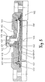
- FIG. 5 shows a further embodiment of the invention, in which the housing 402 essentially one encloses cylindrical cavity 408, 409.
- the Cavity 408, 409 has a central axial opening, in which a cylindrical pipe section 419 is firmly inserted is.
- the pipe section 419 rises above the surface 403 of the housing 402 and has a circumference at the free end equally distributed radial bores 417, a ball 418 in each of the radial bores a ball ratchet is captured radially movable.
- a piston is in the central bore of the pipe section 419 420 axially displaceable and sealed, the one at the free end with stepped radially inwards Wedge surfaces 421, 422 is provided.
- the balls 418 of the Ball locks lie radially on the wedge surfaces 421, 422.
- 409 of the cylindrical piston 420 is disc-shaped Plate 440 attached which defines cavity 408, 409 radially largely filled.
- a ring-shaped rubber membrane 407 is along its outer edge 437 on housing 402 clamped and its inner edge 427 is on the edge the plate 440 attached. Through the membrane 407 the cavity into a front chamber 408 and a rear one Chamber 409 divided.
- An axially expanding spring ring 450 is supported on its outer edge on the floor 424 of the rear chamber 409 and applies its inner edge the bottom of plate 440.
- a first in the front chamber is not shown 408 opening pressure medium channel, through which the front Chamber 408 from an external source of pressure medium Pressure can be applied. Furthermore, it is not shown another communicating with the rear chamber 409 Pressure medium channel that via an outer Rear chamber pressure medium source 409 medium pressure can supply.
- the center line 405 of the piston 420 is also the Direction of the Z axis.
- FIG. 5 shows the piston 420 with plate 440 and membrane edge 427 in one by the effect the spring ring 450 raised position in which the balls 418 by the piston 420 radially outward in one holding a workpiece, for example a pallet Position, are crowded.
- the right half of FIG. 5 shows a lowered position of the piston 420, the by pressurizing the front chamber 408 against the effect of the spring ring 450 is achieved so that the balls 418 of the ball ratchet radially inward can move and detach the workpiece from the Allow holding device.
- it is Bottom dead center of the piston stroke is reached when the Plate 440 sits on chamber bottom 424.
- the upper The dead center of the piston stroke is through the workpiece defines that only a limited radial Outward movement of balls 418 allowed.
Landscapes
- Engineering & Computer Science (AREA)
- Mechanical Engineering (AREA)
- Jigs For Machine Tools (AREA)
- Actuator (AREA)
- Clamps And Clips (AREA)
Applications Claiming Priority (2)
| Application Number | Priority Date | Filing Date | Title |
|---|---|---|---|
| DE19702227 | 1997-01-23 | ||
| DE19702227A DE19702227A1 (de) | 1997-01-23 | 1997-01-23 | Haltevorrichtung insbesondere für ein Werkstück |
Publications (2)
| Publication Number | Publication Date |
|---|---|
| EP0855243A2 true EP0855243A2 (fr) | 1998-07-29 |
| EP0855243A3 EP0855243A3 (fr) | 2001-08-01 |
Family
ID=7818085
Family Applications (1)
| Application Number | Title | Priority Date | Filing Date |
|---|---|---|---|
| EP98101204A Withdrawn EP0855243A3 (fr) | 1997-01-23 | 1998-01-23 | Dispositif de retenue, en particulier pour pièces à usiner |
Country Status (7)
| Country | Link |
|---|---|
| US (1) | US5997011A (fr) |
| EP (1) | EP0855243A3 (fr) |
| JP (1) | JP2000507167A (fr) |
| CN (1) | CN1216012A (fr) |
| DE (1) | DE19702227A1 (fr) |
| TW (1) | TW429199B (fr) |
| WO (1) | WO1998032565A2 (fr) |
Cited By (2)
| Publication number | Priority date | Publication date | Assignee | Title |
|---|---|---|---|---|
| EP2650079A1 (fr) * | 2012-04-13 | 2013-10-16 | ASA Electronics Industry Co., Ltd. | Appareil de serrage de palette pour machines-outils |
| CN116038373A (zh) * | 2022-12-21 | 2023-05-02 | 山东普集圣源锻造有限公司 | 一种减速机外壳加工工装及其加工工艺 |
Families Citing this family (27)
| Publication number | Priority date | Publication date | Assignee | Title |
|---|---|---|---|---|
| DE59907157D1 (de) * | 1998-07-29 | 2003-11-06 | Spannsysteme Gmbh Goetzi Stark | Deckelloser Schnellspannzylinder |
| GB0011714D0 (en) * | 2000-05-15 | 2000-07-05 | Westwind Air Bearings Ltd | Data storage disc carrier |
| US6431803B1 (en) * | 2000-08-15 | 2002-08-13 | Fair Friend Enterprise Co, Ltd. | Instantaneous clamping/unclamping mechanism for CNC machine spindle tool units |
| DE10127207A1 (de) * | 2001-06-05 | 2002-12-12 | Stark Spannsysteme Gmbh Goetzi | Spannvorrichtung |
| DE10129474B4 (de) * | 2001-06-21 | 2010-09-30 | teamtechnik Industrieausrüstung GmbH | Werkstückträger für Förderstrecken |
| DE20206717U1 (de) | 2002-04-26 | 2002-08-22 | Erwin Halder KG, 88480 Achstetten | Spanneinheit |
| DE10346259B4 (de) * | 2003-09-24 | 2006-11-02 | J. Schmalz Gmbh | Haltevorrichtung für Werkstücke |
| DE102004020723B4 (de) * | 2004-04-28 | 2016-06-23 | Thielenhaus Technologies Gmbh | Verfahren und Vorrichtung zum Spannen und anschließenden Bearbeiten eines Werkstückes |
| CN200950065Y (zh) * | 2006-05-24 | 2007-09-19 | 王锦峰 | 一种半自动夹板装置 |
| DE102006037709B4 (de) * | 2006-08-08 | 2014-02-13 | Schunk Gmbh & Co. Kg Spann- Und Greiftechnik | Schnellspanneinheit, Schnellspannsystem, Maschinen- oder Werkzeugteil und Ur- oder Umformwerkzeug |
| JP4383475B2 (ja) * | 2007-10-02 | 2009-12-16 | 株式会社オーエム製作所 | 工作機械の自動旋回型タレット装置 |
| JP2009090409A (ja) * | 2007-10-09 | 2009-04-30 | Smc Corp | チャック装置 |
| US9724830B2 (en) * | 2008-09-05 | 2017-08-08 | Ati Industrial Automation, Inc. | Manual robotic tool changer with rolling members |
| JP5210115B2 (ja) * | 2008-10-23 | 2013-06-12 | 株式会社東海理化電機製作所 | ウエビング巻取装置 |
| CH701046B1 (de) * | 2009-05-12 | 2013-07-15 | Phd Dietmar W Kramer Dr Sc Techn Eth | Vorrichtung zum Festspannen eines Werkstückträgers an einem an einer Bearbeitungsmaschine fixierbaren Spannfutter. |
| CN101561265B (zh) * | 2009-05-22 | 2011-06-15 | 成都工具研究所 | 台面不升降的多齿分度台装置 |
| CN103786044B (zh) * | 2014-02-14 | 2015-07-29 | 哈尔滨工业大学 | 气动式精密环形工件内定位面夹持装置 |
| CN104033494A (zh) * | 2014-06-06 | 2014-09-10 | 嘉善天慧光电科技有限公司 | 滑动台锁紧装置 |
| JP6417127B2 (ja) * | 2014-06-11 | 2018-10-31 | 株式会社コスメック | クランプ装置 |
| CN104128836A (zh) * | 2014-07-30 | 2014-11-05 | 浙江瑞宏机器人有限公司 | 一种气压定位夹紧的快换机构 |
| ITUB20155846A1 (it) * | 2015-11-24 | 2017-05-24 | Gimatic S R L | Dispositivo cambia utensile |
| CN107350896A (zh) * | 2016-05-09 | 2017-11-17 | 邱菩宣 | 具有套接机构的分度旋转装置 |
| CN107457724A (zh) * | 2017-07-24 | 2017-12-12 | 嘉善优联物流装备有限公司 | 一种夹持机构 |
| CN113165126B (zh) * | 2018-12-10 | 2023-03-21 | 克斯美库股份有限公司 | 夹紧装置 |
| CN109940429B (zh) * | 2019-03-18 | 2020-02-18 | 杭州九龙机械制造有限公司 | 一种胀断连杆专用粗镗液压夹具 |
| DE102021110335A1 (de) | 2021-04-22 | 2022-10-27 | Chiron Group Se | Werkzeugmaschine, Werkstückhalter, Abstützeinheit und Herstellverfahren |
| CN113352119A (zh) * | 2021-06-15 | 2021-09-07 | 天津市炬臻机械配件有限公司 | 一种毛坯件表面加工工装及加工方法 |
Family Cites Families (10)
| Publication number | Priority date | Publication date | Assignee | Title |
|---|---|---|---|---|
| JPS5828059B2 (ja) * | 1980-11-19 | 1983-06-13 | 三菱重工業株式会社 | パレツト自動着脱装置 |
| JPS59175984A (ja) * | 1983-03-22 | 1984-10-05 | フアナツク株式会社 | 工業用ロボツトのハンド交換装置 |
| US4696524A (en) * | 1986-03-03 | 1987-09-29 | Custom Tool & Mfg. Co. | Robot arm coupling apparatus |
| US4855558A (en) * | 1986-07-29 | 1989-08-08 | System 3R International Ab | Clamping device for a tool at a machine tool, particularly at a die sinking electric discharge machine |
| SU1425968A1 (ru) * | 1987-01-15 | 1990-10-15 | Предприятие П/Я Р-6816 | Быстросменный сверлильный патрон дл креплени инструментальной оправки |
| FR2612109B3 (fr) * | 1987-03-11 | 1989-10-06 | Renault Automation Sa | Dispositif de changement d'outil de robot |
| US4881745A (en) * | 1988-04-25 | 1989-11-21 | Peters Roger D | Mechanical plate clamp |
| US4958839A (en) * | 1988-07-12 | 1990-09-25 | Guzik Technical Enterprises, Inc. | Disc clamp employing resilient cone for spreading balls |
| US5190272A (en) * | 1990-12-20 | 1993-03-02 | Snow/Taft-Peirce Company | Actuator and palletizing system |
| DE4307342C2 (de) * | 1993-03-09 | 1994-12-08 | Erowa Ag | Einrichtung zum positionsdefinierten Aufspannen eines Werkstücks am Arbeitsplatz einer Bearbeitungsmaschine |
-
1997
- 1997-01-23 DE DE19702227A patent/DE19702227A1/de not_active Withdrawn
-
1998
- 1998-01-23 CN CN199898800057A patent/CN1216012A/zh active Pending
- 1998-01-23 US US09/155,057 patent/US5997011A/en not_active Expired - Fee Related
- 1998-01-23 EP EP98101204A patent/EP0855243A3/fr not_active Withdrawn
- 1998-01-23 WO PCT/EP1998/000365 patent/WO1998032565A2/fr not_active Ceased
- 1998-01-23 JP JP10531590A patent/JP2000507167A/ja active Pending
- 1998-03-25 TW TW087104454A patent/TW429199B/zh not_active IP Right Cessation
Cited By (2)
| Publication number | Priority date | Publication date | Assignee | Title |
|---|---|---|---|---|
| EP2650079A1 (fr) * | 2012-04-13 | 2013-10-16 | ASA Electronics Industry Co., Ltd. | Appareil de serrage de palette pour machines-outils |
| CN116038373A (zh) * | 2022-12-21 | 2023-05-02 | 山东普集圣源锻造有限公司 | 一种减速机外壳加工工装及其加工工艺 |
Also Published As
| Publication number | Publication date |
|---|---|
| CN1216012A (zh) | 1999-05-05 |
| WO1998032565A2 (fr) | 1998-07-30 |
| JP2000507167A (ja) | 2000-06-13 |
| WO1998032565A3 (fr) | 1998-10-22 |
| TW429199B (en) | 2001-04-11 |
| EP0855243A3 (fr) | 2001-08-01 |
| DE19702227A1 (de) | 1998-07-30 |
| US5997011A (en) | 1999-12-07 |
Similar Documents
| Publication | Publication Date | Title |
|---|---|---|
| EP0855243A2 (fr) | Dispositif de retenue, en particulier pour pièces à usiner | |
| DE3874544T2 (de) | Druckdichte steckkupplung. | |
| DE69310828T2 (de) | Kaltexpansion für geschlitzte Buchse | |
| DE2924707C2 (fr) | ||
| DE2741166C2 (de) | Vorrichtung zur Betätigung eines Spannkopfs | |
| EP0219594B1 (fr) | Dispositif actionné par fluide sous pression | |
| DE102005036808B4 (de) | Druckmittelbetätigte Dockingvorrichtung | |
| DE2101894A1 (de) | Vorrichtung zum Einspannen eines Werk zeugs in einer Spindel einer Werkzeugma schine | |
| DE102016125269B4 (de) | Spann- oder Greifeinrichtung | |
| DE102005030820B3 (de) | Spannvorrichtung | |
| DE3931014A1 (de) | Brems- oder/und klemmeinrichtung | |
| DE3732561C2 (fr) | ||
| DE1296013B (de) | Hydraulischer Druckkolben | |
| EP3178591B1 (fr) | Kit de serrage et dispositif de serrage comprenant un tel kit de serrage | |
| EP2345495B1 (fr) | Dispositif de serrage d'une pièce ou d'un outil sur une broche de travail | |
| DE3708070A1 (de) | Hydraulische bremsbetaetigungseinrichtung mit feststellbremse | |
| EP1663555B1 (fr) | Dispositif de serrage | |
| DE20110365U1 (de) | Kupplungsvorrichtung zur Übertragung von Fluiddruck | |
| DE2554948C2 (de) | Spannpresse zum Spannen und Verankern von Spanndrähten o.dgl. | |
| DE2624013C2 (de) | Rohr- oder Schlauchleitungskupplung | |
| EP0785049B1 (fr) | Table de support avec dispositif de serrage | |
| DE2655284A1 (de) | Pneumatisch oder hydraulisch und einseitig oder doppelt beaufschlagbare kolben-zylinder-vorrichtung | |
| EP0904869B1 (fr) | Dispositif de formage à haute pression des profilés creux | |
| AT394764B (de) | Hydraulischer druckuebersetzer | |
| DE2230048A1 (de) | Loesbarer verbinder fuer abkippbares fahrerhaus |
Legal Events
| Date | Code | Title | Description |
|---|---|---|---|
| PUAI | Public reference made under article 153(3) epc to a published international application that has entered the european phase |
Free format text: ORIGINAL CODE: 0009012 |
|
| AK | Designated contracting states |
Kind code of ref document: A2 Designated state(s): CH DE FR GB IT LI SE |
|
| AX | Request for extension of the european patent |
Free format text: AL;LT;LV;MK;RO;SI |
|
| RTI1 | Title (correction) | ||
| PUAL | Search report despatched |
Free format text: ORIGINAL CODE: 0009013 |
|
| AK | Designated contracting states |
Kind code of ref document: A3 Designated state(s): AT BE CH DE DK ES FI FR GB GR IE IT LI LU MC NL PT SE |
|
| AX | Request for extension of the european patent |
Free format text: AL;LT;LV;MK;RO;SI |
|
| RTI1 | Title (correction) |
Free format text: CLAMPING ARRANGEMENT PARTICULARY FOR WORKPIECES |
|
| 17P | Request for examination filed |
Effective date: 20010927 |
|
| AKX | Designation fees paid |
Free format text: CH DE FR GB IT LI SE |
|
| STAA | Information on the status of an ep patent application or granted ep patent |
Free format text: STATUS: THE APPLICATION IS DEEMED TO BE WITHDRAWN |
|
| 18D | Application deemed to be withdrawn |
Effective date: 20030801 |