EP0219594B1 - Dispositif actionné par fluide sous pression - Google Patents
Dispositif actionné par fluide sous pression Download PDFInfo
- Publication number
- EP0219594B1 EP0219594B1 EP86103139A EP86103139A EP0219594B1 EP 0219594 B1 EP0219594 B1 EP 0219594B1 EP 86103139 A EP86103139 A EP 86103139A EP 86103139 A EP86103139 A EP 86103139A EP 0219594 B1 EP0219594 B1 EP 0219594B1
- Authority
- EP
- European Patent Office
- Prior art keywords
- piston
- pull rod
- elements
- angle
- radially
- Prior art date
- Legal status (The legal status is an assumption and is not a legal conclusion. Google has not performed a legal analysis and makes no representation as to the accuracy of the status listed.)
- Expired - Lifetime
Links
Images

Classifications
-
- F—MECHANICAL ENGINEERING; LIGHTING; HEATING; WEAPONS; BLASTING
- F15—FLUID-PRESSURE ACTUATORS; HYDRAULICS OR PNEUMATICS IN GENERAL
- F15B—SYSTEMS ACTING BY MEANS OF FLUIDS IN GENERAL; FLUID-PRESSURE ACTUATORS, e.g. SERVOMOTORS; DETAILS OF FLUID-PRESSURE SYSTEMS, NOT OTHERWISE PROVIDED FOR
- F15B15/00—Fluid-actuated devices for displacing a member from one position to another; Gearing associated therewith
- F15B15/20—Other details, e.g. assembly with regulating devices
- F15B15/26—Locking mechanisms
- F15B15/261—Locking mechanisms using positive interengagement, e.g. balls and grooves, for locking in the end positions
-
- B—PERFORMING OPERATIONS; TRANSPORTING
- B23—MACHINE TOOLS; METAL-WORKING NOT OTHERWISE PROVIDED FOR
- B23B—TURNING; BORING
- B23B31/00—Chucks; Expansion mandrels; Adaptations thereof for remote control
- B23B31/02—Chucks
- B23B31/24—Chucks characterised by features relating primarily to remote control of the gripping means
- B23B31/26—Chucks characterised by features relating primarily to remote control of the gripping means using mechanical transmission through the working-spindle
- B23B31/261—Chucks characterised by features relating primarily to remote control of the gripping means using mechanical transmission through the working-spindle clamping the end of the toolholder shank
-
- B—PERFORMING OPERATIONS; TRANSPORTING
- B23—MACHINE TOOLS; METAL-WORKING NOT OTHERWISE PROVIDED FOR
- B23B—TURNING; BORING
- B23B2231/00—Details of chucks, toolholder shanks or tool shanks
- B23B2231/52—Chucks with means to loosely retain the tool or workpiece in the unclamped position
Definitions
- the invention relates to a pressure medium-operated tensioning device.
- a system for positive locking for pistons of pressure center cylinders in their end position is known. It consists of several locking pieces which can be moved between a guide position and a locking position and which in the guide position lie flat against the peripheral surface of a piston rod connected to the piston. Only in the moment when a radial ring channel of the piston rod reaches the area of the locking pieces at the end of the stroke, does one cause in the direction of the locking pieces of axially pressure-loaded pistons a radial movement of the locking pieces in the radial annular channel of the piston rod. The locking takes place via a locking surface inclined to the piston axis between the locking piston and the locking pieces.
- the load resting on the locking piston presses the locking pieces without play against a corresponding locking surface inclined to the piston axis in the area of the ring channel, as a result of which an additional, axially directed force is generated on the piston rod and the piston is securely locked in the end position even in the event of a loss of pressure.
- the invention has for its object to propose a pressure-operated clamping device with which it is possible to hold a pull rod mechanically secure in the axial direction, the device used for this purpose must at the same time be able to move the pull rod axially by at least a small amount.
- the piston be spring-loaded in the tensioning direction.
- the pull rod only has to be pushed into the device by a corresponding amount, which can also be done manually, for example, in order to trigger the entire device and mechanically start the pull-in, tensioning and holding process to put.
- the piston can be acted upon by a flow medium at least in the release direction. This results in a comfortable and safe release movement on the one hand, but on the other hand maintains a secure pre-tensioning and locking when fluid, for whatever reason, is not available.
- the further element supporting at least one surface has radially movable elements.
- the further element which is arranged coaxially to the tie rod, then serves to support the radially movable elements. At the same time, it succeeds in connection with the above-described piston preloaded via elastic elements in the tensioning direction by simply pushing the pull rod into the device Trigger device and to effect the desired clamping and locking movement with the desired clamping force.
- the movable elements are designed as spheres or circular ring segments. These are the simplest components imaginable for this, which are also commercially available as series products or are easy to manufacture.
- the circular ring segments then each have an outer surface that cooperates with the surface of the piston and a further surface that cooperates with the surface on the pull rod.
- these elements are more complex than, for example, balls, they allow higher tensile forces due to their larger surface area and enable greater holding forces.
- the pull-in movement of the pull rod is initially able to be effected somewhat more quickly but with less force and the necessary To generate clamping force only in the last stroke range with a correspondingly low stroke speed.
- a supplementary embodiment of the invention provides that the inner surface of the piston has an increasing radial distance from the surface line of the drawbar in the release direction. This is a favorable direction of inclination of this surface and enables a simple construction of the overall device.
- Another embodiment provides that the inner surface line of the piston has a hyperbolic shape. This allows the axial length of the initial movement Downsize the piston.
- the tangent at the point of contact of the inner surface of the piston and the outer surface of a segment forms an angle with the perpendicular to the center line, which is greater than the self-locking angle, so that an axial movement of the piston causes a radial movement of the segment takes place, it is ensured that a radial movement of the corresponding elements can take place in every situation, so that special measures for initiating the movement of the radial movement of the corresponding elements are unnecessary.
- the device preferably comprises a stroke limitation for the piston. It is then possible, for example, to limit the pull-in force with an external elastic counter system. This can also limit the feed stroke.
- a stroke limitation is provided for such a piston position, in which the radially movable elements in their outermost radial position still have a partial overlap with the radially inwardly directed surface of the pull rod.
- the pull rod is loosened and there is no longer a pull-in force, but that the pull rod can nevertheless not be removed from the device.
- the device according to the invention can then be used as a complete structural unit.
- the stroke limitation is formed by the cylinder bottom of the cylinder housing and is adjustable. Due to the adjustability of the stroke limitation the facility can be adapted to different tasks.
- the pull rod is designed as a piston rod of a fluid-actuated piston-cylinder unit, it becomes possible to have the piston rod of this unit actuated by the device according to the invention in a desired piston position of this unit. This is desirable, for example, for the locking cylinders of plastic injection molds. If such locking cylinders have a double piston rod, the free end of the second piston rod can be designed in the same way as the pull rod of the device according to the invention. In the closed position, the device according to the invention could then detect this second piston rod and, for example, generate a permanent closing force.
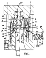
- FIG. 2 shows a longitudinal section through a device according to the invention, the upper half of the longitudinal section representing the locking position and the lower half of the longitudinal section representing the unlocking position.
- a piston 3 is slidably guided in a cylinder housing 1 and sealed against the cylinder wall of the cylinder housing 1 in the usual way via sealing rings and sliding rings.
- a pull rod 5 is arranged in the direction of arrow 9 coaxial to the center line 32 and is displaceable.
- the pull rod 5 can, as is otherwise the case with a piston rod of a fluid cylinder, be guided and sealed in the cylinder housing 1.
- the end of the pull rod 5 protruding into the cylinder space of the cylinder housing 1 has an annular channel 37 which delimits at least one end by a radially inward, preferably inclined surface 15 is. Due to its inclination, this inclined surface forms the outer surface of a truncated cone.
- Radially movable elements 13, preferably formed as ring segments, with a correspondingly inclined surface 26 are placed against this lateral surface 15.
- the angles of inclination of the surfaces are dimensioned such that a movement of the pull rod 5 in the direction of arrow 9 triggers a radially directed movement of the radially movable elements. This is particularly simple if the radially directed elements 13 are designed as balls.
- the radially movable elements are held in their axial positions by support means 17.
- these can be designed as an inner flange, this inner flange being arranged on an inner end face of the cylinder housing 1 and being equipped with an annular elevation as a spacer.
- the radially movable elements 13 are supported in the axial direction.
- the support ring of the support means 17 is dimensioned so that it does not exceed the outer envelope surface of the radially movable elements 13 in the position in which the radially movable elements 13 have moved the most radially inwards. This is shown particularly clearly by the enlarged detail according to FIG. 1.
- the piston 3 has an inner cavity into which the end of the pull rod 5 projects.
- the inner cavity is delimited in the radial direction by a conical surface 7 extending over a certain length in the axial direction, the angle of inclination 11 of which to the center line 32 forms an angle smaller than the self-locking angle. This angle then increases in the front end region, so that the cross section of this surface merges with the end surface 39 of the piston 3 in a hyperbolic manner.
- the radially movable element 13 insofar as it is designed as a circular ring segment, has an outer surface 25 which cooperates with the surface 7 of the piston 3 and which initially has the same angle of inclination as the angle 11 of the surface 7 of the piston 3. In the direction of the piston the inclination of the outer surface 25 then changes into an area 30 of greater inclination.
- the inner stroke range of the cylinder housing 1 for the piston 3 is limited by the inner cylinder base 35, against which the piston 3 comes to rest in the extreme release position, as the lower half of FIG. 2 shows. If, in this position, the pull rod 5 is simultaneously loaded by an external tensile force, the radially movable elements, regardless of whether balls or, as shown, circular ring segments, are driven radially outward because an axial movement is prevented by the support means 17. The radial outward movement is stopped in the radial direction by the piston 3, which, as the lower half of FIG. 2 shows, has reached its end position. The area 30 of greater inclination of each radially movable element 13 comes to rest against the approximately hyperbolic curved area of the inner surface 7 of the piston 3. A further radial movement is then no longer possible.
- the cylinder housing 1 can, for example, be provided with an inlet 40 for a flow medium. If the piston 3 moves in the opposite direction, the inlet 40 naturally acts as an outlet.
- the cylinder housing has a further inlet 41, through which a flow medium can likewise be introduced into the cylinder space of the cylinder housing 1 or through which the flow medium can be expelled when the piston 3 moves accordingly.
- a fluid can now be sent through the inlet 41 into the cylinder space of the cylinder housing 1 so that the piston 3 moves to the right out of the arrangement shown in FIG.
- a force is exerted on the radially movable elements 13.
- a corresponding triangle of forces is shown in FIG. 3.
- the force exerted on the radially movable elements 13 runs in the direction of the dashed force of the force triangle which is shown in FIG. 3.
- This force is divided into a radial and an axial component, so that the radially movable element 13 is forced radially inward by the radial component, whereas the axial component is caught by the support means 17.
- FIGS. 4 and 5 A structural variant is shown in Figures 4 and 5.
- This design also makes it possible, if necessary, to remove the associated pull rod 6 completely from the device, with the design according to FIGS. 4 and 5 simply pushing in this pull rod 6 triggers the device and causes the pull rod, as far as the outer ones components to be actuated allow this, is drawn in and the pull-in force is then maintained.
- a cylinder housing 2 is again used, in which a piston 4 is arranged to be displaceable in the direction of arrow 10.
- the piston 4 is designed as an annular piston and sealed against the cylinder wall of the cylinder housing 2 in the usual manner.
- Support means 18 protrude from the front into the cylinder housing and axially support elements 14 which are radially movable in the axial direction, similar to the way already described for the radially movable elements 13. These support elements 18 are also ring-shaped and are enclosed in the cylinder interior by an inner annular surface of the annular piston 4, the inner surface of the annular piston 4 being sealed against the outer annular surface of these supporting means 18.
- the embodiment of Figure 2 is designed such that the annular piston 4 is fluid-operated in the release direction, so that the cylinder housing 2 has a corresponding fluid inlet 42. In the clamping direction, the annular piston 4 is acted upon by elastic elements 19, which in the exemplary embodiment are designed as compression springs.
- This compression spring is supported on the one hand on the inner cylinder base 36 and on the other hand on an end face or recessed end face of the annular piston 4.
- the annular piston 4 has an inner surface 8, which with the center line 33 forms an angle 12 smaller than the self-locking angle. Starting from the end face of the annular piston, this surface 8 is followed by a short region of greater inclination, which merges into the cylindrical region of the annular piston 4, with which it is sealed on the outer cylinder wall of the support means 18.
- an axial bore 43 is provided, into which the pull rod 6 is inserted.
- the pull rod 6 has at its inner end in the manner already described in FIGS. 1 to 3 an annular channel 38 which is delimited towards the end of the pull rod 6 by a radially inwardly inclined surface 16.
- This inclined surface 16 in turn forms the outer surface of a truncated cone.
- each circular ring segment 14 has an outer surface 24 for cooperation with the corresponding surface 8 of the annular piston 4 and the adjoining short frustoconical surface with greater inclination.
- the latter is intended for cooperation with the correspondingly inclined surface 31 of the circular ring segment 14.
- the weakly inclined surface region of the surface 24 has an angle 29 on which the angle 12 corresponds to the surface 8 of the annular piston 4.
- Another element 20 projects axially coaxially into the cylinder space of the cylinder housing 4 and extends axially is arranged displaceably and is under the preload of elastic elements 44 which want to drive this further element 20 axially into the interior of the cylinder housing 4.
- An inner stop 45 ensures the limitation of this axial displacement. Due to the preload by the elastic elements 44, the end face 21 of the further element 20 remains in contact with the end face 22 of the pull rod 6 when it is in the tensioned position. This clamping position is shown in the left half of Figure 4.
- the annular piston 4 has been pushed forward by the elastic elements 19 in the axial direction (arrow 10) in the direction of the opening of the cylinder housing 2 and has initially over the surface area 31 of the circular ring segments 14 and subsequently in cooperation between the surfaces 8 of the annular piston 4 and the correspondingly inclined surface part of the surface 24 of the circular ring segment 14, all the circular ring segments 14 are displaced radially inward, so that in further cooperation between the surfaces 27 of the radially movable elements 14 and the surface 16 of the pull rod 6 these are pulled inwards and after reaching an external stop under tensile force is held.
- the device can now also be released and the pull rod 6 can be easily removed when the solution is complete.
- the annular piston 4 is acted upon at its corresponding end face via the inlet 42 with flow medium, so that the annular piston 4 moves inward against the force of the elastic elements 19. This can be done so far that the inner end face of the annular piston 4 comes to rest on the inner cylinder base 36.
- This allows the circular ring segments 14 to move radially outwards and finally assume the position shown on the right half in FIG. 4. This can be achieved in that a small tensile load is exerted on the pull rod 6 so that it wants to move outwards. Over the surface 27 of the circular ring segments 14, these are then moved radially outwards by contacting the surface 16 of the pull rod 6.
- the pull rod 6 is a receiving element of a tool in a tool carrier, the tool in the tool carrier being drawn up to a stop predetermined by the tool carrier and securely held there under preload, this pull rod 6 only has to be slightly pressed into the cylinder of the cylinder housing 2 are and will be completely drawn in immediately and locked while maintaining the preload.
- the locking is mechanically positive and therefore indissoluble and, as long as the release process is deliberately not switched, is retained regardless of any external influences.
Claims (12)
- Dispositif de serrage à actionnement pneumatique comportant :1.1 une enveloppe cylindrique (1, 2) avec fond de cylindre (35, 36);1.2 un Piston (3, 4) présentant une cavité intérieure, guidé coulissant dans l'enveloppe cylindrique (1, 2);1.3 une tige de traction (5, 6) pénétrant par une extrémité dans la cavité, coulissant coaxialement avec le piston (3, 4) et dépassant d'un côté de l'enveloppe cylindrique (1, 2), laquelle tige1.3.1 présente, dans cette section terminale intérieure, un canal annulaire (37, 38) continu qui possède une surface oblique (15, 16) montant vers l'extrémité libre intérieure de la tige de traction (5, 6) et qui forme une section tronconique de la tige de traction (5, 6) , ainsi que1.4. des éléments (13, 14) mobiles radialement, disposés entre la tige de traction (5, 6) et le piston (3, 4), dans la région du canal annulaire (37, 38) et qui coopèrent, par une surface extérieure (25, 24), avec une surface (7, 8) du piston (3, 4), inclinée vers l'intérieur dans le sens opposé à la surface oblique (15, 16), et coopèrent, par une surface intérieure (26, 27), avec la surface oblique (15, 16) et sont maintenus axialement par des moyens d'appui (17, 18) côté enveloppe,1.4.1. la surface intérieure (7, 8) du piston (3, 4) formant, au moins sur une partie de son extension longitudinale, dans le sens du coulissement (9, 10) de la tige de traction (5, 6), par rapport à la surface extérieure (25, 26) des éléments (13, 14), un angle (11,12) inférieur à l'angle d'autoblocage et1.5 le piston (3, 4), lors de sa course de serrage, produisant un déplacement, dirigé radialement vers l'intérieur des éléments (13, 14), du fait des surfaces coopérantes (7, 8; 25, 24) du piston ou des éléments (13, 14), le déplacement simultanément entrainant un déplacement en traction de la tige de traction (5, 6) dirigé vers l'intérieur, au moyen des surfaces coopérantes (26, 27; 15, 16) des éléments (13, 14) ou de la tige de traction (5, 6) et le piston (3, 4) autorisant, lors de son déplacement dans le sens du déverrouillage, dû à l'action du fluide sous pression, un déplacement des éléments (13, 14), dirigé radialement vers l'extérieur, ainsi qu'un rappel simultané de la tige de traction (5, 6) dans sa position initiale.
- Dispositif selon la Revendication 1, caractérisé en ce que le piston (4) est soumis à l'action d'un ressort (19) dans le sens du serrage.
- Dispositif selon la Revendication 1 ou 2, caractérisé en ce que coaxialement à la tige de traction (6), un autre élément (20) s'engage dans l'enveloppe cylindrique (2), sous précontrainte axiale et coulissant axialement vers la tige de traction (6) , pour s'appliquer, en vue d'un appui surfacique, par sa face frontale (21) contre la face frontale (22) correspondante de la tige de traction (6), l'autre élément (20) présentant au moins une surface (23) en vue de l'appui des éléments (14) mobiles radialement.
- Dispositif selon l'une des Revendications 1 à 3, caractérisé en ce que les éléments sont constitués par des billes ou des segments d'anneau circulaire (13, 14) présentant chacun une surface (24, 25) extérieure, correspondant à la surface (7, 8) du piston (3, 4) ainsi qu'une autre surface (26, 27) coopérant avec la surface (15, 16) de la tige de traction (5, 6).
- Dispositif selon la Revendication 4, caractérisé en ce que la ligne de section transversale de la surface extérieure des segments d'anneau circulaire (13, 14) forme, dans la région la plus extérieure par rapport au sens de coulissement de la tige de traction (5, 6), un angle (28, 29) inférieur à l'angle d'autoblocage auquel fait suite une région de plus forte pente.
- Dispositif selon l'une des Revendications 1 à 5, caractérisé en ce que la surface intérieure (7, 8) du piston (3, 4) présente une distance radiale augmentant vers la ligne médiane (32, 33) de la tige de traction (5, 6), dans le sens du déverrouillage.
- Dispositif selon la Revendication 6, caractérisé en ce que la surface d'enveloppe intérieure du piston (3) a la forme d'un hyperboloïde.
- Dispositif selon l'une des Revendications 1 à 7, caractérisé en ce que, dans chaque position extérieure radiale (Figure 3) des éléments (13) mobiles radialement la tangente (34) forme un angle, au point de contact de la surface intérieure (7) du piston (3) et de la surface extérieure (25) d'un segment (13) avec la perpendiculaire à la ligne médiane, angle qui est supérieur à l'angle d'autoblocage.
- Dispositif selon l'une des Revendications 1 à 8, caractérisé en ce que le dispositif présente une limitation de course pour le piston (3, 4).
- Dispositif selon la Revendication 9, caractérisé en ce que la limitation de course est telle qu'elle agit dans une position du piston dans laquelle les éléments (13, 14) mobiles radialement, dans leur position radiale la plus extérieure (Figure 3), présentent encore un recouvrement partiel avec la surface (15) dirigée radialement vers l'intérieur, de la tige de traction (5).
- Dispositif selon la Revendication 10, caractérisé en ce que la limitation de course est formée par le fond de cylindre (35, 36) de l'enveloppe cylindrique (1, 2).
- Dispositif selon l'une des Revendications 9 à 11, caractérisé en ce que la limitation de course est réglable.
Priority Applications (1)
| Application Number | Priority Date | Filing Date | Title |
|---|---|---|---|
| AT86103139T ATE64442T1 (de) | 1985-10-23 | 1986-03-08 | Druckmittelbetaetigte einrichtung. |
Applications Claiming Priority (2)
| Application Number | Priority Date | Filing Date | Title |
|---|---|---|---|
| DE3537687 | 1985-10-23 | ||
| DE3537687 | 1985-10-23 |
Publications (2)
| Publication Number | Publication Date |
|---|---|
| EP0219594A1 EP0219594A1 (fr) | 1987-04-29 |
| EP0219594B1 true EP0219594B1 (fr) | 1991-06-12 |
Family
ID=6284259
Family Applications (1)
| Application Number | Title | Priority Date | Filing Date |
|---|---|---|---|
| EP86103139A Expired - Lifetime EP0219594B1 (fr) | 1985-10-23 | 1986-03-08 | Dispositif actionné par fluide sous pression |
Country Status (4)
| Country | Link |
|---|---|
| US (1) | US4784044A (fr) |
| EP (1) | EP0219594B1 (fr) |
| AT (1) | ATE64442T1 (fr) |
| DE (1) | DE3679765D1 (fr) |
Cited By (1)
| Publication number | Priority date | Publication date | Assignee | Title |
|---|---|---|---|---|
| EP4046744A1 (fr) | 2021-02-23 | 2022-08-24 | Klaus-Dieter Klement Verwaltungs GmbH | Dispositif porteur, ainsi que procédé de fonctionnement d'un dispositif porteur |
Families Citing this family (24)
| Publication number | Priority date | Publication date | Assignee | Title |
|---|---|---|---|---|
| CH663826A5 (de) * | 1987-02-26 | 1988-01-15 | Bieri Ag Liebefeld H | Druckfluid beaufschlagbare, verriegelbare spannzylinder-kolbeneinheit. |
| DE3711808A1 (de) * | 1987-04-08 | 1988-10-20 | Walter Gmbh Montanwerke | Mehrteiliges spannsystem, insbesondere fuer rundlaufende werkzeuge |
| EP0297575A3 (fr) * | 1987-07-01 | 1990-03-28 | KRUEGER APPARATEBAU GMBH & CO. KG | Récepteur de courant pour le troisième rail |
| NL8702269A (nl) * | 1987-09-23 | 1989-04-17 | Applied Power Inc | Met een drukmedium te bekrachtigen zuiger-cilinderinrichting. |
| DE8904055U1 (fr) * | 1989-04-03 | 1989-09-07 | Klement, Klaus-Dieter, 5170 Juelich, De | |
| US5789719A (en) * | 1991-05-02 | 1998-08-04 | Milco Manufacturing Co. | Method and apparatus for electrical resistance spot welding |
| US5379969A (en) * | 1992-01-30 | 1995-01-10 | The Boeing Company | Hydraulic actuator with mechanical lock and installation |
| DE4330679A1 (de) * | 1993-09-10 | 1995-03-16 | Roehm Guenter H | Vorrichtung zur Betätigung eines Spannkopfes |
| DE19548711A1 (de) * | 1995-12-23 | 1997-07-03 | Klement Klaus Dieter | Schnittstelle zwischen einem Werkzeugträger und einem Spannschaft einer Werkzeugmaschine |
| JPH10277862A (ja) * | 1997-04-03 | 1998-10-20 | Sodick Co Ltd | 工作機械の工具保持具及び工具保持装置 |
| DE19748336C2 (de) * | 1997-11-01 | 2000-11-23 | Chiron Werke Gmbh | Maschinenzentrum, bei dem Werkstückhalter eine Mehrfachkupplung mit Abdeckung aufweisen |
| EP1262531B1 (fr) * | 2001-06-02 | 2005-12-14 | The Procter & Gamble Company | Procédé d'impréssion d'adhésif, article adhésif et rouleau par gravure |
| US7163740B2 (en) * | 2001-06-02 | 2007-01-16 | The Procter & Gamble Company | Process for printing adhesives, adhesive articles and printing equipment |
| DE10207415B4 (de) * | 2002-02-21 | 2014-01-16 | Narr Beteiligungs Gmbh | Hydraulischer oder pneumatischer Antrieb für einen Werkzeugspanner |
| DE102005018156B4 (de) * | 2005-04-20 | 2010-10-07 | Mundinger Engineering Gmbh | Kolbenzylinderanordnung mit einer Verriegelungsvorrichtung |
| GB0723822D0 (en) * | 2007-12-06 | 2008-01-16 | Expro North Sea Ltd | Piston assembly |
| DE102009050833A1 (de) * | 2009-10-19 | 2011-04-21 | Hydac Technology Gmbh | Vorrichtung zum impulsartigen Freigeben einer in einem Speichergehäuse bevorratbaren Fluidmenge |
| DE102009054929B4 (de) * | 2009-12-18 | 2022-08-11 | Robert Bosch Gmbh | Handwerkzeugmaschinenvorrichtung |
| DE102010000107A1 (de) | 2010-01-18 | 2011-07-21 | HYDROPNEU Fritz Daumüller GmbH, 73760 | Einrichtung mit einem Zylindergehäuse, einem Kolben und einer Kolbenstange |
| JP5841152B2 (ja) * | 2011-08-08 | 2016-01-13 | 株式会社コスメック | アクチュエータ及びそれを用いたクランプ装置 |
| AT12806U1 (de) * | 2011-11-25 | 2012-12-15 | Skardelly Thomas | Stellzylinder mit mechanischer ver-/entriegelung |
| ITUA20161397A1 (it) * | 2016-03-07 | 2017-09-07 | Ermanno Balzi S R L | Cilindro per il posizionamento di anime in uno stampo |
| FR3048822B1 (fr) * | 2016-03-11 | 2018-04-06 | Staubli Faverges | Raccord electrique |
| US10247210B2 (en) | 2017-02-10 | 2019-04-02 | Honeywell International Inc. | Hydraulic lock for thrust vector actuator |
Citations (1)
| Publication number | Priority date | Publication date | Assignee | Title |
|---|---|---|---|---|
| DE3018920A1 (de) * | 1980-05-17 | 1981-11-26 | Fa. Rolf Andexer, 4030 Ratingen | Verriegelung fuer druckzylinderkolben |
Family Cites Families (9)
| Publication number | Priority date | Publication date | Assignee | Title |
|---|---|---|---|---|
| US2741166A (en) * | 1950-05-18 | 1956-04-10 | William F Weirich | Device for cutting and forming slot insulation materials |
| DE2360337A1 (de) * | 1973-12-04 | 1975-06-05 | Deckel Ag Friedrich | Werkzeugspannvorrichtung |
| CA1016533A (en) * | 1974-05-24 | 1977-08-30 | Canadian Mine Services Ltd. | Drill head with locking chuck |
| US3967830A (en) * | 1975-11-03 | 1976-07-06 | The Theodore M. Smith Trust | Adjustable tension and/or compression tap holder |
| DE2910119A1 (de) * | 1979-03-15 | 1980-09-25 | Daimler Benz Ag | Durch servokraft betaetigter stellmotor |
| DE2911071C2 (de) * | 1979-03-21 | 1985-08-29 | 4515 Bad Essen Fa. Rolf Andexser | Verriegelung für Kolben von Druckmittelzylindern |
| DE3136311A1 (de) * | 1981-09-12 | 1983-04-21 | Festo-Maschinenfabrik Gottlieb Stoll, 7300 Esslingen | "druckmittelbetaetigter arbeitszylinder" |
| CA1197182A (fr) * | 1983-01-31 | 1985-11-26 | Koomey Blowout Preventers Inc. | Mecanisme d'actionnement a mouvement alternatif axial commande par fluide |
| DE3317487A1 (de) * | 1983-05-13 | 1984-11-15 | Gabrie, Duje Welter, 5170 Jülich | Zwangsverriegelungssystem fuer kolben von druckmittelzylindern |
-
1986
- 1986-03-08 EP EP86103139A patent/EP0219594B1/fr not_active Expired - Lifetime
- 1986-03-08 DE DE8686103139T patent/DE3679765D1/de not_active Expired - Lifetime
- 1986-03-08 AT AT86103139T patent/ATE64442T1/de not_active IP Right Cessation
- 1986-10-23 US US06/922,192 patent/US4784044A/en not_active Expired - Lifetime
Patent Citations (1)
| Publication number | Priority date | Publication date | Assignee | Title |
|---|---|---|---|---|
| DE3018920A1 (de) * | 1980-05-17 | 1981-11-26 | Fa. Rolf Andexer, 4030 Ratingen | Verriegelung fuer druckzylinderkolben |
Cited By (2)
| Publication number | Priority date | Publication date | Assignee | Title |
|---|---|---|---|---|
| EP4046744A1 (fr) | 2021-02-23 | 2022-08-24 | Klaus-Dieter Klement Verwaltungs GmbH | Dispositif porteur, ainsi que procédé de fonctionnement d'un dispositif porteur |
| DE102021104311A1 (de) | 2021-02-23 | 2022-08-25 | Klaus-Dieter Klement Verwaltungs Gmbh | Trägervorrichtung sowie Verfahren zum Betrieb einer Trägervorrichtung |
Also Published As
| Publication number | Publication date |
|---|---|
| DE3679765D1 (de) | 1991-07-18 |
| EP0219594A1 (fr) | 1987-04-29 |
| US4784044A (en) | 1988-11-15 |
| ATE64442T1 (de) | 1991-06-15 |
Similar Documents
| Publication | Publication Date | Title |
|---|---|---|
| EP0219594B1 (fr) | Dispositif actionné par fluide sous pression | |
| DE2741166C2 (de) | Vorrichtung zur Betätigung eines Spannkopfs | |
| EP0425773B1 (fr) | Dispositif de manoeuvre pour l'organe de fixation d'un outil ou d'une pièce dans la broche d'une machine outil | |
| DE2924707C2 (fr) | ||
| DE2101894B2 (de) | Spann- und Lösevorrichtung für Werkzeuge mit konischem Schaft an Werkzeugmaschinen mit umlaufender Werkzeugspindel | |
| EP0855243A2 (fr) | Dispositif de retenue, en particulier pour pièces à usiner | |
| DE1750270B1 (de) | Selbsttaetig und stufenlos wirkende mechanische Nachstellvorrichtung fuer eine Reibungsbremse,insbesondere eine Teilbelagscheibenbremse | |
| DE3732561C2 (fr) | ||
| DE3931014A1 (de) | Brems- oder/und klemmeinrichtung | |
| DE1296013B (de) | Hydraulischer Druckkolben | |
| EP0350516B1 (fr) | Dispositif de changement rapide de mandrins | |
| AT393302B (de) | Vorrichtung zur verbindung zweier werkzeugteile | |
| DE3925668C2 (de) | Gabelzinke mit Verlängerungsteil für einen Gabelstapler | |
| EP0446448B1 (fr) | Dispositif d'assemblage pour tuyaux sous pression ou équivalents | |
| EP1663555B1 (fr) | Dispositif de serrage | |
| DE2630891C3 (de) | Vorrichtung zum Verbinden eines mit einem Aufweitkonus versehenen Erdverdrängungshammers mit einem Nachziehrohr | |
| DE3611617C1 (de) | Vorrichtung zur Ioesbaren Arretierung eines Bolzens | |
| DE3810388A1 (de) | Vorrichtung zum festspannen eines linear bewegbaren, langgestreckten bauteils | |
| DE4124086A1 (de) | Vorrichtung zur betaetigung von backen, kernen oder aehnlichem als teile eines press- oder spritzwerkzeugs | |
| DE3230430C2 (de) | Spannvorrichtung zum Befestigen eines Werkzeughalters an einer hohlen Werkzeugspindel einer Wälzstoßmaschine | |
| DE1752698C3 (de) | Vorrichtung für den Längsvorschub eines schlanken, gegen Ausknicken zu sichernden Druckerzeugungsstempels für das hydrostatische Strangpressen o.dgl. Maschinenelementes bzw. Werkstückes | |
| DE2532330A1 (de) | Hydraulische spannelemente mit hydraulischem rueckzug | |
| WO1998006519A1 (fr) | Expanseur a dispositif de retour | |
| DE19727590C1 (de) | Crashkupplung für einen Überrollbügel in einem Kraftwagen | |
| EP0374091B1 (fr) | Dispositif d'abloquage pour le maintien temporaire d'un objet sur un support |
Legal Events
| Date | Code | Title | Description |
|---|---|---|---|
| PUAI | Public reference made under article 153(3) epc to a published international application that has entered the european phase |
Free format text: ORIGINAL CODE: 0009012 |
|
| AK | Designated contracting states |
Kind code of ref document: A1 Designated state(s): AT BE CH DE FR GB IT LI NL |
|
| 17P | Request for examination filed |
Effective date: 19870728 |
|
| 17Q | First examination report despatched |
Effective date: 19880105 |
|
| GRAA | (expected) grant |
Free format text: ORIGINAL CODE: 0009210 |
|
| AK | Designated contracting states |
Kind code of ref document: B1 Designated state(s): AT BE CH DE FR GB IT LI NL |
|
| PG25 | Lapsed in a contracting state [announced via postgrant information from national office to epo] |
Ref country code: BE Effective date: 19910612 |
|
| REF | Corresponds to: |
Ref document number: 64442 Country of ref document: AT Date of ref document: 19910615 Kind code of ref document: T |
|
| REF | Corresponds to: |
Ref document number: 3679765 Country of ref document: DE Date of ref document: 19910718 |
|
| ITF | It: translation for a ep patent filed |
Owner name: DR. ING. A. RACHELI & C. |
|
| ET | Fr: translation filed | ||
| GBT | Gb: translation of ep patent filed (gb section 77(6)(a)/1977) | ||
| PG25 | Lapsed in a contracting state [announced via postgrant information from national office to epo] |
Ref country code: AT Effective date: 19920308 |
|
| PLBE | No opposition filed within time limit |
Free format text: ORIGINAL CODE: 0009261 |
|
| STAA | Information on the status of an ep patent application or granted ep patent |
Free format text: STATUS: NO OPPOSITION FILED WITHIN TIME LIMIT |
|
| 26N | No opposition filed | ||
| REG | Reference to a national code |
Ref country code: GB Ref legal event code: IF02 |
|
| PGFP | Annual fee paid to national office [announced via postgrant information from national office to epo] |
Ref country code: DE Payment date: 20050211 Year of fee payment: 20 |
|
| PGFP | Annual fee paid to national office [announced via postgrant information from national office to epo] |
Ref country code: GB Payment date: 20050228 Year of fee payment: 20 |
|
| PGFP | Annual fee paid to national office [announced via postgrant information from national office to epo] |
Ref country code: CH Payment date: 20050310 Year of fee payment: 20 |
|
| PGFP | Annual fee paid to national office [announced via postgrant information from national office to epo] |
Ref country code: FR Payment date: 20050311 Year of fee payment: 20 |
|
| PGFP | Annual fee paid to national office [announced via postgrant information from national office to epo] |
Ref country code: IT Payment date: 20050316 Year of fee payment: 20 |
|
| PGFP | Annual fee paid to national office [announced via postgrant information from national office to epo] |
Ref country code: NL Payment date: 20050322 Year of fee payment: 20 |
|
| PG25 | Lapsed in a contracting state [announced via postgrant information from national office to epo] |
Ref country code: GB Free format text: LAPSE BECAUSE OF EXPIRATION OF PROTECTION Effective date: 20060307 |
|
| PG25 | Lapsed in a contracting state [announced via postgrant information from national office to epo] |
Ref country code: NL Free format text: LAPSE BECAUSE OF EXPIRATION OF PROTECTION Effective date: 20060308 |
|
| REG | Reference to a national code |
Ref country code: GB Ref legal event code: PE20 |
|
| REG | Reference to a national code |
Ref country code: CH Ref legal event code: PL |
|
| NLV7 | Nl: ceased due to reaching the maximum lifetime of a patent |
Effective date: 20060308 |