EP0847924B1 - Faltvorrichtung zum Einschlagen von schmalen Stirnseitenlappen einer Folienhülle eines Zigarettenblocks - Google Patents
Faltvorrichtung zum Einschlagen von schmalen Stirnseitenlappen einer Folienhülle eines Zigarettenblocks Download PDFInfo
- Publication number
- EP0847924B1 EP0847924B1 EP97121033A EP97121033A EP0847924B1 EP 0847924 B1 EP0847924 B1 EP 0847924B1 EP 97121033 A EP97121033 A EP 97121033A EP 97121033 A EP97121033 A EP 97121033A EP 0847924 B1 EP0847924 B1 EP 0847924B1
- Authority
- EP
- European Patent Office
- Prior art keywords
- folding
- end side
- figur
- lifting platform
- folding device
- Prior art date
- Legal status (The legal status is an assumption and is not a legal conclusion. Google has not performed a legal analysis and makes no representation as to the accuracy of the status listed.)
- Expired - Lifetime
Links
Images


Classifications
-
- B—PERFORMING OPERATIONS; TRANSPORTING
- B65—CONVEYING; PACKING; STORING; HANDLING THIN OR FILAMENTARY MATERIAL
- B65B—MACHINES, APPARATUS OR DEVICES FOR, OR METHODS OF, PACKAGING ARTICLES OR MATERIALS; UNPACKING
- B65B49/00—Devices for folding or bending wrappers around contents
- B65B49/08—Reciprocating or oscillating folders
Definitions
- the invention relates to a folding device for turning in narrow end flaps on partially encased packing blocks made of rod-shaped articles the tobacco-processing industry, with a packaging block that receives the communicating on the top with receiving pockets of a turntable Lifting platform.
- Devices of the type mentioned are part of several in succession tools used to manufacture a so-called Head closure on a foil wrap enveloping a cigarette block, the subsequent packaging operations with an external wrap, for example provided in the form of a so-called hinged lid pack becomes.
- the invention has for its object to qualitatively the head-closing folds improve and optimally in the processing step and the associated transfer steps to integrate the packing blocks.
- This object is achieved according to the invention by means of a support surface which can be moved into the stroke path between the lifting platform and the receiving pockets of the turntable and cooperates with folding members which act on the end flaps.
- a support surface which can be moved into the stroke path between the lifting platform and the receiving pockets of the turntable and cooperates with folding members which act on the end flaps.
- the folding members are expediently designed as turning twists for turning in the narrow end flaps.
- exact positioning of the packing blocks relative to the folding members or to the respective receiving pocket of the turntable is ensured by the fact that the lifting platform is part of a folding chamber which is open on the top side and on one end face.
- the folds produced by the rotary impactors receive a sharp-edged expression according to a further proposal in that the rotary impactors interact with ironing plates placed on the top and bottom.
- the advantage achieved by the invention is that when the narrow end flaps fixed the film on its broad side to the cigarette block so that it cannot bulge during folding. In this way exact, sharp-edged head closing folds are guaranteed.
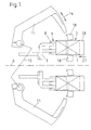
- each case two receiving pockets 3 of such a turntable, which is common to both tracks of the packaging device, communicate simultaneously with two folding chambers 4 arranged on both sides of the line of symmetry 6.
- the folding chamber 4 is open on the upper side and on an end face which allows the packing blocks 2 to be opened, and is delimited on the bottom side by a lifting platform 8 which can be moved in the direction of the double arrow 7.
- the stop side of the folding chamber 4 opposite the inlet side is perforated in a manner not shown for receiving a transfer or stop tappet 9.
- a swivel guide 11 with a support surface 12 for the upper side of the inner wrap 1 of the packing block 2 can be swiveled into the space between the receiving pocket 3 and the folding chamber 4, which space comprises part of the lifting path of the lifting platform 8.
- the double-sided swivel guides 11 for both tracks can be moved together in the direction of the double arrow 14 by means of a coupling connection 13, which is only indicated schematically, by a swivel drive (not shown).
- the receiving pocket 3 is assigned a lifting stop 17 which can be moved up and down in the direction of the double arrow 16 for transferring a packing block 2 from the folding chamber 4 into the receiving pocket 3.
- folding members in the form of rotary wrappers 18 are provided on the open end face of the folding chamber 4 for turning in the narrow end flaps 19 of the inner wrapper 1.
- the rotary impactors 18 are assigned top and bottom bracket plates 21.
- an up and down are to complete the head-closing folds movable lower folder 22 for turning in the wide lower front lobe 23 as well as a stationary upper folder 24 for turning in the broad front lobe 26 provided.
- the mode of operation for executing the head-closing folds or for completing the inner wrap 1 until the packing block 2 is transferred into a receiving pocket 3 of the turntable is as follows: According to FIGS. 1 to 5, the packing block 2 with the inside wrap 1 open at the end is transferred in the direction of arrow 27 through a push rod, not shown, to the lifting platform 8 of the folding chamber 4, the ironing plates 21 being set against the packing block 2 for top and bottom guidance. In synchronism with this insertion movement, the stop plunger 9 resting on the opposite end face of the packing block 2 is moved back in the direction of the arrow 27, thus ensuring a tied transfer.
- the pivot guide 11 is pivoted inwards according to FIGS. 4 and 5 and, with its support surface 12 resting on the packing block 2, takes over the top-side guidance following the bracket plate 21.
- the head closure is in the state shown in FIG. 9.
- the folded edges of the folded-in end flaps 19 are given a sharp-edged shape in that, according to FIG. 10, the ironing plates 21 are placed on the top and bottom of the swiveled-in rotary insert 21 and thereby compress the folded edges.
- the ironing plates 21 are lifted off and set back again and, according to FIG. 12, the lower folder 22 is moved upward, so that the front lower lobe 23 is turned in according to FIG. 13.
- the swivel guide 11 has returned to the position shown in FIG.
Landscapes
- Engineering & Computer Science (AREA)
- Mechanical Engineering (AREA)
- Wrapping Of Specific Fragile Articles (AREA)
- Basic Packing Technique (AREA)
Description
Insbesondere in Verbindung mit einer Maschine zur gleichzeitigen Herstellung von zwei parallelen Packungssträngen bietet sich eine vorteilhafte Weiterbildung an, gemäß der die Stützfläche als in den Hubraum bzw. die Überführungsbahn einschwenkende Schwenkführung ausgebildet ist.
Die durch die Dreheinschläger erzeugten Faltungen erhalten eine scharfkantige Ausprägung nach einem weiteren Vorschlag dadurch, daß die Dreheinschläger mit ober- und unterseitig aufsetzenden Bügelplatten zusammenwirken.
- Figur 1
- eine Faltvorrichtung gemäß Erfindung in Verbindung mit einer doppelbahnigen Verpackungseinrichtung für Zigarettenblöcke in der Draufsicht,
- Figur 2
- ein der erfindungsgemäßen Faltvorrichtung zugeführter, teilumhüllter bzw. stirnseitig offener Zigarettenblock,
- Figur 3
- eine Seitenansicht auf eine der Figur 1 entsprechende Überführungsstellung der Zigarettenblöcke entlang der einen Bahn,
- Figur 4
- eine Draufsicht auf eine Schwenkführung in der Arbeitsstellung,
- Figur 5
- eine Seitenansicht auf die zwischen einer Faltkammer und einer Aufnahmetasche eines Drehtellers eingeschwenkte Schwenkführung gemäß Figur 4,
- Figur 6
- eine stirnseitige Ansicht auf in ihrer Arbeitsstellung eingeschwenkte Faltorgane zum Einschlagen der Stirnseitenlappen,
- Figur 7
- eine Seitenansicht auf die in der Arbeitsstellung befindlichen Faltorgane gemäß Figur 6,
- Figur 8
- eine Draufsicht auf die in der Arbeitsstellung befindlichen Faltorgane gemäß Figur 6,
- Figur 9
- einen Packungsblock nach erfolgtem Stirnseiteneinschlag des Kopfschlusses,
- Figuren 10 und 11
- unterschiedliche Arbeitsstellungen von Falthilfsorganen in der Seitenansicht,
- Figur 12
- eine Seitenansicht auf ein weiteres Faltorgan in der Arbeitsstellung,
- Figur 13
- eine Darstellung des Packungsblocks nach erfolgter Teilfaltung des Kopfschlusses gemäß Figur 12,
- Figur 14
- eine Seitenansicht auf eine Arbeitsstellung eines Überführungsorgans mit zugeordneten zusätzlichen Faltorganen,
- Figur 15
- eine Arbeitsstellung des Überführungsorgans nach erfolgter Überführung eines Packungsblocks aus der Faltkammer in eine Aufnahmetasche des Drehtellers und
- Figur 16
- eine Ansicht des gemäß Figur 15 vollendeten Kopfschlusses des Packungsblocks.
Die Faltkammer 4 ist oberseitig und an einer die Packungsblöcke 2 einlassenden Stirnseite offen und bodenseitig durch eine in Richtung des Doppelpfeils 7 bewegbare Hubplattform 8 begrenzt. Die der Einlaßseite gegenüberliegende Anschlagseite der Faltkammer 4 ist zur Aufnahme eines Überführungs- bzw. Anschlagstößels 9 auf nicht gezeigte Weise durchbrochen.
In den einen Teil des Hubweges der Hubplattform 8 umfassenden Zwischenraum zwischen der Aufnahmetasche 3 und der Faltkammer 4 ist eine Schwenkführung 11 mit einer Stützfläche 12 für die Oberseite des Inneneinschlags 1 des Packungsblocks 2 hineinschwenkbar. Die doppelseitigen Schwenkführungen 11 für beide Bahnen sind mittels einer lediglich schematisch angedeuteten Koppelverbindung 13 durch einen nicht dargestellten Schwenkantrieb gemeinsam in Richtung des Doppelpfeils 14 bewegbar.
Der Aufnahmetasche 3 ist ein in Richtung des Doppelpfeils 16 auf- und abbewegbarer Hubanschlag 17 zum Überführen eines Packungsblocks 2 aus der Faltkammer 4 in die Aufnahmetasche 3 zugeordnet.
Des weiteren sind Faltorgane in Form von Dreheinschlägern 18 an der offenen Stirnseite der Faltkammer 4 vorgesehen zum Einschlagen der schmalen Stirnseitenlappen 19 des Inneneinschlags 1.
Gemäß den Figuren 1 bis 5 wird der Packungsblock 2 mit dem stirnseitig offenen Inneneinschlag 1 in Pfeilrichtung 27 durch einen nicht dargestellten Schubstößel auf die Hubplattform 8 der Faltkammer 4 überführt, wobei zur ober- und unterseitigen Führung die Bügelplatten 21 gegen den Packungsblock 2 angestellt sind. Synchron mit dieser Einschubbewegung wird der an der entgegengesetzten Stirnseite des Packungsblocks 2 anliegende Anschlagstößel 9 in Pfeilrichtung 27 zurückbewegt, womit eine gefesselte Überführung gewährleistet ist. Bereits während dieser Überführung wird die Schwenkführung 11 gemäß den Figuren 4 und 5 einwärtsgeschwenkt und übernimmt mit ihrer auf dem Packungsblock 2 aufliegenden Stützfläche 12 im Anschluß an die Bügelplatte 21 die oberseitige Führung.
Die Faltkanten der eingefalteten Stirnseitenlappen 19 erhalten eine scharfkantige Form dadurch, daß gemäß Figur 10 die Bügelplatten 21 ober- und unterseitig an die eingeschwenkten Dreheinschläger 21 angelegt werden und dabei die Faltkanten zusammenpressen.
Anschließend werden gemäß Figur 11 die Bügelplatten 21 wieder abgehoben und zurückgesetzt und gemäß Figur 12 der Unterfalter 22 nach oben bewegt, so daß der Stirnunterlappen 23 gemäß Figur 13 eingeschlagen wird.
Inzwischen ist die Schwenkführung 11 in die in Figur 1 gezeigte Stellung zurückgegekehrt und damit der Raum zwischen der Aufnahmetasche 3 und der Faltkammer 4 freigegeben, so daß gemäß Figur 14 der Hubanschlag 17 gegen den Packungsblock 2 herunterbewegt werden kann. Durch anschließende gemeinsame Aufwärtsbewegung von Hubplattform 8 und Hubanschlag 17 gemäß Figur 15 wird der Packungsblock 2 aus der Faltkammer 4 in die Aufnahmetasche 3 überführt, wobei der Stirnoberlappen 26 durch den ortsfesten Oberfalter 24 eingeschlagen wird, womit gemäß Figur 16 der Kopfschluß des Inneneinschlags 1 vollendet ist.
Claims (5)
- Faltvorrichtung zum Einschlagen von schmalen Stirnseitenlappen an teilweise umhüllten Packungsblöcken aus stabförmigen Artikeln der tabakverarbeitenden Industrie, mit einer die Packungsblöcke breitseitig aufnehmenden, oberseitig mit Aufnahmetaschen eines Drehtellers kommunizierenden Hubplattform, gekennzeichnet durch eine in den Hubweg zwischen der Hubplattform (8) und den Aufnahmetaschen (3) des Drehtellers hineinbewegbare, mit die Stirnseitenlappen (19) beaufschlagenden Faltorganen (18) zusammenwirkende Stützfläche (12).
- Faltvorrichtung nach Anspruch 1, dadurch gekennzeichnet, daß die Stützfläche (12) als in den Hubweg bzw. die Überführungsbahn einschwenkende Schwenkführung (11) ausgebildet ist.
- Faltvorrichtung nach Anspruch 1 oder 2, dadurch gekennzeichnet, daß die Faltorgane (18) als Dreheinschläger ausgebildet sind.
- Faltvorrichtung nach einem der Ansprüche 1 bis 3, dadurch gekennzeichnet, daß die Hubplattform (8) Teil einer oberseitig sowie an einer Stirnseite offenen Faltkammer (4) ist.
- Faltvorrichtung nach einem der Ansprüche 3 oder 4, dadurch gekennzeichnet, daß die Dreheinschläger (18) mit ober- und unterseitig aufsetzenden Bügelplatten (21) zusammenwirken.
Applications Claiming Priority (2)
| Application Number | Priority Date | Filing Date | Title |
|---|---|---|---|
| DE19651874 | 1996-12-13 | ||
| DE19651874A DE19651874A1 (de) | 1996-12-13 | 1996-12-13 | Faltvorrichtung zum Einschlagen von schmalen Stirnseitenlappen an Packungsblöcken der tabakverarbeitenden Industrie |
Publications (2)
| Publication Number | Publication Date |
|---|---|
| EP0847924A1 EP0847924A1 (de) | 1998-06-17 |
| EP0847924B1 true EP0847924B1 (de) | 2000-07-26 |
Family
ID=7814592
Family Applications (1)
| Application Number | Title | Priority Date | Filing Date |
|---|---|---|---|
| EP97121033A Expired - Lifetime EP0847924B1 (de) | 1996-12-13 | 1997-11-29 | Faltvorrichtung zum Einschlagen von schmalen Stirnseitenlappen einer Folienhülle eines Zigarettenblocks |
Country Status (6)
| Country | Link |
|---|---|
| US (1) | US5819501A (de) |
| EP (1) | EP0847924B1 (de) |
| JP (1) | JPH10297608A (de) |
| CN (1) | CN1087257C (de) |
| DE (2) | DE19651874A1 (de) |
| ES (1) | ES2149540T3 (de) |
Families Citing this family (6)
| Publication number | Priority date | Publication date | Assignee | Title |
|---|---|---|---|---|
| JP4038601B2 (ja) * | 1998-10-29 | 2008-01-30 | 四国化工機株式会社 | 包装機械 |
| DE19852693A1 (de) * | 1998-11-16 | 2000-05-18 | Focke & Co | Weichpackung für Zigaretten sowie Verfahren und Vorrichtung zum Herstellen derselben |
| DE102010018238A1 (de) | 2010-04-23 | 2011-10-27 | Focke & Co. (Gmbh & Co. Kg) | Vorrichtung und Verfahren zum Herstellen von Packungen für Zigaretten |
| US20140360138A1 (en) * | 2013-06-07 | 2014-12-11 | Chris Allen Honegger | Apparatus and method for closing and sealing bags in bale enveloping apparatus |
| DE102019120788A1 (de) * | 2019-08-01 | 2021-02-04 | Khs Gmbh | Vorrichtung sowie Verfahren für die Herstellung von Gebinden aus Einzelpackungen |
| CN111483657B (zh) * | 2020-04-29 | 2021-06-08 | 山东华绿保节能环保科技有限公司 | 一种真空保温板包装机 |
Family Cites Families (9)
| Publication number | Priority date | Publication date | Assignee | Title |
|---|---|---|---|---|
| FR953205A (fr) * | 1946-08-26 | 1949-12-02 | Oxo Ltd | Machine à envelopper |
| GB985185A (en) * | 1962-12-13 | 1965-03-03 | Molins Organisation Ltd | Improvements in or relating to packing machinery |
| DE3712717A1 (de) * | 1987-04-14 | 1988-11-03 | Schmermund Maschf Alfred | Bodenfaltungspacker |
| DE3929982C1 (de) * | 1989-09-08 | 1991-02-28 | Maschinenfabrik Alfred Schmermund Gmbh & Co, 5820 Gevelsberg, De | |
| JPH0472123A (ja) * | 1990-07-02 | 1992-03-06 | Mitsubishi Heavy Ind Ltd | 弾性のある不定形品の包装方法および包装装置 |
| IT1242228B (it) * | 1990-10-18 | 1994-03-03 | Sasib Spa | Macchina impacchettatrice di sigarette, in particolare in pacchetti rigidi con coperchio a cerniera |
| ITBO940213A1 (it) * | 1994-05-16 | 1995-11-16 | Gd Spa | Metodo per la realizzazione di stecche di sigarette con involucro rigido del tipo a coperchio incernierato. |
| IT1280370B1 (it) * | 1995-02-21 | 1998-01-20 | Gd Spa | Macchina impacchettatrice continua di sigarette |
| IT1281260B1 (it) * | 1995-04-27 | 1998-02-17 | Sasib Spa | Metodo e dispositivo per imballare prodotti, in particolare astiformi, come sigarette, o simili in un foglio d'involucro |
-
1996
- 1996-12-13 DE DE19651874A patent/DE19651874A1/de not_active Withdrawn
-
1997
- 1997-11-26 US US08/978,994 patent/US5819501A/en not_active Expired - Fee Related
- 1997-11-29 DE DE59702078T patent/DE59702078D1/de not_active Expired - Fee Related
- 1997-11-29 EP EP97121033A patent/EP0847924B1/de not_active Expired - Lifetime
- 1997-11-29 ES ES97121033T patent/ES2149540T3/es not_active Expired - Lifetime
- 1997-12-12 JP JP9343279A patent/JPH10297608A/ja not_active Withdrawn
- 1997-12-12 CN CN97125539A patent/CN1087257C/zh not_active Expired - Fee Related
Also Published As
| Publication number | Publication date |
|---|---|
| DE59702078D1 (de) | 2000-08-31 |
| HK1010522A1 (en) | 1999-06-25 |
| DE19651874A1 (de) | 1998-06-18 |
| US5819501A (en) | 1998-10-13 |
| CN1087257C (zh) | 2002-07-10 |
| EP0847924A1 (de) | 1998-06-17 |
| JPH10297608A (ja) | 1998-11-10 |
| CN1184755A (zh) | 1998-06-17 |
| ES2149540T3 (es) | 2000-11-01 |
Similar Documents
| Publication | Publication Date | Title |
|---|---|---|
| EP1103465B1 (de) | Verfahren und Vorrichtung zum Herstellen von Klappschachteln für Zigaretten | |
| DE3123496C2 (de) | ||
| DE2440006A1 (de) | Verfahren und vorrichtung zum herstellen und fuellen von klappschachteln aus faltbarem werkstoff, vorzugsweise fuer zigaretten | |
| EP1448443A1 (de) | Verfahren und vorrichtung zum herstellen von hartpackungen für zigaretten | |
| EP3194276A1 (de) | Verfahren und vorrichtung zum herstellen von packungen für zigaretten | |
| DE60013499T2 (de) | Verpackung für eine Gruppe von länglichen Gegenständen und Herstellungsmethoden | |
| EP2311632A1 (de) | Zigarettenpackung sowie Verfahren und Vorrichtung zum Herstellen derselben | |
| EP0856467B1 (de) | Verfahren und Vorrichtung zum Zusammenführen und Zusammenfügen von Schachtelzuschnitten und blockförmigen Artikelgruppen | |
| EP0054284B1 (de) | Maschine zum Herstellen, Füllen und Verschliessen von Packungen | |
| DE2545256C2 (de) | Vorrichtung zum Herstellen bzw. Schließen von Packungen, insbesondere quaderförmigen Zigaretten-Packungen | |
| DE3728716A1 (de) | Verfahren und vorrichtung zum einhuellen von insbesondere zigaretten-packungen | |
| DE60127485T2 (de) | Verfahren und Vorrichtung zum Herstellen von Klappdeckelverpackungen für Zigaretten | |
| DE3639982C2 (de) | ||
| EP2647576B1 (de) | Vorrichtung und verfahren zum herstellen von packungen für zigaretten | |
| EP2130773A1 (de) | Verfahren und Vorrichtung zum Herstellen von Zigarettenpackungen | |
| EP0847924A1 (de) | Faltvorrichtung zum Einschlagen von schmalen Stirnseitenlappen einer Folienhülle eines Zigarettenblocks | |
| EP1116660B1 (de) | Vorrichtung zum Herstellen von Gebindepackungen für Zigaretten | |
| EP1023991B1 (de) | Verfahren und Vorrichtung zum Herstellen von Zigarettenpackungen | |
| EP2429903A1 (de) | Verfahren und vorrichtung zum herstellen von (zigaretten-)packungen | |
| DE10053666A1 (de) | Verfahren und Einrichtung zum Umhüllen von Verpackungen von Produkten der tabakverarbeitenden Industrie | |
| DE2613277A1 (de) | Quaderfoermige packung sowie verfahren und vorrichtung zum herstellen derselben | |
| EP0786406B1 (de) | Verfahren und Vorrichtung zum Überführen eines Kragenzuschnitts für eine Zigarettenpackung in eine Aufnahmetasche eines Verpackungsförderers | |
| DE1277104B (de) | Vorrichtung zum Einfalten der Verschlusslaschen von Faltkartons | |
| DE3538264A1 (de) | Stangenpacker zum verpacken von zigarettenpackungen und dergl. | |
| DE2462686C2 (de) | Vorrichtung zum Zuführen von insbesondere Zigarettengruppen zu einer Packung o.dgl. |
Legal Events
| Date | Code | Title | Description |
|---|---|---|---|
| PUAI | Public reference made under article 153(3) epc to a published international application that has entered the european phase |
Free format text: ORIGINAL CODE: 0009012 |
|
| AK | Designated contracting states |
Kind code of ref document: A1 Designated state(s): BE CH DE ES FR GB IT LI NL |
|
| AX | Request for extension of the european patent |
Free format text: AL;LT;LV;MK;RO;SI |
|
| 17P | Request for examination filed |
Effective date: 19981127 |
|
| AKX | Designation fees paid |
Free format text: BE CH DE ES FR GB IT LI NL |
|
| RBV | Designated contracting states (corrected) |
Designated state(s): BE CH DE ES FR GB IT LI NL |
|
| GRAG | Despatch of communication of intention to grant |
Free format text: ORIGINAL CODE: EPIDOS AGRA |
|
| 17Q | First examination report despatched |
Effective date: 19990922 |
|
| GRAG | Despatch of communication of intention to grant |
Free format text: ORIGINAL CODE: EPIDOS AGRA |
|
| GRAH | Despatch of communication of intention to grant a patent |
Free format text: ORIGINAL CODE: EPIDOS IGRA |
|
| GRAH | Despatch of communication of intention to grant a patent |
Free format text: ORIGINAL CODE: EPIDOS IGRA |
|
| GRAA | (expected) grant |
Free format text: ORIGINAL CODE: 0009210 |
|
| ITF | It: translation for a ep patent filed | ||
| AK | Designated contracting states |
Kind code of ref document: B1 Designated state(s): BE CH DE ES FR GB IT LI NL |
|
| REG | Reference to a national code |
Ref country code: CH Ref legal event code: EP |
|
| GBT | Gb: translation of ep patent filed (gb section 77(6)(a)/1977) |
Effective date: 20000726 |
|
| REF | Corresponds to: |
Ref document number: 59702078 Country of ref document: DE Date of ref document: 20000831 |
|
| ET | Fr: translation filed | ||
| REG | Reference to a national code |
Ref country code: ES Ref legal event code: FG2A Ref document number: 2149540 Country of ref document: ES Kind code of ref document: T3 |
|
| PG25 | Lapsed in a contracting state [announced via postgrant information from national office to epo] |
Ref country code: BE Free format text: LAPSE BECAUSE OF NON-PAYMENT OF DUE FEES Effective date: 20001130 |
|
| BERE | Be: lapsed |
Owner name: TOPACK VERPACKUNGSTECHNIK G.M.B.H. Effective date: 20001130 |
|
| PLBE | No opposition filed within time limit |
Free format text: ORIGINAL CODE: 0009261 |
|
| STAA | Information on the status of an ep patent application or granted ep patent |
Free format text: STATUS: NO OPPOSITION FILED WITHIN TIME LIMIT |
|
| 26N | No opposition filed | ||
| REG | Reference to a national code |
Ref country code: GB Ref legal event code: IF02 |
|
| PGFP | Annual fee paid to national office [announced via postgrant information from national office to epo] |
Ref country code: ES Payment date: 20030905 Year of fee payment: 7 |
|
| PGFP | Annual fee paid to national office [announced via postgrant information from national office to epo] |
Ref country code: GB Payment date: 20031027 Year of fee payment: 7 |
|
| PGFP | Annual fee paid to national office [announced via postgrant information from national office to epo] |
Ref country code: FR Payment date: 20031120 Year of fee payment: 7 |
|
| PGFP | Annual fee paid to national office [announced via postgrant information from national office to epo] |
Ref country code: CH Payment date: 20031124 Year of fee payment: 7 |
|
| PGFP | Annual fee paid to national office [announced via postgrant information from national office to epo] |
Ref country code: NL Payment date: 20031125 Year of fee payment: 7 |
|
| PGFP | Annual fee paid to national office [announced via postgrant information from national office to epo] |
Ref country code: DE Payment date: 20031204 Year of fee payment: 7 |
|
| PG25 | Lapsed in a contracting state [announced via postgrant information from national office to epo] |
Ref country code: GB Free format text: LAPSE BECAUSE OF NON-PAYMENT OF DUE FEES Effective date: 20041129 |
|
| PG25 | Lapsed in a contracting state [announced via postgrant information from national office to epo] |
Ref country code: LI Free format text: LAPSE BECAUSE OF NON-PAYMENT OF DUE FEES Effective date: 20041130 Ref country code: ES Free format text: LAPSE BECAUSE OF NON-PAYMENT OF DUE FEES Effective date: 20041130 Ref country code: CH Free format text: LAPSE BECAUSE OF NON-PAYMENT OF DUE FEES Effective date: 20041130 |
|
| PG25 | Lapsed in a contracting state [announced via postgrant information from national office to epo] |
Ref country code: NL Free format text: LAPSE BECAUSE OF NON-PAYMENT OF DUE FEES Effective date: 20050601 Ref country code: DE Free format text: LAPSE BECAUSE OF NON-PAYMENT OF DUE FEES Effective date: 20050601 |
|
| REG | Reference to a national code |
Ref country code: CH Ref legal event code: PL |
|
| GBPC | Gb: european patent ceased through non-payment of renewal fee |
Effective date: 20041129 |
|
| PG25 | Lapsed in a contracting state [announced via postgrant information from national office to epo] |
Ref country code: FR Free format text: LAPSE BECAUSE OF NON-PAYMENT OF DUE FEES Effective date: 20050729 |
|
| NLV4 | Nl: lapsed or anulled due to non-payment of the annual fee |
Effective date: 20050601 |
|
| REG | Reference to a national code |
Ref country code: FR Ref legal event code: ST |
|
| PG25 | Lapsed in a contracting state [announced via postgrant information from national office to epo] |
Ref country code: IT Free format text: LAPSE BECAUSE OF NON-PAYMENT OF DUE FEES Effective date: 20051129 |
|
| REG | Reference to a national code |
Ref country code: ES Ref legal event code: FD2A Effective date: 20041130 |