EP0846797B1 - Kettenwirkmaschine mit Jacquard-Legebarre - Google Patents
Kettenwirkmaschine mit Jacquard-Legebarre Download PDFInfo
- Publication number
- EP0846797B1 EP0846797B1 EP97120683A EP97120683A EP0846797B1 EP 0846797 B1 EP0846797 B1 EP 0846797B1 EP 97120683 A EP97120683 A EP 97120683A EP 97120683 A EP97120683 A EP 97120683A EP 0846797 B1 EP0846797 B1 EP 0846797B1
- Authority
- EP
- European Patent Office
- Prior art keywords
- knitting machine
- warp knitting
- machine according
- needle
- bending transducers
- Prior art date
- Legal status (The legal status is an assumption and is not a legal conclusion. Google has not performed a legal analysis and makes no representation as to the accuracy of the status listed.)
- Expired - Lifetime
Links
Images

Classifications
-
- D—TEXTILES; PAPER
- D04—BRAIDING; LACE-MAKING; KNITTING; TRIMMINGS; NON-WOVEN FABRICS
- D04B—KNITTING
- D04B21/00—Warp knitting processes for the production of fabrics or articles not dependent on the use of particular machines; Fabrics or articles defined by such processes
-
- D—TEXTILES; PAPER
- D04—BRAIDING; LACE-MAKING; KNITTING; TRIMMINGS; NON-WOVEN FABRICS
- D04B—KNITTING
- D04B27/00—Details of, or auxiliary devices incorporated in, warp knitting machines, restricted to machines of this kind
- D04B27/10—Devices for supplying, feeding, or guiding threads to needles
- D04B27/24—Thread guide bar assemblies
- D04B27/32—Thread guide bar assemblies with independently-movable thread guides controlled by Jacquard mechanisms
Definitions
- the invention relates to a warp knitting machine with knitting needles that have a predetermined pitch, and at least one jacquard laying bar, the laying needles by actuators of a needle control between two end positions can be moved back and forth by fixed end stops are specified in the direction of the bars.
- any Laying needle from a needle lane into the neighboring needle lane that is, by a knitting needle division.
- the two end positions are determined by that the laying needle either on a left or a right end stop is brought to the system.
- Relocation can be operated by harness cords Pushing elements (DE 40 28 390 A1), by piezoelectric Bending converter (DE 42 26 899 C1) or any other Way.
- This controllable single needle offset leads in combination with an offset of the whole Jacquard bar for a variety of pattern options.
- the invention has for its object a warp knitting machine of the type described in the introduction, which enables an even greater variety of patterns.
- each laying needle can have three different ones Positions, namely two end positions and a middle position, and therefore with one of three neighboring needle streets. This enables, especially if the jacquard laying bar via mirror disks, sample gears or the like. offset laterally, a variety of novel Pattern options. For single needle offset the known measures can be retained. Because the forces that move the laying needle from one to the other Shift end position, hold this needle too against the additional one brought into its path of movement Stop that defines the middle position.
- the actuators of the stop control transverse to the plane of movement of the laying needles are relocatable. This allows a mechanical one very easy control of the additional stops.
- a block that goes from the actuator into a front and a rear position is shiftable, in the front part a front track between the one stop and a first additional stop, in the rear part a rear track between the other end stop and a second additional stop and one of the additional stops limited transition between the tracks.
- the actuators of the needle control are first piezoelectric bending transducers with one end are held bar-tight and at the free end carry a laying needle. Such bending transducers are proportionate little space, so that the Place the actuators of the stop control well to let.
- the first bending transducer in a left and a right deflection position are switchable.
- the bending transducers are therefore included even force on the end stops and with something force pressed against the additional stops.
- the actuators of the stop control second piezoelectric bending transducers are which are held with one end and with the act free end on the additional stops. These actuators can also be arranged to save space.
- the second bending transducers can be free End the abovementioned abutment or the abovementioned Wear block.
- Barrier-proof cross stops preferably limit the Stroke of the second bending transducer. These cross stops prevent that the forces exerted by the bending transducers be transferred to the laying needles. So be excessive material stress and wear avoided.
- the second bending transducers are preferably between the Carrier of the bar and the first bending transducers arranged.
- the second bending transducers can with their flat side close to the carrier and hardly take up any additional space.
- the width of the strip-shaped bending transducer is three Needle sizes are available because each lay needle can take three different positions.
- first and second bending transducers are provided a predetermined number of first and second bending transducers, respectively wear.
- the segments allow the first and second bending transducer outside the warp knitting machine to assemble and after installation via cable bundle to connect with the rest of the stop control.
- the segments 16 can be 16 or 16 second Wear bending transducers. Such units can be operate particularly well with digital control mechanisms.
- An optimal patterning option is obtained when there are at least three jacquard laying bars. Then all needle lanes can be controlled with jacquard Laying needles are occupied.
- the neighboring middle positions have a distance equal to four times the needle. This allows even with only half Jacquard needle number to work. In this case four jacquard bars for the full machine fineness needed.
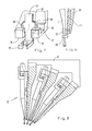
- a first bending transducer unit 3 has an angular segment 4, which is connected to the carrier 2 via a connecting piece 5 is.
- the segment carries 16 first piezoelectric ones Bending transducer 6, each at its free end Have laying needle 7.
- a second bending transducer unit 8 also has an angular segment 9 which is attached to the carrier 2 by a screw 10.
- the Segment carries 16 second piezoelectric bending transducers 11, which have an abutment 12 at the free end. Cable bundles 13 and 14 serve the bending transducer units 3 and 8 after installing segments 4 and 9 on Carrier 2 with the associated control devices connect.
- each laying needle 7 shows three jacquard laying bars 101, each have a structure according to FIGS. 3 to 5. With these three laying bars, the laying needles 7 are like this staggered against each other that - if everyone Laying needles 7 are in the middle position - everyone A laying needle is assigned to Nadelgasse.
- These three Laying bars are fixed to the machine frame by a bridge 30 connected, the relative swinging motion through the knitting needles. It is also possible, each laying rail in the longitudinal direction to be offset by an offset control unit. Likewise it is possible to use the ingot package with fixed knitting needles to swing.
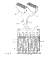
- FIG. 9 there is a bending transducer unit 3 with associated segment 4, which carries a total of 16 first bending transducers 6. These are via a bundle of conductors 31 with a 17-pin connector 32 connected. Behind it is indicated that 16 second Bending transducers 111 are provided which block 120 Taxes. These bending transducers are via bundle 33 connected with a 17-pin connector 34. Hint knitting needles 35 are illustrated, by the Alleys 36 swing the laying needles 7 through. If all Laying needles 7 are in the middle position every fourth alley 36 is covered with a laying needle 7. With four of the same design, but each with a needle pitch staggered laying needles 7 can be achieve that all needle lanes 36 at the same time can be occupied.
- the laying needles 7 also displaced in other ways are considered by piezoelectric bending transducers, for example with push pins or sinkers and return springs.
- the control of the additional stops can be done purely mechanically.
Landscapes
- Engineering & Computer Science (AREA)
- Textile Engineering (AREA)
- Knitting Machines (AREA)
Description
- Fig. 1
- einen Querschnitt durch eine Jacquard-Legebarre bei einer erfindungsgemäßen Kettenwirkmaschine,
- Fig. 2
- eine Vorderansicht der Jacquard-Legebarre der Fig. 1,
- Fig. 3
- eine geänderte Ausführungsform in einem Fig. 1 entsprechenden Querschnitt,
- Fig. 4
- eine Teildarstellung mit der Legenadel in der einen Endstellung,
- Fig. 5
- eine Teildarstellung mit der Legenadel in der anderen Endstellung,
- Fig. 6
- eine weitere Abwandlung in einem Querschnitt ähnlich der Fig. 1,
- Fig. 7
- die Ausführungsform der Fig. 6 in räumlicher Darstellung,
- Fig. 8
- den Legebarrenbereich einer erfindungsgemäßen Kettenwirkmaschine und
- Fig. 9
- eine Draufsicht auf ein Segment mit zugehörigen Biegewandlern.
Claims (16)
- Kettenwirkmaschine mit Wirknadeln, die eine vorgegebene Teilung haben, und mindestens einer Jacquard-Legebarre (1), deren Legenadeln (7) durch Stellglieder einer Nadel-Ansteuerung zwischen zwei Endstellungen hin und her bewegbar sind, die durch in Barrenrichtung feste Endanschläge (13, 14) vorgegeben sind, dadurch gekennzeichnet, daß die Endstellungen einen Abstand gleich der doppelten Nadelteilung haben und daß zusätzliche Anschläge (15, 16; 115, 116) vorgesehen sind, die durch Stellglieder (8) einer Anschlag-Ansteuerung wahlweise wirksam zu machen sind und in ihrer wirksamen Stellung die Legenadeln (7) in einer Mittelstellung halten.
- Kettenwirkmaschine nach Anspruch 1, dadurch gekennzeichnet, daß die Stellglieder (8) der Anschlag-Ansteuerung quer zur Bewegungsebene der Legenadeln (7) verlagerbar sind.
- Kettenwirkmaschine nach Anspruch 1 oder 2, dadurch gekennzeichnet, daß die zusätzlichen Anschläge (15, 16) die Legenadel (7) gabelförmig umgreifen und am Ende eines zweiarmigen Hebels (17) angebracht sind und daß ein Widerlager (12) vom Stellglied wahlweise in die Bahn des anderen Hebelendes (19) einführbar ist.
- Kettenwirkmaschine nach Anspruch 1 oder 2, dadurch gekennzeichnet, daß ein Block (120), der vom Stellglied in eine vordere und eine hintere Stellung verlagerbar ist, im vorderen Teil eine vordere Bahn (121) zwischen dem einen Endanschlag (114) und einem ersten zusätzlichen Anschlag (115), im hinteren Teil eine hintere Bahn (122) zwischen dem anderen Endanschlag (113) und einem zweiten zusätzlichen Anschlag (116) sowie einen von den zusätzlichen Anschlägen (115, 116) begrenzten Übergang (12) zwischen den Bahnen (121, 122) aufweist.
- Kettenwirkmaschine nach einem der Ansprüche 1 bis 4, dadurch gekennzeichnet, daß die Stellglieder der Nadel-Ansteuerung erste piezoelektrische Biegewandler (6) sind, die mit einem Ende barrenfest gehalten sind und am freien Ende einer Legenadel (7) tragen.
- Kettenwirkmaschine nach Anspruch 5, dadurch gekennzeichnet, daß die ersten Biegewandler (6) in eine linke und in eine rechte Auslenkstellung schaltbar sind.
- Kettenwirkmaschine nach einem der Ansprüche 1 bis 6, dadurch gekennzeichnet, daß die Stellglieder der Anschlag-Ansteuerung zweite piezo-elektrische Biegewandler (11; 111) sind, die mit einem Ende barrenfest gehalten sind und mit dem freien Ende auf die zusätzlichen Anschläge (15, 16; 115, 116) einwirken.
- Kettenwirkmaschine nach Anspruch 3 und 7, dadurch gekennzeichnet, daß die zweiten Biegewandler (11) am freien Ende das Widerlager (12) tragen.
- Kettenwirkmaschine nach Anspruch 4 und 7, dadurch gekennzeichnet, daß die zweiten Biegewandler (111) am freien Ende den Block (120) tragen.
- Kettenwirkmaschine nach einem der Ansprüche 7 bis 9, dadurch gekennzeichnet, daß barrenfeste Queranschläge (126, 127) vorgesehen sind, die den Hub der zweiten Biegewandler (111) begrenzen.
- Kettenwirkmaschine nach einem der Ansprüche 7 bis 10, dadurch gekennzeichnet, daß die zweiten Biegewandler (111) in eine vordere und eine hintere Auslenkstellung schaltbar sind.
- Kettenwirkmaschine nach einem der Ansprüche 5 bis 11, dadurch gekennzeichnet, daß die zweiten Biegewandler (11; 111) zwischen dem Träger (2; 102) der Legebarre und den ersten Biegewandlern (6) angeordnet sind.
- Kettenwirkmaschine nach einem der Ansprüche 5 bis 12, dadurch gekennzeichnet, daß zwei Arten von an der Legebarre (1) zu befestigenden Segmenten (4, 9) vorgesehen sind, die eine vorbestimmte Zahl von ersten (6) bzw. zweiten Biegewandlern (11) tragen.
- Kettenwirkmaschine nach Anspruch 13, dadurch gekennzeichnet, daß die Segmente (4, 9) 16 erste bzw. 16 zweite Biegewandler tragen.
- Kettenwirkmaschine nach einem der Ansprüche 1 bis 14, dadurch gekennzeichnet, daß mindestens drei Jacquard-Legebarren (101) vorhanden sind.
- Kettenwirkmaschine nach einem der Ansprüche 1 bis 15, dadurch gekennzeichnet, daß die benachbarten Mittelstellungen einen Abstand gleich der vierfachen Nadelteilung haben.
Applications Claiming Priority (2)
| Application Number | Priority Date | Filing Date | Title |
|---|---|---|---|
| DE19651053 | 1996-12-09 | ||
| DE19651053A DE19651053C1 (de) | 1996-12-09 | 1996-12-09 | Kettenwirkmaschine mit Jacquard-Legebarre |
Publications (2)
| Publication Number | Publication Date |
|---|---|
| EP0846797A1 EP0846797A1 (de) | 1998-06-10 |
| EP0846797B1 true EP0846797B1 (de) | 2001-04-04 |
Family
ID=7814083
Family Applications (1)
| Application Number | Title | Priority Date | Filing Date |
|---|---|---|---|
| EP97120683A Expired - Lifetime EP0846797B1 (de) | 1996-12-09 | 1997-11-26 | Kettenwirkmaschine mit Jacquard-Legebarre |
Country Status (7)
| Country | Link |
|---|---|
| US (1) | US5918485A (de) |
| EP (1) | EP0846797B1 (de) |
| JP (1) | JP2930567B2 (de) |
| KR (1) | KR100255223B1 (de) |
| CN (1) | CN1153860C (de) |
| DE (2) | DE19651053C1 (de) |
| ES (1) | ES2156329T3 (de) |
Families Citing this family (15)
| Publication number | Priority date | Publication date | Assignee | Title |
|---|---|---|---|---|
| DE19739540C1 (de) * | 1997-09-09 | 1999-03-04 | Mayer Textilmaschf | Verfahren und Vorrichtung zur Herstellung einer gemusterten Wirkware |
| DE19740200C1 (de) * | 1997-09-12 | 1999-04-01 | Mayer Textilmaschf | Kettenwirkmaschine mit Legeschienen |
| DE19801601C1 (de) * | 1998-01-17 | 1999-03-25 | Mayer Textilmaschf | Kettenwirkmaschine, Verfahren zur Herstellung einer gemusterten Kettenwirkware und gemusterte Kettenwirkware |
| DE19821845C2 (de) | 1998-05-15 | 2000-05-04 | Mayer Textilmaschf | Vorrichtung an Kettenwirkmaschinen zum Positionieren eines Fadenführers |
| DE10066042B4 (de) * | 2000-08-23 | 2004-12-02 | Karl Mayer Textilmaschinenfabrik Gmbh | Kettenwirkmaschine mit mehreren Musterlegebarren |
| IT1391728B1 (it) * | 2008-11-26 | 2012-01-27 | Santoni & C Spa | Attuatore piezoelettrico per barre guidafilo jacquard di macchine tessili |
| IT1391730B1 (it) * | 2008-11-26 | 2012-01-27 | Santoni & C Spa | Dispositivo di connessione per attuatori piezoelettrici di barre jacquard di macchine tessili |
| IT1391729B1 (it) * | 2008-11-26 | 2012-01-27 | Santoni & C Spa | Barra guidafilo jacquard per macchine tessili per maglieria in catena |
| EP2428602B1 (de) * | 2010-09-10 | 2015-08-26 | Karl Mayer Textilmaschinenfabrik GmbH | Legenadelanordnung für eine Jacquard-Legebarre und Jacquard-Legebarre |
| CN102108600B (zh) * | 2011-03-21 | 2012-05-02 | 孙嘉良 | 经编机贾卡针块 |
| DE102014108987B3 (de) | 2014-06-26 | 2015-10-22 | Karl Mayer Textilmaschinenfabrik Gmbh | Wirkware, Verfahren zum Erzeugen einer Wirkware und Kettenwirkmaschine |
| CN107557987B (zh) * | 2017-09-27 | 2022-11-15 | 福建佶龙机械科技股份有限公司 | 一种经编机成圈元件热变形控制装置 |
| CN108978022B (zh) * | 2018-09-17 | 2019-11-15 | 武汉纺织大学 | 一种多挡位贾卡导纱针系统 |
| CN109881355B (zh) * | 2019-03-28 | 2024-04-19 | 江苏明朗星新能源科技发展有限公司 | 大针距贾卡 |
| CN111172667B (zh) * | 2020-01-16 | 2022-06-14 | 广东天海花边有限公司 | 双衬纬贾卡提花多梳经编织物及其编织方法 |
Family Cites Families (13)
| Publication number | Priority date | Publication date | Assignee | Title |
|---|---|---|---|---|
| DE299384C (de) * | ||||
| DE2707015A1 (de) * | 1977-02-18 | 1978-08-24 | Mayer Fa Karl | Kettenwirkmaschine mit jacquardkopf |
| IT1153279B (it) * | 1982-10-21 | 1987-01-14 | Comez Spa | Macchina tessile perfezionata per la formazione di tessuti di vari colori e disegni |
| DE3321733C2 (de) * | 1983-06-16 | 1985-06-20 | Karl Mayer Textil-Maschinen-Fabrik Gmbh, 6053 Obertshausen | Kettenwirkmaschine mit Jacquard-Lochnadeln |
| EP0157813A1 (de) * | 1983-10-05 | 1985-10-16 | Textilma AG | Vorrichtung zum antrieb und gesteuerten vorschub-hub von schuss-stangen längs des nadelbetts auf wirk-, häkelgalon- und ähnlichen maschinen. |
| DD299384A7 (de) * | 1989-10-20 | 1992-04-16 | Chemnitzer Webmaschinenbau Gmbh,De | Vorrichtung zur elektromagnetischen mustersteuerung an textilmaschinen, insbesondere doppelteppichwebmaschinen |
| DE4028390C2 (de) * | 1990-09-07 | 1994-06-09 | Mayer Textilmaschf | Elektromagnetisch arbeitende Jacquard-Steuervorrichtung |
| DE4226899C1 (de) * | 1992-08-14 | 1994-01-13 | Mayer Textilmaschf | Kettenwirkmaschine mit Jacquard-Steuerung |
| DE4337265C1 (de) * | 1993-11-02 | 1995-03-09 | Mayer Textilmaschf | Kettenwirkmaschine mit mindestens einer Legebarre |
| DE4414876C2 (de) * | 1994-04-28 | 1996-05-30 | Mayer Textilmaschf | Verfahren zum Herstellen einer Kettenwirkware, Kettenwirkmaschine zur Durchführung dieses Verfahrens und Kettenwirkware |
| DE4418714C1 (de) * | 1994-05-28 | 1995-06-22 | Mayer Textilmaschf | Kettenwirkmaschine mit wenigstens einer Legebarre und Austauschelement für eine solche Kettenwirkmaschine |
| DE4442555C2 (de) * | 1994-11-30 | 1997-03-13 | Mayer Textilmaschf | Kettenwirkmaschine |
| DE4444823C2 (de) * | 1994-12-15 | 1998-01-08 | Liba Maschf | Kettenwirkmaschine mit auf einer Legebarre angebrachten individuell bewegbaren Fadenführern |
-
1996
- 1996-12-09 DE DE19651053A patent/DE19651053C1/de not_active Expired - Fee Related
-
1997
- 1997-11-26 EP EP97120683A patent/EP0846797B1/de not_active Expired - Lifetime
- 1997-11-26 ES ES97120683T patent/ES2156329T3/es not_active Expired - Lifetime
- 1997-11-26 DE DE59703288T patent/DE59703288D1/de not_active Expired - Fee Related
- 1997-12-05 JP JP9335887A patent/JP2930567B2/ja not_active Expired - Lifetime
- 1997-12-05 US US08/985,689 patent/US5918485A/en not_active Expired - Fee Related
- 1997-12-06 KR KR1019970066466A patent/KR100255223B1/ko not_active Expired - Fee Related
- 1997-12-09 CN CNB971261156A patent/CN1153860C/zh not_active Expired - Fee Related
Also Published As
| Publication number | Publication date |
|---|---|
| EP0846797A1 (de) | 1998-06-10 |
| ES2156329T3 (es) | 2001-06-16 |
| KR100255223B1 (ko) | 2000-05-01 |
| CN1153860C (zh) | 2004-06-16 |
| JPH10168720A (ja) | 1998-06-23 |
| DE19651053C1 (de) | 1998-06-10 |
| KR19980063868A (ko) | 1998-10-07 |
| JP2930567B2 (ja) | 1999-08-03 |
| DE59703288D1 (de) | 2001-05-10 |
| CN1189549A (zh) | 1998-08-05 |
| US5918485A (en) | 1999-07-06 |
Similar Documents
| Publication | Publication Date | Title |
|---|---|---|
| EP0846797B1 (de) | Kettenwirkmaschine mit Jacquard-Legebarre | |
| DE2910532A1 (de) | Flachstrickmaschine zur herstellung gemusterter strickwaren | |
| DE3050591C2 (de) | Flachstrickmaschine mit einstelbarer Maschendichte | |
| DE3321733A1 (de) | Kettenwirkmaschine mit jacquard-lochnadeln | |
| CH659835A5 (de) | Flachstrickmaschine mit nadelauswahleinrichtung. | |
| DE4421388A1 (de) | Nadelbefestigungsvorrichtung für Wirkmaschinen | |
| DE2323688A1 (de) | Strickmaschine | |
| DE68909692T2 (de) | Frontgangschaltung für ein Fahrrad. | |
| DE2409421C2 (de) | Vorrichtung zur mechanischen Betätigung von Fadenführungsgliedern | |
| EP1475469B1 (de) | Strickmaschine, insbesondere Rundstrickmaschine, und dafür geeignete Steuerplatine | |
| DE4017357C1 (en) | Jacquard guide bar for use with thicker yarns - comprises guide needles, shifted by displacement components according to a pattern, mounted on a support | |
| CH651081A5 (de) | Stickmaschine. | |
| DE102004051694A1 (de) | Verriegelungsmechanismus für Kraftfahrzeugsitzschienen | |
| DE1585228A1 (de) | Rundstrickmaschine mit elektromagnetisch-mechanischer Steuerung der Stricknadeln | |
| CH666064A5 (de) | Flachstrickmaschine mit elektromechanischer auswahl. | |
| EP0810138B1 (de) | Verschlussvorrichtung für Eisenbahnweichen | |
| EP1088923A2 (de) | Kettenwirkmaschine mit Musterpresse | |
| DE2926928C2 (de) | "Mustergetriebe für Kettenwirkmaschinen o.dgl. | |
| EP0814996A1 (de) | Weichenantrieb | |
| DE68902843T2 (de) | Nadelauswahlvorrichtung fuer eine strickmaschine. | |
| DE2735492A1 (de) | Auswahl- und steuervorrichtung fuer die nadeln von rundstrickmaschinen | |
| DE2438756C2 (de) | Gleisweiche, insbesondere Schnellfahrweiche | |
| DE102010032996A1 (de) | Legebarrenanordnung einer Kettenwirkmaschine | |
| DE2320789A1 (de) | Schiebernadel fuer rundstrickmaschinen | |
| EP0911437B1 (de) | Stickmaschine, insbesondere Schifflistickmaschine, mit beweglichem Fadenleiter |
Legal Events
| Date | Code | Title | Description |
|---|---|---|---|
| PUAI | Public reference made under article 153(3) epc to a published international application that has entered the european phase |
Free format text: ORIGINAL CODE: 0009012 |
|
| 17P | Request for examination filed |
Effective date: 19980415 |
|
| AK | Designated contracting states |
Kind code of ref document: A1 Designated state(s): CH DE ES FR GB IT LI |
|
| AX | Request for extension of the european patent |
Free format text: AL;LT;LV;MK;RO;SI |
|
| AKX | Designation fees paid |
Free format text: CH DE ES FR GB IT LI |
|
| RBV | Designated contracting states (corrected) |
Designated state(s): CH DE ES FR GB IT LI |
|
| GRAG | Despatch of communication of intention to grant |
Free format text: ORIGINAL CODE: EPIDOS AGRA |
|
| GRAG | Despatch of communication of intention to grant |
Free format text: ORIGINAL CODE: EPIDOS AGRA |
|
| GRAH | Despatch of communication of intention to grant a patent |
Free format text: ORIGINAL CODE: EPIDOS IGRA |
|
| 17Q | First examination report despatched |
Effective date: 20000816 |
|
| GRAH | Despatch of communication of intention to grant a patent |
Free format text: ORIGINAL CODE: EPIDOS IGRA |
|
| GRAA | (expected) grant |
Free format text: ORIGINAL CODE: 0009210 |
|
| AK | Designated contracting states |
Kind code of ref document: B1 Designated state(s): CH DE ES FR GB IT LI |
|
| ITF | It: translation for a ep patent filed | ||
| REG | Reference to a national code |
Ref country code: CH Ref legal event code: NV Representative=s name: BOVARD AG PATENTANWAELTE Ref country code: CH Ref legal event code: EP |
|
| GBT | Gb: translation of ep patent filed (gb section 77(6)(a)/1977) |
Effective date: 20010404 |
|
| REF | Corresponds to: |
Ref document number: 59703288 Country of ref document: DE Date of ref document: 20010510 |
|
| REG | Reference to a national code |
Ref country code: ES Ref legal event code: FG2A Ref document number: 2156329 Country of ref document: ES Kind code of ref document: T3 |
|
| ET | Fr: translation filed | ||
| PG25 | Lapsed in a contracting state [announced via postgrant information from national office to epo] |
Ref country code: GB Free format text: LAPSE BECAUSE OF NON-PAYMENT OF DUE FEES Effective date: 20011126 |
|
| PG25 | Lapsed in a contracting state [announced via postgrant information from national office to epo] |
Ref country code: ES Free format text: LAPSE BECAUSE OF NON-PAYMENT OF DUE FEES Effective date: 20011127 |
|
| REG | Reference to a national code |
Ref country code: GB Ref legal event code: IF02 |
|
| PLBE | No opposition filed within time limit |
Free format text: ORIGINAL CODE: 0009261 |
|
| STAA | Information on the status of an ep patent application or granted ep patent |
Free format text: STATUS: NO OPPOSITION FILED WITHIN TIME LIMIT |
|
| 26N | No opposition filed | ||
| GBPC | Gb: european patent ceased through non-payment of renewal fee |
Effective date: 20011126 |
|
| PG25 | Lapsed in a contracting state [announced via postgrant information from national office to epo] |
Ref country code: FR Free format text: LAPSE BECAUSE OF NON-PAYMENT OF DUE FEES Effective date: 20020730 |
|
| REG | Reference to a national code |
Ref country code: FR Ref legal event code: ST |
|
| REG | Reference to a national code |
Ref country code: FR Ref legal event code: ST |
|
| REG | Reference to a national code |
Ref country code: ES Ref legal event code: FD2A Effective date: 20021213 |
|
| PG25 | Lapsed in a contracting state [announced via postgrant information from national office to epo] |
Ref country code: IT Free format text: LAPSE BECAUSE OF NON-PAYMENT OF DUE FEES;WARNING: LAPSES OF ITALIAN PATENTS WITH EFFECTIVE DATE BEFORE 2007 MAY HAVE OCCURRED AT ANY TIME BEFORE 2007. THE CORRECT EFFECTIVE DATE MAY BE DIFFERENT FROM THE ONE RECORDED. Effective date: 20051126 |
|
| PGFP | Annual fee paid to national office [announced via postgrant information from national office to epo] |
Ref country code: DE Payment date: 20071116 Year of fee payment: 11 |
|
| PGFP | Annual fee paid to national office [announced via postgrant information from national office to epo] |
Ref country code: CH Payment date: 20071126 Year of fee payment: 11 |
|
| REG | Reference to a national code |
Ref country code: CH Ref legal event code: PL |
|
| PG25 | Lapsed in a contracting state [announced via postgrant information from national office to epo] |
Ref country code: LI Free format text: LAPSE BECAUSE OF NON-PAYMENT OF DUE FEES Effective date: 20081130 Ref country code: DE Free format text: LAPSE BECAUSE OF NON-PAYMENT OF DUE FEES Effective date: 20090603 Ref country code: CH Free format text: LAPSE BECAUSE OF NON-PAYMENT OF DUE FEES Effective date: 20081130 |