EP0845854B1 - Fühler für mechanische vibrationen und vibrations-dämpfungs-regler - Google Patents
Fühler für mechanische vibrationen und vibrations-dämpfungs-regler Download PDFInfo
- Publication number
- EP0845854B1 EP0845854B1 EP96926637A EP96926637A EP0845854B1 EP 0845854 B1 EP0845854 B1 EP 0845854B1 EP 96926637 A EP96926637 A EP 96926637A EP 96926637 A EP96926637 A EP 96926637A EP 0845854 B1 EP0845854 B1 EP 0845854B1
- Authority
- EP
- European Patent Office
- Prior art keywords
- mechanical
- motor
- signal
- control apparatus
- equivalent
- Prior art date
- Legal status (The legal status is an assumption and is not a legal conclusion. Google has not performed a legal analysis and makes no representation as to the accuracy of the status listed.)
- Expired - Lifetime
Links
Images


Classifications
-
- G—PHYSICS
- G01—MEASURING; TESTING
- G01H—MEASUREMENT OF MECHANICAL VIBRATIONS OR ULTRASONIC, SONIC OR INFRASONIC WAVES
- G01H1/00—Measuring characteristics of vibrations in solids by using direct conduction to the detector
- G01H1/003—Measuring characteristics of vibrations in solids by using direct conduction to the detector of rotating machines
-
- G—PHYSICS
- G05—CONTROLLING; REGULATING
- G05D—SYSTEMS FOR CONTROLLING OR REGULATING NON-ELECTRIC VARIABLES
- G05D19/00—Control of mechanical oscillations, e.g. of amplitude, of frequency, of phase
- G05D19/02—Control of mechanical oscillations, e.g. of amplitude, of frequency, of phase characterised by the use of electric means
-
- H—ELECTRICITY
- H02—GENERATION; CONVERSION OR DISTRIBUTION OF ELECTRIC POWER
- H02P—CONTROL OR REGULATION OF ELECTRIC MOTORS, ELECTRIC GENERATORS OR DYNAMO-ELECTRIC CONVERTERS; CONTROLLING TRANSFORMERS, REACTORS OR CHOKE COILS
- H02P23/00—Arrangements or methods for the control of AC motors characterised by a control method other than vector control
- H02P23/16—Controlling the angular speed of one shaft
Definitions
- the present invention relates to a mechanical-vibration detecting apparatus, a mechanical-vibration reduction control apparatus and a motor control apparatus.
- a quadratic observer is constituted with the angular velocity and step-like torque disturbance of the equivalent rigid body system as state variables, so that not only an equivalent rigid body model and a proportional operation means but also an integrating operation means are required in order to constitute a mechanical-vibration detecting apparatus.
- Two parameters are required to be set for the observer and, furthermore, the phase of a mechanical vibration signal varies largely in accordance with the set-values of the parameters so that there arises a problem that it is difficult to adjust the parameters.
- an object of the present invention is to provide a mechanical-vibration detecting apparatus in which not only adjustment is easy but also mechanical vibration can be taken out with high accuracy, and to provide a vibration-reduction control apparatus by which reduction of mechanical vibration can be achieved.
- said objective is solved by a mechanical-vibration detecting apparatus having the features of independent claim 1.
- said objective is also solved by a mechanical-vibration detecting reduction control apparatus having the features of claim 3.
- said objective is also solved by a mechanical-vibration reduction control apparatus having the feature of claim 4.
- said objective is also solved by a motor control apparatus having the features of claims 6.
- a linear equivalent rigid body observer is constituted so that one integrating means becomes unnecessary and the range of the parameter for stabilizing the system is widened correspondingly. Furthermore, because only one parameter is required for setting the observer and the sensitivity of the parameter is low with respect to the phase of the mechanical vibration signal, it is easy to adjust the parameter.
- a block 102 shows a mechanical- vibration detecting apparatus constituted by an equivalent rigid body model 103, a proportional operation means 104, and a high-pass filter 105.
- the apparatus is supplied with a motor torque signal ⁇ and a motor velocity signal (a motor angular velocity v m is used here) and outputs a mechanical vibration signal.
- a block 101 shows a mechanism (including a motor) having a mechanical resonance system.
- a transmission function of the mechanism system 101 can be separated into an equivalent rigid body system G 1 (s) and a mechanical resonance system G 2 (s) as follows:
- G 1 ( s ) ⁇ s + D 0
- G 2 ( s ) ⁇ 2 r ⁇ 2 a s 2 + ⁇ a Q a s + ⁇ 2 a s 2 + ⁇ r Q r s + ⁇ 2 r in which y is the reciprocal of a moment of inertia of the equivalent rigid body system, D 0 / ⁇ is the viscous friction coefficient of the equivalent rigid body system, and ⁇ r and ⁇ a are the resonance frequency and antiresonance frequency of the mechanical resonance system.
- the block 101 surrounded by a broken line shows an mechanism (including electric motor) with a mechanical resonance phenomenon
- the block 102 surrounded by a one-dotted chain line shows a mechanical-vibration detecting apparatus according to the present teaching.
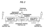
- the mechanism assume a 2-inertia torsional resonance system shown in Fig.. 2.
- Equations of motion in the mechanical system in the drawing are given as follows: in which ⁇ m angle of the motor axis [rad] ⁇ L angle of the load axis [rad] ⁇ torsional angle of the equivalent linear spring [rad] J m moment of inertia on the motor axis side [Kgm 2 ] J L moment of inertia on the load axis side [Kgm 2 ] K spring constant of the equivalent linear spring [Nm/rad] D m viscous friction coefficient of the motor axis [Nm/(rad/s)] D L viscous friction coefficient of the load axis [Nm/(rad/s)] D T equivalent viscous friction coefficient of the equivalent linear spring system [Nm/(rad/s)] u 1 torque generated on the motor axis [Nm]
- the 2-inertia resonance system can be separated into the equivalent rigid body system G 1 (s) shown in the block 101 surrounded by the broken line in Fig. 1 and the mechanical resonance system G 2 (s) as follows:
- G 1 ( s ) 1 J m ⁇ 2 a ⁇ 2 r 1 s + D 0
- G 2 ( s ) ⁇ 2 r s 2 + ⁇ r Q r s + ⁇ 2 r s 2 + ⁇ a Q a s + ⁇ 2 a ⁇ 2 a
- the mechanical vibration component can be detected selectively on the basis of a difference signal which expresses a value obtained by subtracting the detected velocity of the equivalent rigid body system from the observation output.
- e ( t ) v m ( t )- v ( t )
- FIG. 3 shows the case where the present invention is applied to a motor torque control apparatus.
- the motor-containing mechanism system 101 and the mechanical- vibration detecting apparatus 102 are the same as those in the first embodiment.
- the reference numeral 106 designates a motor drive device which is supplied with a torque command and which outputs torque generated by the motor.
- the motor drive device 106 is constituted by a power amplifier, and so on.
- As a motor torque signal ⁇ to be supplied to the mechanical-vibration detecting apparatus 102 a generated torque monitor signal or a torque command signal is used.
- the mechanical vibration signal estimated by the mechanical-vibration detecting apparatus 102 is supplied to the phase adjuster 107.
- the output of the phase adjuster 107 is supplied to the amplitude adjuster 108, so that a signal obtained by addition of the output w of the amplitude adjuster 108 to the torque command is supplied, as a new torque command, to the motor torque control apparatus.
- the phase adjuster 107 and the amplitude adjuster 108 adjust the phase and amplitude of the mechanical vibration signal which is an output of the mechanical-vibration detecting apparatus 102 so as to suppress the vibration of the control system containing the motor and the mechanical resonance system. Because the mechanical vibration signal output from the mechanical-vibration detecting apparatus 102 is advanced in phase than the vibration of motor angular velocity v m and the degree of the phase advance is adjusted on the basis of the gain k of the proportional operation means 104, the phase adjuster 107 may be constituted by a phase delay element such as a low-pass filter, or the like.
- the amplitude adjuster 108 may be constituted by an amplifier or an arithmetic unit for multiplying the output signal of the phase adjuster 107 by the gain.
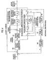
- FIG. 4 shows the case where the present teaching is applied to a motor velocity control. apparatus.
- the motor-containing mechanism system 101 and the mechanical vibration detecting apparatus 102 are the same as those in the first embodiment, and the motor drive device 106, the phase adjuster 107 and the amplitude adjuster 108 have the same functions as those in the second embodiment, except that the output w of the amplitude adjuster 108 is added to a velocity command so that the added-up signal is supplied, as a new velocity command, to the motor velocity control apparatus.
- the reference numeral 109 designates a velocity control compensator which is supplied with a difference signal between the velocity command and a velocity feedback signal, and which outputs a torque instruction.
- a value obtained by addition of torque disturbance d to the torque instruction may be supplied, as a new torque signal, to the mechanical-vibration detecting apparatus 102 if the detected or estimated value of the torque disturbance d is obtained.
- the high-pass filter 105 becomes unnecessary.
- the torque instruction is determined on the basis of proportional integrating control in the velocity control compensator 109 in the third embodiment, a value obtained by inversion of the positive/negative sign of the resulting value of the integrating operation may be used as the estimated torque disturbance value.
- the present teaching can be applied to various motor-driven industrial machines such as machine tools, robots, semiconductor producing apparatuses, metallurgical apparatuses, and other general industrial machines, and office machines.
Landscapes
- Engineering & Computer Science (AREA)
- Physics & Mathematics (AREA)
- General Physics & Mathematics (AREA)
- Power Engineering (AREA)
- Automation & Control Theory (AREA)
- Control Of Electric Motors In General (AREA)
Claims (6)
- Erfassungsvorrichtung für mechanische Schwingungen (102), angewandt an einer Motorsteuerungsvorrichtung zum Steuern des Drehmomentes eines Motors, dadurch gekennzeichnet, dass die Erfassungsvorrichtung aufweist ein äquivalentes Starrkörpermodel (103) des Motors, das die Übertragungscharakteristik von G1 = y / (s + D0) hat, wo γ der Kehrwert des Trägheitsmomentes eines äquivalenten Starrkörpersystems ist, und D0/γ der viskose Reibungskoeffizient des äquivalenten Starrkörpersystems ist; eine Proportional- Betriebseinrichtung (104); einen Hochpassfilter (105); und
eine Einrichtung zum Addieren eines Drehmomentsignales (τ, τr) der Motorsteuerungsvorrichtung und eines Ausgangssignales der Proportional- Betriebseinrichtung (104), um ein resultierendes zusätzliches Signal zu dem äquivalenten Starrkörpermodels (103) zuzuführen, und zum Subtrahieren eines Ausgangssignales des äquivalenten Starrkörpermodels (103) von einem Geschwindigkeitssignal (Vm) der Motorsteuervorrichtung, um ein resultierendes Differenzsignal zu dem Hochpassfilter (105) zuzuführen, so dass ein Ausgangssignal des Hochpassfilters (105) als ein mechanisches Schwingungssignal verwendet wird; und eine Einrichtung zum Zuführen des Differenzsignales zu der Proportional- Betriebseinrichtung (104). - Erfassungsvorrichtung für mechanische Schwingungen nach Anspruch 1, wobei der Motor mit einer Last durch eine äquivalente lineare Feder verbunden ist, K eine Konstante der äquivalenten linearen Feder ist, Jm ein Trägheitsmoment des Motors ist, JI ein Trägheitsmoment der Last ist, Dm ein viskoser Reibungskoeffizient des Motors ist, DL ein viskoser Reibungskoeffizient der Last ist, und DT ein äquivalenter viskoser Reibungskoeffizient der äquivalenten linearen Feder ist (wo y = ωa2/(Jmωr2), ωa2 = K/JL, ωr2 = {(1 + a) K/ (aJM)} [(1 + (DmDT + DLDT + DmDL) / {(1 + a)JmK}], a = JL/Jm, D0 = [( Dm + DL) / {(1 + a)Jm}] · (1/[1 + (DmDT + DLDT +DmDL) / {(1 + a) JmK}], wobei s der Laplace- Operator ist).
- Steuervorrichtung zur Reduzierung mechanischer Schwingung, die aufweist:eine Erfassungsvorrichtung für mechanische Schwingungen nach Anspruch 1 undaußerdem aufweisteinen Phaseneinsteller (107);einen Amplitudeneinsteller (108), wobeidas Ausgangssignal des Hochpassfilters (105) zu dem Phaseneinsteller (107) zugeführt wird, und ein Ausgangssignal des Phaseneinstellers (107) zu dem Amplitudeneinsteller (108) zugeführt wird, so dass ein Signal, erhalten durch Addieren eines Ausgangssignales (w) des Amplitudeneinstellers (108) zu einem Drehmomentbefehl (τr), gegeben zu der Motorsteuervorrichtung, als ein neuer Drehmomentbefehl verwendet wird.
- Steuervorrichtung für die Reduzierung mechanischer Schwingungen, die aufweist eine Erfassungsvorrichtung für mechanische Schwingungen nach Anspruch 1 und die außerdem aufweist:wobei ein Ausgangssignal des Hochpassfilters (105) zu dem Phaseneinsteller (107) zugeführt wird, und ein Ausgangssignal des Phaseneinstellers (107) zu dem Amplitudeneinsteller (108) zugeführt wird, so dass ein Signal, erhalten durch Addieren eines Ausgangssignales (w) des Amplitudeneinstellers (108) zu einem Geschwindigkeitsbefehl (Vr), gegeben zu der Motorsteuervorrichtung, als ein neuer Geschwindigkeitsbefehl verwendet wird.einen Phaseneinsteller (107);einen Amplitudeneinsteller (108); undeine Einrichtung zum Zuführen des Differenzsignales zu der Proportional- Betriebseinrichtung (104);einen Geschwindigkeits- Steuerkompensator (109), dem ein Differenzsignal zwischen dem Geschwindigkeitsbefehl und dem Geschwindigkeits- Rückkopplungssignal zugeführt wird, und der eine Drehmomentinstruktion ausgibt,
- Steuervorrichtung für die Reduzierung mechanischer Schwingungen nach Anspruch 4, wobei der Motor mit einer Last durch eine äquivalente, lineare Feder verbunden ist, K eine Konstante der äquivalenten, linearen Feder ist, Jm eine Trägheitsmoment des Motors ist, JL ein Trägheitsmoment der Last ist, Dm ein viskoser Reibungskoeffizient des Motors ist, DL ein viskoser Reibungskoeffizient der Last ist und DT ein äquivalenter viskoser Reibungskoeffizient der äquivalenten, linearen Feder ist (wo γ = ωa2 /(Jmωr2), ωa2 = K/JL, ωr2 = {(1 + a) K/ (aJM)} [(1 + (DmDT + DLDT + DmDL) / {(1 + a)JmK}], a = JL/Jm, D0 = [( Dm + DL) / {(1 + a)Jm}] · (1/[1 + (DmDT + DLDT +DmDL) / {(1 + a) JmK}], wobei s der Laplace-Operator ist).
- Motorsteuerungsvorrichtung mit einer Erfassungsvorrichtung für mechanische Schwingungen oder einer Reduzierungsvorrichtung für mechanische Schwingungen nach zumindest einem der Ansprüche 1 bis 5, wobei die Motorsteuerungsvorrichtung außerdem eine Einrichtung aufweist, um ein Drehmoment- Störungssignal (d) durch Erfassen oder Abschätzen zu erhalten, und eine Einrichtung, um das Drehmoment- Störungssignal (d) zu dem Drehmomentsignal (τ) zu addieren, um dadurch ein resultierendes Signal als ein neues Drehmomentsignal zu verwenden.
Applications Claiming Priority (4)
| Application Number | Priority Date | Filing Date | Title |
|---|---|---|---|
| JP23352895A JP3189865B2 (ja) | 1995-08-18 | 1995-08-18 | 機械振動検出装置および制振制御装置 |
| JP23352895 | 1995-08-18 | ||
| JP233528/95 | 1995-08-18 | ||
| PCT/JP1996/002289 WO1997007590A1 (fr) | 1995-08-18 | 1996-08-13 | Dispositif pour detecter des vibrations mecaniques et commande de l'amortissement des vibrations |
Publications (3)
| Publication Number | Publication Date |
|---|---|
| EP0845854A1 EP0845854A1 (de) | 1998-06-03 |
| EP0845854A4 EP0845854A4 (de) | 1998-10-28 |
| EP0845854B1 true EP0845854B1 (de) | 2005-03-23 |
Family
ID=16956461
Family Applications (1)
| Application Number | Title | Priority Date | Filing Date |
|---|---|---|---|
| EP96926637A Expired - Lifetime EP0845854B1 (de) | 1995-08-18 | 1996-08-13 | Fühler für mechanische vibrationen und vibrations-dämpfungs-regler |
Country Status (7)
| Country | Link |
|---|---|
| US (1) | US5990645A (de) |
| EP (1) | EP0845854B1 (de) |
| JP (1) | JP3189865B2 (de) |
| KR (1) | KR100425819B1 (de) |
| CN (1) | CN1071065C (de) |
| DE (1) | DE69634513T2 (de) |
| WO (1) | WO1997007590A1 (de) |
Families Citing this family (30)
| Publication number | Priority date | Publication date | Assignee | Title |
|---|---|---|---|---|
| US6032552A (en) | 1995-08-07 | 2000-03-07 | Quality Research Development & Consulting, Inc. | Vibration control by confinement of vibration energy |
| US20060106500A1 (en) * | 1995-08-07 | 2006-05-18 | Quality Research, Development & Consulting, Inc. | Vibration control by confinement of vibration energy |
| JP3900219B2 (ja) | 1997-10-24 | 2007-04-04 | 株式会社安川電機 | 電動機速度制御装置および同装置のゲイン設定方法 |
| CN1146765C (zh) * | 1998-09-28 | 2004-04-21 | 株式会社安川电机 | 位置控制装置 |
| JP2002171778A (ja) * | 2000-09-25 | 2002-06-14 | Aisin Seiki Co Ltd | 電動モータの振動抑制制御装置及び電動モータの振動抑制制御における設計手法 |
| JP4660941B2 (ja) * | 2001-02-23 | 2011-03-30 | アイシン精機株式会社 | 電動モータの制御装置 |
| JP3508742B2 (ja) * | 2001-06-18 | 2004-03-22 | 日産自動車株式会社 | 電動モータを用いた車両の制振制御装置 |
| US6936990B2 (en) * | 2002-03-29 | 2005-08-30 | Matsushita Electric Industrial Co., Ltd. | Method for controlling electric motor and apparatus for controlling the same |
| JP4075803B2 (ja) * | 2002-04-05 | 2008-04-16 | 三菱電機株式会社 | モータの制御装置 |
| US6789641B2 (en) | 2002-08-14 | 2004-09-14 | Trw Inc. | Method and apparatus for controlling an electric assist motor using a modified blending filter |
| JP3678276B2 (ja) * | 2002-08-22 | 2005-08-03 | 株式会社安川電機 | フルクローズド制御装置 |
| EP1501186B1 (de) * | 2003-07-18 | 2018-08-22 | III Holdings 10, LLC | Steuergerät für einen Motor |
| US7027897B2 (en) * | 2004-01-27 | 2006-04-11 | Bombardier Transportation Gmbh | Apparatus and method for suppressing mechanical resonance in a mass transit vehicle |
| US7109679B2 (en) | 2004-03-09 | 2006-09-19 | Hr Textron, Inc. | Damping for electromechanical actuators |
| JP2008048545A (ja) * | 2006-08-17 | 2008-02-28 | Yaskawa Electric Corp | 位置制御装置と位置制御方法 |
| JP2009118684A (ja) * | 2007-11-08 | 2009-05-28 | Mitsubishi Electric Corp | 振動抑制制御装置 |
| JP5645564B2 (ja) * | 2010-09-14 | 2014-12-24 | キヤノン株式会社 | センサ装置及びロボット装置 |
| JP5209810B1 (ja) * | 2011-07-27 | 2013-06-12 | ファナック株式会社 | イナーシャと摩擦係数とばね定数を同時に推定する機能を備える電動機の制御装置 |
| JP5899695B2 (ja) * | 2011-08-05 | 2016-04-06 | 日産自動車株式会社 | トルク制御装置 |
| KR101448746B1 (ko) * | 2012-10-17 | 2014-10-10 | 현대자동차 주식회사 | 전기자동차의 안티 저크 제어 방법 및 시스템 |
| US8981702B2 (en) * | 2013-03-15 | 2015-03-17 | Texas Instruments Incorporated | Automated motor control |
| JP6119872B2 (ja) | 2013-10-28 | 2017-04-26 | 株式会社安川電機 | モータ制御装置 |
| JP6325924B2 (ja) * | 2014-07-04 | 2018-05-16 | 株式会社日立製作所 | エレベーター制御装置 |
| CN105375850B (zh) * | 2015-12-24 | 2017-11-28 | 南京埃斯顿自动控制技术有限公司 | 一种电机振动抑制的控制方法 |
| JP6226021B2 (ja) * | 2016-04-28 | 2017-11-08 | 株式会社明電舎 | 試験システムのダイナモメータ制御装置 |
| US11499537B2 (en) * | 2017-12-17 | 2022-11-15 | Microchip Technology Incorporated | Closed loop torque compensation for compressor applications |
| JP7348526B2 (ja) * | 2020-03-02 | 2023-09-21 | シンフォニアテクノロジー株式会社 | 共振抑制制御装置 |
| JP7566669B2 (ja) * | 2021-03-04 | 2024-10-15 | 東洋電機製造株式会社 | 制御装置 |
| US11831215B2 (en) * | 2021-05-06 | 2023-11-28 | Aac Microtech (Changzhou) Co., Ltd. | Linear vibration motor |
| CN114227675A (zh) * | 2021-12-15 | 2022-03-25 | 珠海格力电器股份有限公司 | 一种机器人控制方法、装置、伺服系统和机器人及设备 |
Family Cites Families (12)
| Publication number | Priority date | Publication date | Assignee | Title |
|---|---|---|---|---|
| DE3017327A1 (de) * | 1980-05-06 | 1981-11-12 | Nippon Seiko K.K., Tokyo | Einrichtung zur analyse von harmonischen schwingungen |
| JP2623532B2 (ja) * | 1986-05-27 | 1997-06-25 | 株式会社安川電機 | 防振制御方法 |
| JPH01133587A (ja) * | 1987-11-18 | 1989-05-25 | Kawasaki Steel Corp | 軸振動抑制方法 |
| JP2569152B2 (ja) * | 1988-10-17 | 1997-01-08 | ファナック株式会社 | サーボ制御方法 |
| EP0523255B1 (de) * | 1991-02-05 | 1996-06-05 | Kabushiki Kaisha Yaskawa Denki | Verfahren zur unterdrückung von torsionsschwingungen in einer motorgeschwindigkeitsregelung und vorrichtung dafür |
| DE4141897A1 (de) * | 1991-12-18 | 1993-06-24 | Siemens Ag | Verfahren zur verringerung von schwingungen bei laststoessen bei antrieben mit schwingungsfaehiger mechanischer anordnung |
| JPH06318115A (ja) * | 1993-05-07 | 1994-11-15 | Hitachi Ltd | 位置決め制御方法 |
| JP3337826B2 (ja) * | 1994-06-08 | 2002-10-28 | 株式会社ハーモニック・ドライブ・システムズ | オープンループ振動抑制方法 |
| JP3360935B2 (ja) * | 1994-06-09 | 2003-01-07 | 株式会社安川電機 | 電動機制御系における機械共振検出装置及び制振制御装置 |
| US5831401A (en) * | 1996-03-27 | 1998-11-03 | Bbn Corp | Impedance controller |
| JP3700305B2 (ja) * | 1996-04-19 | 2005-09-28 | 松下電器産業株式会社 | ブラシレスモータの駆動装置とモータのロータ位置検出装置 |
| JPH1133587A (ja) * | 1997-07-18 | 1999-02-09 | Mitsubishi Materials Corp | 重金属含有廃水の処理方法 |
-
1995
- 1995-08-18 JP JP23352895A patent/JP3189865B2/ja not_active Expired - Fee Related
-
1996
- 1996-08-13 DE DE69634513T patent/DE69634513T2/de not_active Expired - Lifetime
- 1996-08-13 WO PCT/JP1996/002289 patent/WO1997007590A1/ja not_active Ceased
- 1996-08-13 CN CN96197475A patent/CN1071065C/zh not_active Expired - Lifetime
- 1996-08-13 KR KR10-1998-0701180A patent/KR100425819B1/ko not_active Expired - Lifetime
- 1996-08-13 EP EP96926637A patent/EP0845854B1/de not_active Expired - Lifetime
- 1996-08-13 US US09/011,844 patent/US5990645A/en not_active Expired - Lifetime
Also Published As
| Publication number | Publication date |
|---|---|
| JPH0956183A (ja) | 1997-02-25 |
| EP0845854A1 (de) | 1998-06-03 |
| CN1198854A (zh) | 1998-11-11 |
| DE69634513T2 (de) | 2005-09-29 |
| US5990645A (en) | 1999-11-23 |
| CN1071065C (zh) | 2001-09-12 |
| WO1997007590A1 (fr) | 1997-02-27 |
| EP0845854A4 (de) | 1998-10-28 |
| KR100425819B1 (ko) | 2004-06-26 |
| DE69634513D1 (de) | 2005-04-28 |
| JP3189865B2 (ja) | 2001-07-16 |
| KR19990037701A (ko) | 1999-05-25 |
Similar Documents
| Publication | Publication Date | Title |
|---|---|---|
| EP0845854B1 (de) | Fühler für mechanische vibrationen und vibrations-dämpfungs-regler | |
| DE69930820T2 (de) | Steuersystem für eine elektrische Servolenkung | |
| US5545957A (en) | Motor speed controller for suppressing shaft torsion vibration | |
| US5473539A (en) | Electrically operated power steering apparatus | |
| EP1591857B1 (de) | Gerät zur Dämpfung von Vibrationen | |
| EP0713287B1 (de) | Leistungssystemstabilisierung für einen Generator | |
| DE69838142T2 (de) | Verfahren und geraet zur robotersteuerung | |
| US7190134B2 (en) | Torsional vibration suppressing method and apparatus in electric motor speed control system | |
| JP4166157B2 (ja) | 電動機制御装置 | |
| US20050200327A1 (en) | Motor control device | |
| CA2110208C (en) | Method and system for estimating inertia of 2-mass system during speed control | |
| EP0523255B1 (de) | Verfahren zur unterdrückung von torsionsschwingungen in einer motorgeschwindigkeitsregelung und vorrichtung dafür | |
| JPH10217173A (ja) | ロボットの非干渉化制御装置 | |
| US20200408631A1 (en) | Controller for evaluating inertia and inertia evaluation method | |
| EP0952372A2 (de) | Anpassung an Phasenverschiebung in einem aktiven, schwingungsdämpfendem System | |
| JPH08278821A (ja) | サーボ制御系の制振方法 | |
| JP2737064B2 (ja) | 制御装置 | |
| JPH07337057A (ja) | 電動機制御系における機械共振検出装置及び制振制御装置 | |
| JP3266391B2 (ja) | 制御装置 | |
| JP6958518B2 (ja) | 動力計制御装置 | |
| JPH089672A (ja) | モータの速度制御装置 | |
| JPH0237973B2 (de) | ||
| KR100222953B1 (ko) | 서보시스템의 제어방법 및 제어장치 | |
| JPH117303A (ja) | サーボ系の駆動制御装置 | |
| JP3294056B2 (ja) | 機械系制御システム |
Legal Events
| Date | Code | Title | Description |
|---|---|---|---|
| PUAI | Public reference made under article 153(3) epc to a published international application that has entered the european phase |
Free format text: ORIGINAL CODE: 0009012 |
|
| 17P | Request for examination filed |
Effective date: 19980218 |
|
| AK | Designated contracting states |
Kind code of ref document: A1 Designated state(s): DE GB SE |
|
| A4 | Supplementary search report drawn up and despatched |
Effective date: 19980909 |
|
| AK | Designated contracting states |
Kind code of ref document: A4 Designated state(s): DE GB SE |
|
| 17Q | First examination report despatched |
Effective date: 20000705 |
|
| GRAP | Despatch of communication of intention to grant a patent |
Free format text: ORIGINAL CODE: EPIDOSNIGR1 |
|
| GRAS | Grant fee paid |
Free format text: ORIGINAL CODE: EPIDOSNIGR3 |
|
| GRAA | (expected) grant |
Free format text: ORIGINAL CODE: 0009210 |
|
| AK | Designated contracting states |
Kind code of ref document: B1 Designated state(s): DE GB SE |
|
| REG | Reference to a national code |
Ref country code: GB Ref legal event code: FG4D |
|
| REF | Corresponds to: |
Ref document number: 69634513 Country of ref document: DE Date of ref document: 20050428 Kind code of ref document: P |
|
| PLBE | No opposition filed within time limit |
Free format text: ORIGINAL CODE: 0009261 |
|
| STAA | Information on the status of an ep patent application or granted ep patent |
Free format text: STATUS: NO OPPOSITION FILED WITHIN TIME LIMIT |
|
| 26N | No opposition filed |
Effective date: 20051227 |
|
| PG25 | Lapsed in a contracting state [announced via postgrant information from national office to epo] |
Ref country code: SE Free format text: LAPSE BECAUSE OF FAILURE TO SUBMIT A TRANSLATION OF THE DESCRIPTION OR TO PAY THE FEE WITHIN THE PRESCRIBED TIME-LIMIT Effective date: 20050623 |
|
| PGFP | Annual fee paid to national office [announced via postgrant information from national office to epo] |
Ref country code: GB Payment date: 20080820 Year of fee payment: 13 |
|
| GBPC | Gb: european patent ceased through non-payment of renewal fee |
Effective date: 20090813 |
|
| PG25 | Lapsed in a contracting state [announced via postgrant information from national office to epo] |
Ref country code: GB Free format text: LAPSE BECAUSE OF NON-PAYMENT OF DUE FEES Effective date: 20090813 |
|
| PGFP | Annual fee paid to national office [announced via postgrant information from national office to epo] |
Ref country code: DE Payment date: 20150804 Year of fee payment: 20 |
|
| REG | Reference to a national code |
Ref country code: DE Ref legal event code: R071 Ref document number: 69634513 Country of ref document: DE |