EP0845383B1 - Regulateur pour batterie d'accumulateurs embarquee sur un vehicule - Google Patents
Regulateur pour batterie d'accumulateurs embarquee sur un vehicule Download PDFInfo
- Publication number
- EP0845383B1 EP0845383B1 EP97925305A EP97925305A EP0845383B1 EP 0845383 B1 EP0845383 B1 EP 0845383B1 EP 97925305 A EP97925305 A EP 97925305A EP 97925305 A EP97925305 A EP 97925305A EP 0845383 B1 EP0845383 B1 EP 0845383B1
- Authority
- EP
- European Patent Office
- Prior art keywords
- battery
- charging
- current
- voltage
- unit cells
- Prior art date
- Legal status (The legal status is an assumption and is not a legal conclusion. Google has not performed a legal analysis and makes no representation as to the accuracy of the status listed.)
- Expired - Lifetime
Links
- 238000007599 discharging Methods 0.000 claims abstract description 45
- 238000001514 detection method Methods 0.000 claims description 38
- 238000006243 chemical reaction Methods 0.000 claims description 4
- 230000006866 deterioration Effects 0.000 abstract description 74
- 238000012423 maintenance Methods 0.000 abstract description 14
- 238000007689 inspection Methods 0.000 abstract description 9
- 230000000052 comparative effect Effects 0.000 description 61
- 230000006698 induction Effects 0.000 description 38
- 238000010586 diagram Methods 0.000 description 16
- 238000002485 combustion reaction Methods 0.000 description 12
- 230000005540 biological transmission Effects 0.000 description 8
- 238000005259 measurement Methods 0.000 description 6
- 230000001172 regenerating effect Effects 0.000 description 6
- 238000013459 approach Methods 0.000 description 5
- 230000003247 decreasing effect Effects 0.000 description 4
- 230000002457 bidirectional effect Effects 0.000 description 3
- 230000000694 effects Effects 0.000 description 3
- 238000009434 installation Methods 0.000 description 3
- 230000001133 acceleration Effects 0.000 description 2
- 230000007423 decrease Effects 0.000 description 2
- 230000002950 deficient Effects 0.000 description 2
- 230000005611 electricity Effects 0.000 description 2
- 238000000034 method Methods 0.000 description 2
- 239000000126 substance Substances 0.000 description 2
- 230000015556 catabolic process Effects 0.000 description 1
- 230000002542 deteriorative effect Effects 0.000 description 1
- 230000001747 exhibiting effect Effects 0.000 description 1
- 238000002474 experimental method Methods 0.000 description 1
- 239000000446 fuel Substances 0.000 description 1
- 239000004973 liquid crystal related substance Substances 0.000 description 1
- 238000004519 manufacturing process Methods 0.000 description 1
- 238000012544 monitoring process Methods 0.000 description 1
- 230000001737 promoting effect Effects 0.000 description 1
- 238000012549 training Methods 0.000 description 1
Images


Classifications
-
- B—PERFORMING OPERATIONS; TRANSPORTING
- B60—VEHICLES IN GENERAL
- B60L—PROPULSION OF ELECTRICALLY-PROPELLED VEHICLES; SUPPLYING ELECTRIC POWER FOR AUXILIARY EQUIPMENT OF ELECTRICALLY-PROPELLED VEHICLES; ELECTRODYNAMIC BRAKE SYSTEMS FOR VEHICLES IN GENERAL; MAGNETIC SUSPENSION OR LEVITATION FOR VEHICLES; MONITORING OPERATING VARIABLES OF ELECTRICALLY-PROPELLED VEHICLES; ELECTRIC SAFETY DEVICES FOR ELECTRICALLY-PROPELLED VEHICLES
- B60L58/00—Methods or circuit arrangements for monitoring or controlling batteries or fuel cells, specially adapted for electric vehicles
- B60L58/10—Methods or circuit arrangements for monitoring or controlling batteries or fuel cells, specially adapted for electric vehicles for monitoring or controlling batteries
- B60L58/12—Methods or circuit arrangements for monitoring or controlling batteries or fuel cells, specially adapted for electric vehicles for monitoring or controlling batteries responding to state of charge [SoC]
-
- B—PERFORMING OPERATIONS; TRANSPORTING
- B60—VEHICLES IN GENERAL
- B60K—ARRANGEMENT OR MOUNTING OF PROPULSION UNITS OR OF TRANSMISSIONS IN VEHICLES; ARRANGEMENT OR MOUNTING OF PLURAL DIVERSE PRIME-MOVERS IN VEHICLES; AUXILIARY DRIVES FOR VEHICLES; INSTRUMENTATION OR DASHBOARDS FOR VEHICLES; ARRANGEMENTS IN CONNECTION WITH COOLING, AIR INTAKE, GAS EXHAUST OR FUEL SUPPLY OF PROPULSION UNITS IN VEHICLES
- B60K6/00—Arrangement or mounting of plural diverse prime-movers for mutual or common propulsion, e.g. hybrid propulsion systems comprising electric motors and internal combustion engines ; Control systems therefor, i.e. systems controlling two or more prime movers, or controlling one of these prime movers and any of the transmission, drive or drive units Informative references: mechanical gearings with secondary electric drive F16H3/72; arrangements for handling mechanical energy structurally associated with the dynamo-electric machine H02K7/00; machines comprising structurally interrelated motor and generator parts H02K51/00; dynamo-electric machines not otherwise provided for in H02K see H02K99/00
- B60K6/20—Arrangement or mounting of plural diverse prime-movers for mutual or common propulsion, e.g. hybrid propulsion systems comprising electric motors and internal combustion engines ; Control systems therefor, i.e. systems controlling two or more prime movers, or controlling one of these prime movers and any of the transmission, drive or drive units Informative references: mechanical gearings with secondary electric drive F16H3/72; arrangements for handling mechanical energy structurally associated with the dynamo-electric machine H02K7/00; machines comprising structurally interrelated motor and generator parts H02K51/00; dynamo-electric machines not otherwise provided for in H02K see H02K99/00 the prime-movers consisting of electric motors and internal combustion engines, e.g. HEVs
- B60K6/22—Arrangement or mounting of plural diverse prime-movers for mutual or common propulsion, e.g. hybrid propulsion systems comprising electric motors and internal combustion engines ; Control systems therefor, i.e. systems controlling two or more prime movers, or controlling one of these prime movers and any of the transmission, drive or drive units Informative references: mechanical gearings with secondary electric drive F16H3/72; arrangements for handling mechanical energy structurally associated with the dynamo-electric machine H02K7/00; machines comprising structurally interrelated motor and generator parts H02K51/00; dynamo-electric machines not otherwise provided for in H02K see H02K99/00 the prime-movers consisting of electric motors and internal combustion engines, e.g. HEVs characterised by apparatus, components or means specially adapted for HEVs
- B60K6/28—Arrangement or mounting of plural diverse prime-movers for mutual or common propulsion, e.g. hybrid propulsion systems comprising electric motors and internal combustion engines ; Control systems therefor, i.e. systems controlling two or more prime movers, or controlling one of these prime movers and any of the transmission, drive or drive units Informative references: mechanical gearings with secondary electric drive F16H3/72; arrangements for handling mechanical energy structurally associated with the dynamo-electric machine H02K7/00; machines comprising structurally interrelated motor and generator parts H02K51/00; dynamo-electric machines not otherwise provided for in H02K see H02K99/00 the prime-movers consisting of electric motors and internal combustion engines, e.g. HEVs characterised by apparatus, components or means specially adapted for HEVs characterised by the electric energy storing means, e.g. batteries or capacitors
-
- B—PERFORMING OPERATIONS; TRANSPORTING
- B60—VEHICLES IN GENERAL
- B60K—ARRANGEMENT OR MOUNTING OF PROPULSION UNITS OR OF TRANSMISSIONS IN VEHICLES; ARRANGEMENT OR MOUNTING OF PLURAL DIVERSE PRIME-MOVERS IN VEHICLES; AUXILIARY DRIVES FOR VEHICLES; INSTRUMENTATION OR DASHBOARDS FOR VEHICLES; ARRANGEMENTS IN CONNECTION WITH COOLING, AIR INTAKE, GAS EXHAUST OR FUEL SUPPLY OF PROPULSION UNITS IN VEHICLES
- B60K6/00—Arrangement or mounting of plural diverse prime-movers for mutual or common propulsion, e.g. hybrid propulsion systems comprising electric motors and internal combustion engines ; Control systems therefor, i.e. systems controlling two or more prime movers, or controlling one of these prime movers and any of the transmission, drive or drive units Informative references: mechanical gearings with secondary electric drive F16H3/72; arrangements for handling mechanical energy structurally associated with the dynamo-electric machine H02K7/00; machines comprising structurally interrelated motor and generator parts H02K51/00; dynamo-electric machines not otherwise provided for in H02K see H02K99/00
- B60K6/20—Arrangement or mounting of plural diverse prime-movers for mutual or common propulsion, e.g. hybrid propulsion systems comprising electric motors and internal combustion engines ; Control systems therefor, i.e. systems controlling two or more prime movers, or controlling one of these prime movers and any of the transmission, drive or drive units Informative references: mechanical gearings with secondary electric drive F16H3/72; arrangements for handling mechanical energy structurally associated with the dynamo-electric machine H02K7/00; machines comprising structurally interrelated motor and generator parts H02K51/00; dynamo-electric machines not otherwise provided for in H02K see H02K99/00 the prime-movers consisting of electric motors and internal combustion engines, e.g. HEVs
- B60K6/42—Arrangement or mounting of plural diverse prime-movers for mutual or common propulsion, e.g. hybrid propulsion systems comprising electric motors and internal combustion engines ; Control systems therefor, i.e. systems controlling two or more prime movers, or controlling one of these prime movers and any of the transmission, drive or drive units Informative references: mechanical gearings with secondary electric drive F16H3/72; arrangements for handling mechanical energy structurally associated with the dynamo-electric machine H02K7/00; machines comprising structurally interrelated motor and generator parts H02K51/00; dynamo-electric machines not otherwise provided for in H02K see H02K99/00 the prime-movers consisting of electric motors and internal combustion engines, e.g. HEVs characterised by the architecture of the hybrid electric vehicle
- B60K6/48—Parallel type
- B60K6/485—Motor-assist type
-
- B—PERFORMING OPERATIONS; TRANSPORTING
- B60—VEHICLES IN GENERAL
- B60L—PROPULSION OF ELECTRICALLY-PROPELLED VEHICLES; SUPPLYING ELECTRIC POWER FOR AUXILIARY EQUIPMENT OF ELECTRICALLY-PROPELLED VEHICLES; ELECTRODYNAMIC BRAKE SYSTEMS FOR VEHICLES IN GENERAL; MAGNETIC SUSPENSION OR LEVITATION FOR VEHICLES; MONITORING OPERATING VARIABLES OF ELECTRICALLY-PROPELLED VEHICLES; ELECTRIC SAFETY DEVICES FOR ELECTRICALLY-PROPELLED VEHICLES
- B60L3/00—Electric devices on electrically-propelled vehicles for safety purposes; Monitoring operating variables, e.g. speed, deceleration or energy consumption
- B60L3/0023—Detecting, eliminating, remedying or compensating for drive train abnormalities, e.g. failures within the drive train
- B60L3/0046—Detecting, eliminating, remedying or compensating for drive train abnormalities, e.g. failures within the drive train relating to electric energy storage systems, e.g. batteries or capacitors
-
- B—PERFORMING OPERATIONS; TRANSPORTING
- B60—VEHICLES IN GENERAL
- B60L—PROPULSION OF ELECTRICALLY-PROPELLED VEHICLES; SUPPLYING ELECTRIC POWER FOR AUXILIARY EQUIPMENT OF ELECTRICALLY-PROPELLED VEHICLES; ELECTRODYNAMIC BRAKE SYSTEMS FOR VEHICLES IN GENERAL; MAGNETIC SUSPENSION OR LEVITATION FOR VEHICLES; MONITORING OPERATING VARIABLES OF ELECTRICALLY-PROPELLED VEHICLES; ELECTRIC SAFETY DEVICES FOR ELECTRICALLY-PROPELLED VEHICLES
- B60L50/00—Electric propulsion with power supplied within the vehicle
- B60L50/10—Electric propulsion with power supplied within the vehicle using propulsion power supplied by engine-driven generators, e.g. generators driven by combustion engines
- B60L50/16—Electric propulsion with power supplied within the vehicle using propulsion power supplied by engine-driven generators, e.g. generators driven by combustion engines with provision for separate direct mechanical propulsion
-
- B—PERFORMING OPERATIONS; TRANSPORTING
- B60—VEHICLES IN GENERAL
- B60L—PROPULSION OF ELECTRICALLY-PROPELLED VEHICLES; SUPPLYING ELECTRIC POWER FOR AUXILIARY EQUIPMENT OF ELECTRICALLY-PROPELLED VEHICLES; ELECTRODYNAMIC BRAKE SYSTEMS FOR VEHICLES IN GENERAL; MAGNETIC SUSPENSION OR LEVITATION FOR VEHICLES; MONITORING OPERATING VARIABLES OF ELECTRICALLY-PROPELLED VEHICLES; ELECTRIC SAFETY DEVICES FOR ELECTRICALLY-PROPELLED VEHICLES
- B60L50/00—Electric propulsion with power supplied within the vehicle
- B60L50/50—Electric propulsion with power supplied within the vehicle using propulsion power supplied by batteries or fuel cells
- B60L50/60—Electric propulsion with power supplied within the vehicle using propulsion power supplied by batteries or fuel cells using power supplied by batteries
- B60L50/64—Constructional details of batteries specially adapted for electric vehicles
-
- B—PERFORMING OPERATIONS; TRANSPORTING
- B60—VEHICLES IN GENERAL
- B60L—PROPULSION OF ELECTRICALLY-PROPELLED VEHICLES; SUPPLYING ELECTRIC POWER FOR AUXILIARY EQUIPMENT OF ELECTRICALLY-PROPELLED VEHICLES; ELECTRODYNAMIC BRAKE SYSTEMS FOR VEHICLES IN GENERAL; MAGNETIC SUSPENSION OR LEVITATION FOR VEHICLES; MONITORING OPERATING VARIABLES OF ELECTRICALLY-PROPELLED VEHICLES; ELECTRIC SAFETY DEVICES FOR ELECTRICALLY-PROPELLED VEHICLES
- B60L50/00—Electric propulsion with power supplied within the vehicle
- B60L50/50—Electric propulsion with power supplied within the vehicle using propulsion power supplied by batteries or fuel cells
- B60L50/60—Electric propulsion with power supplied within the vehicle using propulsion power supplied by batteries or fuel cells using power supplied by batteries
- B60L50/66—Arrangements of batteries
-
- B—PERFORMING OPERATIONS; TRANSPORTING
- B60—VEHICLES IN GENERAL
- B60W—CONJOINT CONTROL OF VEHICLE SUB-UNITS OF DIFFERENT TYPE OR DIFFERENT FUNCTION; CONTROL SYSTEMS SPECIALLY ADAPTED FOR HYBRID VEHICLES; ROAD VEHICLE DRIVE CONTROL SYSTEMS FOR PURPOSES NOT RELATED TO THE CONTROL OF A PARTICULAR SUB-UNIT
- B60W10/00—Conjoint control of vehicle sub-units of different type or different function
- B60W10/24—Conjoint control of vehicle sub-units of different type or different function including control of energy storage means
- B60W10/26—Conjoint control of vehicle sub-units of different type or different function including control of energy storage means for electrical energy, e.g. batteries or capacitors
-
- G—PHYSICS
- G01—MEASURING; TESTING
- G01R—MEASURING ELECTRIC VARIABLES; MEASURING MAGNETIC VARIABLES
- G01R31/00—Arrangements for testing electric properties; Arrangements for locating electric faults; Arrangements for electrical testing characterised by what is being tested not provided for elsewhere
- G01R31/36—Arrangements for testing, measuring or monitoring the electrical condition of accumulators or electric batteries, e.g. capacity or state of charge [SoC]
- G01R31/3644—Constructional arrangements
- G01R31/3648—Constructional arrangements comprising digital calculation means, e.g. for performing an algorithm
-
- G—PHYSICS
- G01—MEASURING; TESTING
- G01R—MEASURING ELECTRIC VARIABLES; MEASURING MAGNETIC VARIABLES
- G01R31/00—Arrangements for testing electric properties; Arrangements for locating electric faults; Arrangements for electrical testing characterised by what is being tested not provided for elsewhere
- G01R31/36—Arrangements for testing, measuring or monitoring the electrical condition of accumulators or electric batteries, e.g. capacity or state of charge [SoC]
- G01R31/382—Arrangements for monitoring battery or accumulator variables, e.g. SoC
- G01R31/3842—Arrangements for monitoring battery or accumulator variables, e.g. SoC combining voltage and current measurements
-
- G—PHYSICS
- G01—MEASURING; TESTING
- G01R—MEASURING ELECTRIC VARIABLES; MEASURING MAGNETIC VARIABLES
- G01R31/00—Arrangements for testing electric properties; Arrangements for locating electric faults; Arrangements for electrical testing characterised by what is being tested not provided for elsewhere
- G01R31/36—Arrangements for testing, measuring or monitoring the electrical condition of accumulators or electric batteries, e.g. capacity or state of charge [SoC]
- G01R31/396—Acquisition or processing of data for testing or for monitoring individual cells or groups of cells within a battery
-
- H—ELECTRICITY
- H01—ELECTRIC ELEMENTS
- H01M—PROCESSES OR MEANS, e.g. BATTERIES, FOR THE DIRECT CONVERSION OF CHEMICAL ENERGY INTO ELECTRICAL ENERGY
- H01M10/00—Secondary cells; Manufacture thereof
- H01M10/42—Methods or arrangements for servicing or maintenance of secondary cells or secondary half-cells
- H01M10/425—Structural combination with electronic components, e.g. electronic circuits integrated to the outside of the casing
- H01M10/4257—Smart batteries, e.g. electronic circuits inside the housing of the cells or batteries
-
- H—ELECTRICITY
- H01—ELECTRIC ELEMENTS
- H01M—PROCESSES OR MEANS, e.g. BATTERIES, FOR THE DIRECT CONVERSION OF CHEMICAL ENERGY INTO ELECTRICAL ENERGY
- H01M10/00—Secondary cells; Manufacture thereof
- H01M10/42—Methods or arrangements for servicing or maintenance of secondary cells or secondary half-cells
- H01M10/48—Accumulators combined with arrangements for measuring, testing or indicating the condition of cells, e.g. the level or density of the electrolyte
-
- H—ELECTRICITY
- H01—ELECTRIC ELEMENTS
- H01M—PROCESSES OR MEANS, e.g. BATTERIES, FOR THE DIRECT CONVERSION OF CHEMICAL ENERGY INTO ELECTRICAL ENERGY
- H01M50/00—Constructional details or processes of manufacture of the non-active parts of electrochemical cells other than fuel cells, e.g. hybrid cells
- H01M50/20—Mountings; Secondary casings or frames; Racks, modules or packs; Suspension devices; Shock absorbers; Transport or carrying devices; Holders
- H01M50/204—Racks, modules or packs for multiple batteries or multiple cells
-
- H—ELECTRICITY
- H02—GENERATION; CONVERSION OR DISTRIBUTION OF ELECTRIC POWER
- H02J—CIRCUIT ARRANGEMENTS OR SYSTEMS FOR SUPPLYING OR DISTRIBUTING ELECTRIC POWER; SYSTEMS FOR STORING ELECTRIC ENERGY
- H02J7/00—Circuit arrangements for charging or depolarising batteries or for supplying loads from batteries
- H02J7/00032—Circuit arrangements for charging or depolarising batteries or for supplying loads from batteries characterised by data exchange
- H02J7/00036—Charger exchanging data with battery
-
- H—ELECTRICITY
- H02—GENERATION; CONVERSION OR DISTRIBUTION OF ELECTRIC POWER
- H02J—CIRCUIT ARRANGEMENTS OR SYSTEMS FOR SUPPLYING OR DISTRIBUTING ELECTRIC POWER; SYSTEMS FOR STORING ELECTRIC ENERGY
- H02J7/00—Circuit arrangements for charging or depolarising batteries or for supplying loads from batteries
- H02J7/00047—Circuit arrangements for charging or depolarising batteries or for supplying loads from batteries with provisions for charging different types of batteries
-
- H—ELECTRICITY
- H02—GENERATION; CONVERSION OR DISTRIBUTION OF ELECTRIC POWER
- H02J—CIRCUIT ARRANGEMENTS OR SYSTEMS FOR SUPPLYING OR DISTRIBUTING ELECTRIC POWER; SYSTEMS FOR STORING ELECTRIC ENERGY
- H02J7/00—Circuit arrangements for charging or depolarising batteries or for supplying loads from batteries
- H02J7/0013—Circuit arrangements for charging or depolarising batteries or for supplying loads from batteries acting upon several batteries simultaneously or sequentially
-
- H—ELECTRICITY
- H02—GENERATION; CONVERSION OR DISTRIBUTION OF ELECTRIC POWER
- H02J—CIRCUIT ARRANGEMENTS OR SYSTEMS FOR SUPPLYING OR DISTRIBUTING ELECTRIC POWER; SYSTEMS FOR STORING ELECTRIC ENERGY
- H02J7/00—Circuit arrangements for charging or depolarising batteries or for supplying loads from batteries
- H02J7/0047—Circuit arrangements for charging or depolarising batteries or for supplying loads from batteries with monitoring or indicating devices or circuits
- H02J7/005—Detection of state of health [SOH]
-
- H—ELECTRICITY
- H02—GENERATION; CONVERSION OR DISTRIBUTION OF ELECTRIC POWER
- H02J—CIRCUIT ARRANGEMENTS OR SYSTEMS FOR SUPPLYING OR DISTRIBUTING ELECTRIC POWER; SYSTEMS FOR STORING ELECTRIC ENERGY
- H02J7/00—Circuit arrangements for charging or depolarising batteries or for supplying loads from batteries
- H02J7/14—Circuit arrangements for charging or depolarising batteries or for supplying loads from batteries for charging batteries from dynamo-electric generators driven at varying speed, e.g. on vehicle
- H02J7/1469—Regulation of the charging current or voltage otherwise than by variation of field
- H02J7/1492—Regulation of the charging current or voltage otherwise than by variation of field by means of controlling devices between the generator output and the battery
-
- B—PERFORMING OPERATIONS; TRANSPORTING
- B60—VEHICLES IN GENERAL
- B60L—PROPULSION OF ELECTRICALLY-PROPELLED VEHICLES; SUPPLYING ELECTRIC POWER FOR AUXILIARY EQUIPMENT OF ELECTRICALLY-PROPELLED VEHICLES; ELECTRODYNAMIC BRAKE SYSTEMS FOR VEHICLES IN GENERAL; MAGNETIC SUSPENSION OR LEVITATION FOR VEHICLES; MONITORING OPERATING VARIABLES OF ELECTRICALLY-PROPELLED VEHICLES; ELECTRIC SAFETY DEVICES FOR ELECTRICALLY-PROPELLED VEHICLES
- B60L2240/00—Control parameters of input or output; Target parameters
- B60L2240/10—Vehicle control parameters
- B60L2240/36—Temperature of vehicle components or parts
-
- B—PERFORMING OPERATIONS; TRANSPORTING
- B60—VEHICLES IN GENERAL
- B60L—PROPULSION OF ELECTRICALLY-PROPELLED VEHICLES; SUPPLYING ELECTRIC POWER FOR AUXILIARY EQUIPMENT OF ELECTRICALLY-PROPELLED VEHICLES; ELECTRODYNAMIC BRAKE SYSTEMS FOR VEHICLES IN GENERAL; MAGNETIC SUSPENSION OR LEVITATION FOR VEHICLES; MONITORING OPERATING VARIABLES OF ELECTRICALLY-PROPELLED VEHICLES; ELECTRIC SAFETY DEVICES FOR ELECTRICALLY-PROPELLED VEHICLES
- B60L2240/00—Control parameters of input or output; Target parameters
- B60L2240/40—Drive Train control parameters
- B60L2240/54—Drive Train control parameters related to batteries
- B60L2240/545—Temperature
-
- B—PERFORMING OPERATIONS; TRANSPORTING
- B60—VEHICLES IN GENERAL
- B60L—PROPULSION OF ELECTRICALLY-PROPELLED VEHICLES; SUPPLYING ELECTRIC POWER FOR AUXILIARY EQUIPMENT OF ELECTRICALLY-PROPELLED VEHICLES; ELECTRODYNAMIC BRAKE SYSTEMS FOR VEHICLES IN GENERAL; MAGNETIC SUSPENSION OR LEVITATION FOR VEHICLES; MONITORING OPERATING VARIABLES OF ELECTRICALLY-PROPELLED VEHICLES; ELECTRIC SAFETY DEVICES FOR ELECTRICALLY-PROPELLED VEHICLES
- B60L2240/00—Control parameters of input or output; Target parameters
- B60L2240/40—Drive Train control parameters
- B60L2240/54—Drive Train control parameters related to batteries
- B60L2240/547—Voltage
-
- B—PERFORMING OPERATIONS; TRANSPORTING
- B60—VEHICLES IN GENERAL
- B60L—PROPULSION OF ELECTRICALLY-PROPELLED VEHICLES; SUPPLYING ELECTRIC POWER FOR AUXILIARY EQUIPMENT OF ELECTRICALLY-PROPELLED VEHICLES; ELECTRODYNAMIC BRAKE SYSTEMS FOR VEHICLES IN GENERAL; MAGNETIC SUSPENSION OR LEVITATION FOR VEHICLES; MONITORING OPERATING VARIABLES OF ELECTRICALLY-PROPELLED VEHICLES; ELECTRIC SAFETY DEVICES FOR ELECTRICALLY-PROPELLED VEHICLES
- B60L2240/00—Control parameters of input or output; Target parameters
- B60L2240/40—Drive Train control parameters
- B60L2240/54—Drive Train control parameters related to batteries
- B60L2240/549—Current
-
- B—PERFORMING OPERATIONS; TRANSPORTING
- B60—VEHICLES IN GENERAL
- B60L—PROPULSION OF ELECTRICALLY-PROPELLED VEHICLES; SUPPLYING ELECTRIC POWER FOR AUXILIARY EQUIPMENT OF ELECTRICALLY-PROPELLED VEHICLES; ELECTRODYNAMIC BRAKE SYSTEMS FOR VEHICLES IN GENERAL; MAGNETIC SUSPENSION OR LEVITATION FOR VEHICLES; MONITORING OPERATING VARIABLES OF ELECTRICALLY-PROPELLED VEHICLES; ELECTRIC SAFETY DEVICES FOR ELECTRICALLY-PROPELLED VEHICLES
- B60L2250/00—Driver interactions
- B60L2250/16—Driver interactions by display
-
- B—PERFORMING OPERATIONS; TRANSPORTING
- B60—VEHICLES IN GENERAL
- B60Y—INDEXING SCHEME RELATING TO ASPECTS CROSS-CUTTING VEHICLE TECHNOLOGY
- B60Y2400/00—Special features of vehicle units
- B60Y2400/92—Driver displays
-
- G—PHYSICS
- G01—MEASURING; TESTING
- G01R—MEASURING ELECTRIC VARIABLES; MEASURING MAGNETIC VARIABLES
- G01R31/00—Arrangements for testing electric properties; Arrangements for locating electric faults; Arrangements for electrical testing characterised by what is being tested not provided for elsewhere
- G01R31/36—Arrangements for testing, measuring or monitoring the electrical condition of accumulators or electric batteries, e.g. capacity or state of charge [SoC]
- G01R31/364—Battery terminal connectors with integrated measuring arrangements
-
- G—PHYSICS
- G01—MEASURING; TESTING
- G01R—MEASURING ELECTRIC VARIABLES; MEASURING MAGNETIC VARIABLES
- G01R31/00—Arrangements for testing electric properties; Arrangements for locating electric faults; Arrangements for electrical testing characterised by what is being tested not provided for elsewhere
- G01R31/36—Arrangements for testing, measuring or monitoring the electrical condition of accumulators or electric batteries, e.g. capacity or state of charge [SoC]
- G01R31/371—Arrangements for testing, measuring or monitoring the electrical condition of accumulators or electric batteries, e.g. capacity or state of charge [SoC] with remote indication, e.g. on external chargers
-
- G—PHYSICS
- G01—MEASURING; TESTING
- G01R—MEASURING ELECTRIC VARIABLES; MEASURING MAGNETIC VARIABLES
- G01R31/00—Arrangements for testing electric properties; Arrangements for locating electric faults; Arrangements for electrical testing characterised by what is being tested not provided for elsewhere
- G01R31/36—Arrangements for testing, measuring or monitoring the electrical condition of accumulators or electric batteries, e.g. capacity or state of charge [SoC]
- G01R31/382—Arrangements for monitoring battery or accumulator variables, e.g. SoC
- G01R31/3828—Arrangements for monitoring battery or accumulator variables, e.g. SoC using current integration
-
- G—PHYSICS
- G01—MEASURING; TESTING
- G01R—MEASURING ELECTRIC VARIABLES; MEASURING MAGNETIC VARIABLES
- G01R31/00—Arrangements for testing electric properties; Arrangements for locating electric faults; Arrangements for electrical testing characterised by what is being tested not provided for elsewhere
- G01R31/36—Arrangements for testing, measuring or monitoring the electrical condition of accumulators or electric batteries, e.g. capacity or state of charge [SoC]
- G01R31/385—Arrangements for measuring battery or accumulator variables
- G01R31/386—Arrangements for measuring battery or accumulator variables using test-loads
-
- Y—GENERAL TAGGING OF NEW TECHNOLOGICAL DEVELOPMENTS; GENERAL TAGGING OF CROSS-SECTIONAL TECHNOLOGIES SPANNING OVER SEVERAL SECTIONS OF THE IPC; TECHNICAL SUBJECTS COVERED BY FORMER USPC CROSS-REFERENCE ART COLLECTIONS [XRACs] AND DIGESTS
- Y02—TECHNOLOGIES OR APPLICATIONS FOR MITIGATION OR ADAPTATION AGAINST CLIMATE CHANGE
- Y02E—REDUCTION OF GREENHOUSE GAS [GHG] EMISSIONS, RELATED TO ENERGY GENERATION, TRANSMISSION OR DISTRIBUTION
- Y02E60/00—Enabling technologies; Technologies with a potential or indirect contribution to GHG emissions mitigation
- Y02E60/10—Energy storage using batteries
-
- Y—GENERAL TAGGING OF NEW TECHNOLOGICAL DEVELOPMENTS; GENERAL TAGGING OF CROSS-SECTIONAL TECHNOLOGIES SPANNING OVER SEVERAL SECTIONS OF THE IPC; TECHNICAL SUBJECTS COVERED BY FORMER USPC CROSS-REFERENCE ART COLLECTIONS [XRACs] AND DIGESTS
- Y02—TECHNOLOGIES OR APPLICATIONS FOR MITIGATION OR ADAPTATION AGAINST CLIMATE CHANGE
- Y02T—CLIMATE CHANGE MITIGATION TECHNOLOGIES RELATED TO TRANSPORTATION
- Y02T10/00—Road transport of goods or passengers
- Y02T10/60—Other road transportation technologies with climate change mitigation effect
- Y02T10/62—Hybrid vehicles
-
- Y—GENERAL TAGGING OF NEW TECHNOLOGICAL DEVELOPMENTS; GENERAL TAGGING OF CROSS-SECTIONAL TECHNOLOGIES SPANNING OVER SEVERAL SECTIONS OF THE IPC; TECHNICAL SUBJECTS COVERED BY FORMER USPC CROSS-REFERENCE ART COLLECTIONS [XRACs] AND DIGESTS
- Y02—TECHNOLOGIES OR APPLICATIONS FOR MITIGATION OR ADAPTATION AGAINST CLIMATE CHANGE
- Y02T—CLIMATE CHANGE MITIGATION TECHNOLOGIES RELATED TO TRANSPORTATION
- Y02T10/00—Road transport of goods or passengers
- Y02T10/60—Other road transportation technologies with climate change mitigation effect
- Y02T10/70—Energy storage systems for electromobility, e.g. batteries
-
- Y—GENERAL TAGGING OF NEW TECHNOLOGICAL DEVELOPMENTS; GENERAL TAGGING OF CROSS-SECTIONAL TECHNOLOGIES SPANNING OVER SEVERAL SECTIONS OF THE IPC; TECHNICAL SUBJECTS COVERED BY FORMER USPC CROSS-REFERENCE ART COLLECTIONS [XRACs] AND DIGESTS
- Y02—TECHNOLOGIES OR APPLICATIONS FOR MITIGATION OR ADAPTATION AGAINST CLIMATE CHANGE
- Y02T—CLIMATE CHANGE MITIGATION TECHNOLOGIES RELATED TO TRANSPORTATION
- Y02T10/00—Road transport of goods or passengers
- Y02T10/60—Other road transportation technologies with climate change mitigation effect
- Y02T10/7072—Electromobility specific charging systems or methods for batteries, ultracapacitors, supercapacitors or double-layer capacitors
-
- Y—GENERAL TAGGING OF NEW TECHNOLOGICAL DEVELOPMENTS; GENERAL TAGGING OF CROSS-SECTIONAL TECHNOLOGIES SPANNING OVER SEVERAL SECTIONS OF THE IPC; TECHNICAL SUBJECTS COVERED BY FORMER USPC CROSS-REFERENCE ART COLLECTIONS [XRACs] AND DIGESTS
- Y02—TECHNOLOGIES OR APPLICATIONS FOR MITIGATION OR ADAPTATION AGAINST CLIMATE CHANGE
- Y02T—CLIMATE CHANGE MITIGATION TECHNOLOGIES RELATED TO TRANSPORTATION
- Y02T10/00—Road transport of goods or passengers
- Y02T10/80—Technologies aiming to reduce greenhouse gasses emissions common to all road transportation technologies
- Y02T10/92—Energy efficient charging or discharging systems for batteries, ultracapacitors, supercapacitors or double-layer capacitors specially adapted for vehicles
-
- Y—GENERAL TAGGING OF NEW TECHNOLOGICAL DEVELOPMENTS; GENERAL TAGGING OF CROSS-SECTIONAL TECHNOLOGIES SPANNING OVER SEVERAL SECTIONS OF THE IPC; TECHNICAL SUBJECTS COVERED BY FORMER USPC CROSS-REFERENCE ART COLLECTIONS [XRACs] AND DIGESTS
- Y02—TECHNOLOGIES OR APPLICATIONS FOR MITIGATION OR ADAPTATION AGAINST CLIMATE CHANGE
- Y02T—CLIMATE CHANGE MITIGATION TECHNOLOGIES RELATED TO TRANSPORTATION
- Y02T90/00—Enabling technologies or technologies with a potential or indirect contribution to GHG emissions mitigation
- Y02T90/10—Technologies relating to charging of electric vehicles
- Y02T90/16—Information or communication technologies improving the operation of electric vehicles
Definitions
- the present invention is utilized for an electric vehicle which uses an electric motor for driving power. It relates to controlling the charging and discharging of a rechargeable vehicle-mounted battery.
- the present invention was developed for a hybrid car which makes combined use of an internal combustion engine and an electric motor for driving power, it can be widely utilized in vehicles in which a rechargeable battery is mounted and which utilize the energy of this battery for running.
- HIMR hybrid car
- a three-phase alternating current squirrel-cage induction machine is coupled to the crankshaft of the internal combustion engine, a large battery is mounted on the vehicle, a bidirectional inverter circuit is coupled between this battery and the squirrel-cage induction machine, and this inverter circuit is controlled by a program control circuit (see WO88/06107).
- this system when the vehicle accelerates, the rotating magnetic field applied to the squirrel-cage induction machine is controlled so that the squirrel-cage induction machine constitutes an electric motor, and when the vehicle decelerates, the rotating magnetic field applied to the squirrel-cage induction machine is controlled so that the squirrel-cage induction machine constitutes a generator.
- the control performed by this system is such that the battery discharges when the squirrel-cage induction machine is utilized as an electric motor, and the battery charges when it is utilized as a generator. In other words, this system is controlled to provide regenerative braking.
- This arrangement is utilized as the battery for supplying energy for running the vehicle.
- unit cell here signifies the unit which, when a multiplicity are connected in series, comprises the battery for supplying energy to run the vehicle.
- the chemical properties dictate that the terminal voltage of the smallest unit cell is 2V a commercial battery generally comprises a plurality of these 2V cells connected in series and housed in one casing.
- the terminal voltage of the unit cell can be 2V, 4V, 6V, 12V, 24V and so forth.
- the terminal voltage of the unit cell is determined by the chemical properties of the cell and by the number of cells connected in series.
- Discharging time will be longer when running along a road with many upward slopes, while charging time will be longer when travelling along a road with many downward slopes. Because the type of battery in present use is basically the lead storage battery, consideration has to be given to battery deterioration due to overcharging or over-discharging.
- the relevant control has been carried out by measuring the terminal voltage of the unit cells. For example, given a unit cell with a standard voltage of 12V, if the voltage at which charging is ended is set at 13.2V and the voltage at which discharging is ended is set at 11.4V, the unit cell is controlled so that an overcharging warning is displayed and charging automatically stopped if 13.2V is exceeded, and so that an over-discharge warning is displayed and discharging automatically stopped if the voltage drops below 11.4V.
- a battery for storing energy for driving a vehicle uses a plurality of unit cells connected in series, these series-connected unit cells do not deteriorate uniformly. Instead, there is variability in their deterioration and this increases if uniform charging and discharging are performed.
- charging current and discharging current have been controlled on the basis of terminal voltage in the manner described above, and therefore the control has not been of the sort which causes the voltage at which charging is ended and the voltage at which discharge is ended, these voltages constituting the basis for this control, to vary with the deterioration of the unit cells.
- the voltage at which charging is ended and the voltage at which discharging is ended are set in advance to suit a battery with advanced deterioration. This means that for a new battery, full use is not made of its storage capacity.
- the inventor has carried out various trials such as housing unit cells from the same production lot in one battery compartment. It was discovered that even if the characteristics of the unit cells in a new vehicle are uniform, when the vehicle has been used for a long period of time these characteristics exhibit variability, and non-uniform deterioration accelerates. In general it is not individual unit cells of a battery which are replaced, but rather all the unit cells are replaced simultaneously. This is clearly a cause of shortened battery life. Moreover, the use and subsequent disposal of large numbers of batteries will constitute a new source of pollution.
- the maintenance and inspection of unit cells should therefore involve measuring the voltage and current of each unit cell after connection of a suitable load, and then, for each unit cell and in accordance with the state of deterioration of that cell, taking appropriate action aimed at avoiding variability in the characteristics of the unit cells.
- the maintenance and inspection of a high-voltage battery of this sort requires that measuring equipment be connected to cell terminals. Even when it is thought that just one or two of a large number of series-connected unit cells have become defective, the maintenance and inspection of a conventional high-voltage battery has necessitated connecting measuring equipment to the terminals of each and every unit cell and making a large number of measurements in order to discover which unit cells are defective. It is therefore stipulated that the maintenance and inspection of a high-voltage battery of this sort has to be carried out by someone who has received a prescribed training and who carefully employs a stipulated safe procedure. This means that maintenance and inspection cannot be performed freely by the driver and that each vehicle has to be taken to a designated vehicle service center, etc.
- the present situation is therefore that although it is important from the point of view of avoiding breakdowns for the driver of a vehicle to inspect the battery either before or after operating the vehicle, or while driving, in the case of a high-voltage battery this is usually impossible for the driver to do.
- a control system for a vehicle-mounted battery which is capable of making full use of the storage capacity of the battery. It is a further object of the present invention to provide an arrangement for adaptively controlling the terminal voltage limit during charging in accordance with the state of deterioration of the battery. It is yet another object of the present invention to provide an arrangement for adaptively controlling the terminal voltage limit during discharging in accordance with the state of deterioration of the battery. It is a further object of the present invention to provide a control system for a vehicle-mounted battery which is capable of increasing battery life. It is still another object of the present invention to provide an arrangement which, for a battery comprising a plurality of series connected unit cells, can control the state of deterioration of each of these unit cells.
- US-A-4305254 discloses a hybrid vehicle with an engine controlled by a microcomputer. This includes a control system for measuring the current and voltage of a battery.
- FR-A-2589008 discloses a system including battery sensors for detecting the terminal voltage, current and temperature of unit cells.
- a control system coupled to a vehicle-mounted battery, the system comprising a polyphase alternating current rotating machine coupled to the driving gear of a vehicle, an inverter circuit provided between this polyphase alternating current rotating machine and the battery mounted on the vehicle, said inverter performing AC-to-DC or DC-to-AC conversion, a program control circuit for controlling this inverter circuit, and means for measuring the current and voltage of the aforesaid battery during discharge and during charging, wherein the program control circuit comprises means for controlling, via the aforesaid inverter and on the basis of the voltage and current information measured by the aforesaid means, the charging current and/or the discharge current of the battery; and which is characterized in that the aforesaid battery is provided with battery sensors for detecting the terminal voltage and current of unit cells (B 1 -B n ) of the battery, the detection output of these battery sensors (VD 1 -VD n CD) being supplied to the program control circuit, the program control circuit comprising
- the charging current and/or the discharging current can be controlled with precision, said control combining voltage and current values.
- the program control circuit preferably comprises memory means for holding information regarding current and voltage during discharge (discharge IV characteristics) and current and voltage during charging (charging characteristics).
- Discharge IV characteristics and charging IV characteristics based on data obtained by measurements made on batteries can be held in this memory means, and control of charging current and/or discharge current can be performed while comparing these stored characteristics with the present voltage and current values.
- the program control circuit can ascertain the state of deterioration of each unit cell. By setting the voltage at which charging is ended, or the voltage at which discharging is ended, to suit, from among the plurality of unit cells, that unit cell in which deterioration is most advanced, it is possible to avoid further promoting the deterioration of a unit cell in which deterioration is already advanced.
- the information detected will include information relating to the current of the unit cells. Because information which includes the value of the current as well as the voltage can be obtained, more detailed control data can be obtained.
- thermo sensors for detecting information which contains information relating to the temperature of the unit cells. This makes it possible to obtain information which includes temperature information in addition to voltage values and current values, thereby again enabling more detailed control data to be obtained.
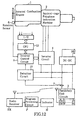
- Figures 1 and 2 show a control system for a vehicle-mounted battery, and its distinguishing features are that it comprises squirrel-cage polyphase induction machine 2 serving as a polyphase alternating current rotating machine coupled to internal combustion engine 1 serving as the driving gear of the vehicle, inverter circuit 4 provided between this squirrel-cage polyphase induction machine 2 and secondary cell circuit 3 mounted on the vehicle, said inverter circuit 4 performing AC-to-DC or DC-to-AC conversion, and inverter control circuit 5 serving as a program control circuit for controlling this inverter circuit 4; and also comprises detection circuit 13 as means for measuring the current and voltage of secondary cell circuit 3 during discharge and during charging; and inverter control circuit 5 comprises means for controlling, via inverter circuit 4 and on the basis of the voltage and current information measured by detection circuit 13, the charging current and discharging current, or one or other of these, of secondary cell circuit 3.
- inverter control circuit 5 comprises means for controlling, via inverter circuit 4 and on the basis of the voltage and current information measured by detection circuit 13, the charging current and discharging
- Inverter control circuit 5 comprises inverter control unit 50 for controlling inverter circuit 4, and memory 52 for holding information regarding current and voltage during discharge (discharge IV characteristics) and current and voltage during charging (charging IV characteristics).
- the hybrid car (HIMR) illustrated in Fig. 1 will now be explained.
- This vehicle is constituted in such manner that three-phase alternating current squirrel-cage polyphase induction machine 2 is coupled to the crankshaft of internal combustion engine 1, large secondary cell circuit 3 is mounted on the vehicle, this secondary cell circuit 3 and squirrel-cage polyphase induction machine 2 are coupled by means of bidirectional inverter circuit 4 which performs AC-to-DC or DC-to-AC conversion, and this inverter circuit 4 is controlledby inverter control circuit 5.
- Detection circuit 13 inputs the voltage of secondary cell circuit 3 and the current of current detector 7 to inverter control circuit 5.
- Inverter control circuit 5 controls inverter circuit 4 in accordance with the inputs from detection circuit 13, rotation sensor 6 and CPU 12.
- Inverter control circuit 5 controls inverter circuit 4 in such manner that when the vehicle starts or accelerates, the rotating magnetic field applied to this squirrel-cage polyphase induction machine 2 is controlled so that squirrel-cage polyphase induction machine 2 constitutes an electric motor, and when the vehicle decelerates, the rotating magnetic field applied to squirrel-cage polyphase induction machine 2 is controlled so that squirrel-cage polyphase induction machine 2 constitutes a generator.
- the control performed by this system is such that secondary cell circuit 3 discharges when squirrel-cage polyphase induction machine 2 is utilized as an electric motor, and charges when induction machine 2 is utilized as a generator. In other words, this system is controlled to provide regenerative braking. It is also possible to operate internal combustion engine 1 when the hybrid car is stationary, with the sole object of charging secondary cell circuit 3.
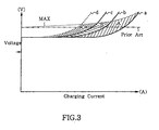
- Fig. 3 shows the charging characteristics of the secondary cell circuit, with charging current plotted along the horizontal axis and voltage along the vertical axis.
- the charging characteristics illustrated in Fig. 3 are held in memory 52 of inverter control circuit 5.
- curve a shows the situation in which the cells of secondary cell circuit 3 are new and have been slightly charged.
- Curve b shows the situation in which the cells of secondary cell circuit 3 are new and have been charged a medium amount.
- Curve c shows the situation in which the cells of secondary cell circuit 3 are new and have been fully charged.
- Curve d shows the situation in which deterioration of the unit cells of secondary cell circuit 3 has advanced to an extent where replacement is required.
- the upper limit MAX shows the voltage at which charging is ended and at which the control system of this first embodiment of the invention performs control.
- This upper limit MAX rises to the right in Fig. 3, in contrast to the prior art case shown by the dash and dotted line.
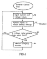
- Fig. 4 is a flowchart showing the operating flow of the inverter control unit when charging is carried out.
- the current and voltage values at this time are input from detection circuit 13 to inverter control unit 50 (S1).
- the region A, B or C to which secondary cell circuit 3 presently belongs is specified in accordance with these current and voltage values (S2). Namely, the present current and voltage values are compared with the charging characteristics shown in Fig. 3 and which are held in memory 52, and what sort of condition secondary cell circuit 3 is in is grasped. If secondary cell circuit 3 falls within region A, the unit cells of secondary cell circuit 3 are new and have been slightly charged. If it falls within region B, the unit cells of secondary cell circuit 3 are new and have been moderately charged. If it falls within region C, deterioration of the unit cells of secondary cell circuit 3 has proceeded to an extent where replacement is required. At the same time, the region A, B or C within which secondary cell circuit 3 falls can be indicated externally.
- the display can indicate that "charging is required”; if it falls within region B the display can indicate "normal”, and if it falls within region C the display can indicate that "cell replacement is required”.
- the value of the upper limit MAX changes according to which region A, B or C the secondary cell circuit belongs. If the voltage value is greater than the upper limit MAX for the region A, B or C to which the secondary cell circuit belongs (S3), charging current increase is restricted (S4). The present value of the voltage can be maintained by restricting any increase in the charging current.
- the charging current is controlled by using inverter circuit 4 to change the speed of rotation of the rotating magnetic field applied to squirrel-cage polyphase induction machine 2. Namely, if the speed of rotation of the rotating magnetic field of squirrel-cage polyphase induction machine 2 is made smaller than the rotational speed of the crankshaft of internal combustion engine 1, squirrel-cage polyphase induction machine 2 acts as a generator. In order to limit the charging current, the quantity of electricity generated by squirrel-cage polyphase induction machine 2 acting as a generator can be decreased if the rotational frequency of the rotating magnetic field of squirrel-cage polyphase induction machine 2 approaches the rotational frequency of the crankshaft, or in other words if the amount of slip is reduced.
- Fig. 5 shows the discharge characteristics of secondary cell circuit 3, with discharge current plotted along the horizontal axis and voltage along the vertical axis.
- the discharge characteristics illustrated in Fig. 5 are held in memory 52 of inverter control circuit 5.
- Curve e shows the situation in which the unit cells of secondary cell circuit 3 are new and fully charged.
- Curve f shows the situation in which the unit cells of secondary cell circuit 3 are new and have been moderately charged.
- Curve g shows the situation in which the unit cells of secondary cell circuit 3 are new and are poorly charged.
- Curve h shows the situation in which deterioration of the cells of secondary cell circuit 3 has advanced to an extent where replacement is required.
- the lower limit MIN shows the terminal voltage at which over-discharge will result if discharge continues beyond this limit.
- this lower limit MIN slopes down to the right in contrast to the prior art case shown by the dash and dotted line. This shows that when a battery is new and fully charged, the limiting voltage for discharge can be set comparatively low. Conversely, it shows that when battery deterioration has advanced to an extent where replacement is required, the limiting voltage for discharge is comparatively high, or in other words a large discharge current cannot be obtained.
- Fig. 6 is a flowchart showing the operating flow of the inverter control unit when discharging is carried out in the first comparative example.
- the current and voltage values at this time are input from detection circuit 13 to inverter control unit 50 (S11).
- the region E, F or G to which secondary cell circuit 3 presently belongs is specified in accordance with these current and voltage values (S12). Namely, the present current and voltage values are compared with the discharge characteristics shown in Fig. 5 and which are held in memory 52, and the state of deterioration and state of charging of the cells of secondary cell circuit 3 are detected.
- the results of the detection indicate that the cells fall within region E, the cells of secondary cell circuit 3 are new and fully charged. If they fall within region F, the cells of secondary cell circuit 3 are new and moderately charged. If they fall within region G, the deterioration of the cells of secondary cell circuit 3 has advanced to an extent where replacement is required.
- the region E, F or G within which the cells fall can be indicated externally. Namely, if the cells fall within region E the display can indicate that "discharging is required", whereas if they fall within region F the display can indicate "normal”, and if the cells fall within region G the display can indicate that "cell replacement is required”.
- the value of the lower limit MIN changes according to which region E, F or G the cells belong. If the voltage value is below the lower limit MIN for the region E, E or G to which the cells belong (S13), discharging current increase is restricted (S14). The present value of the voltage can be maintained by restricting any increase in the discharge current.
- the discharge current is controlled by using inverter circuit 4 to change the speed of rotation of the rotating magnetic field applied to squirrel-cage polyphase induction machine 2. Namely, if the speed of rotation of the rotating magnetic field of squirrel-cage polyphase induction machine 2 is larger than the rotational speed of the crankshaft of internal combustion engine 1, squirrel-cage polyphase induction machine 2 acts as an electric motor. In order to limit the discharge current, the power consumed by squirrel-cage polyphase induction machine 2 acting as an electric motor can be decreased if the rotational frequency of the rotating magnetic field of squirrel-cage polyphase induction machine 2 approaches the rotational frequency of the crankshaft, or in other words if the amount of slip is reduced.
- the upper limit for terminal voltage during charging is controlled adaptively in accordance with the state of deterioration of the battery
- the lower limit for terminal voltage during discharge is controlled adaptively in accordance with the state of deterioration of the battery.
- battery life can be increased.
- the state of deterioration can be controlled for each unit cell individually.
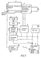
- Fig. 7 is a block diagram showing the overall configuration of this second embodiment.
- a battery sensor is provided for each of a plurality of unit cells comprising secondary cell circuit 3, and this battery sensor detects the terminal voltage of the individual unit cell.
- the results of these detections are transmitted as radio signals by radio transmitters TX 1 to TX n belonging to the respective battery sensors.
- radio receiver RX receives radio signals from radio transmitters TX 1 to TX n belonging to the respective battery sensors.
- radio receiver RX are input to inverter control circuit 5 as voltage information pertaining to the individual unit cells.
- Inverter control circuit 5 decides whether or not there are any unit cells at an advanced stage of deterioration, this decision being made in accordance with the voltage information from each unit cell and current information from current detector 7.
- the voltage at which charging is ended and the voltage at which discharge is ended are set to suit the characteristics of this cell.
- the storage capacity of the other unit cells in which deterioration is not advanced cannot be utilized 100% efficiently, but it is possible to avoid accelerated deterioration of the unit cell in which deterioration has already proceeded.
- an external display of information relating to a unit cell in which deterioration is advanced can prompt the replacement of that unit cell.
- Fig. 8 is a block diagram showing the configuration of the essential parts of this second comparative example.
- N unit cells B 1 to B n are connected in series and provided with respective battery sensors VD 1 to VD n .
- Battery sensors VD 1 to VD n are respectively provided with radio transmitters TX 1 to TX n .
- the radio signals transmitted from radio transmitters TX 1 to TX n are received by radio receiver RX.
- the voltage values of each battery sensor VD 1 to VD n which are output from radio receiver RX are input to inverter control circuit 5, and the current value detected by current detector 7 is input to inverter control circuit 5 via detection circuit 13.
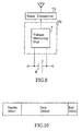
- Fig. 9 is a block diagram showing the configuration of a battery sensor in this second comparative example.
- Voltage measuring unit V measures the terminal voltage of unit cell B. This measured value is converted to a radio signal and transmitted by radio transmitter TX.
- Fig. 10 shows the frame structure of the radio signal in the second comparative example of the present invention.
- radio transmitter TX intermittently transmits, at 64kb/s, a data signal with a 32-bit frame structure of the sort shown in Fig. 10.
- An ID which has been individually allocated to each transmitter TX is transmitted in the header.
- Receiver RX can therefore identify from which transmitter TX a received frame has been transmitted.
- a mobile phone cell was adapted and used for this arrangement.
- the aforementioned period t is set in advance to a different value for each radio transmitter TX.
- the time for one transmission is approximately 20 ms.
- Period t is set in the range from 20 to 60 seconds so as to differ slightly for each transmitter TX.
- radio receiver RX can receive the signal of each radio transmitter TX individually even if the transmission timings of the plurality of radio transmitters TX were to coincide, because in the next period the transmission timing would differ.
- a period is set to 20 seconds, then a time of 20 ms, within which one radio transmitter TXi is transmitting, is one thousandth of the period. Accordingly, if radio transmitters TX 1 to TX n respectively connected to twenty-five unit cells B 1 to B n transmit with random timing, there is an approximately 1 in 400 chance of a collision. Even if there were a collision, because the period t varies for each transmitter, the two signals could be received separately in the next period without collision.
- Fig. 11 is a flowchart showing the operating flow of the inverter control unit in the second comparative example of the present invention.
- the value of the current detected by current detector 7 is input via detection circuit 13 to inverter control unit 50 (S21).
- the value of the voltage of each unit cell B 1 to B n is input via battery sensors VD 1 to VD n , radio transmitters TX 1 to TX n , and radio receiver RX (S22).
- the region within which each unit cell B 1 to B n falls is specified (S23), as was explained in detail in the description of the first comparative example.
- the specified regions can also be indicated externally. On the basis of these results, it is decided whether or not there are any deteriorated cells (S24).
- unit cells B 1 to B n constituting secondary cell circuit 3 are unit cells at an advanced stage of deterioration, it is possible to avoid further advance of deterioration due to overcharging or over-discharging. Moreover, making an external display of the state of deterioration can serve as a prompt for a driver or supervisor to replace any deteriorated unit cells as a matter of urgency.
- this second comparative example can obtain the same effect as the first embodiment.
- voltage information is transmitted by radio signals, direct contact with the high-voltage battery as part of battery management is eliminated, thereby providing improved safety.
- information which includes the value of the current and the temperature in addition to the voltage, thereby enabling detailed control data to be obtained.
- the hybrid car (HIMR) illustrated in Fig. 12 will now be explained.
- This vehicle is constituted in such manner that three-phase alternating current squirrel-cage polyphase induction machine 2 is coupled to the crankshaft of internal combustion engine 1, large secondary cell circuit 3 is mounted on the vehicle, this secondary cell circuit 3 and squirrel-cage polyphase induction machine 2 are coupled by means of bidirectional inverter circuit 4, and this inverter circuit 4 is controlled by inverter control circuit 5 which uses program control.
- Detection circuit 13 inputs the voltage of secondary cell circuit 3 and the current of current detector 7 to inverter control circuit 5.
- Inverter control circuit 5 controls inverter circuit4 in accordance with the inputs from detection circuit 13, rotation sensor 6 and CPU 12.
- Inverter control circuit 5 controls inverter circuit 4 in such manner that when the vehicle starts or accelerates, the rotating magnetic field applied to this squirrel-cage polyphase induction machine 2 is controlled so that squirrel-cage polyphase induction machine 2 constitutes an electric motor, and when the vehicle decelerates, the rotating magnetic field applied to squirrel-cage polyphase induction machine 2 is controlled so that squirrel-cage polyphase induction machine 2 constitutes a generator.
- the control performed by this system is such that secondary cell circuit 3 discharges when squirrel-cage polyphase induction machine 2 is utilized as an electric motor, and charges when induction machine 2 is utilized as a generator. In other words, this system is controlled to provide regenerative braking. It is also possible to operate internal combustion engine 1 when the hybrid car is stationary, with the sole object of charging secondary cell circuit 3.
- Secondary cell circuit 3 of an actual HIMR operates at 300V, this being obtained by connecting twenty-five 12V automobile lead storage batteries in series.
- the explanation given here is not restricted to 12 volts or twenty-five batteries. Instead, in order to make the situation easy to understand in general terms, an explanation will be given of the case where n unit cells B 1 to B n are connected in series.
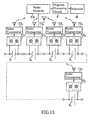
- the third comparative example of the present invention is an information transmission arrangement for a vehicle-mounted battery, and its distinguishing features are that, as shown in Fig. 13, unit cells B 1 to B n are respectively provided with battery sensors VD 1 to VD n as sensors for detecting voltage information relating to these unit cells B 1 to B n , and radio transmitters TX 1 to TX n for transmitting radio signals which have been modulated by the output of these battery sensors VD 1 to VD n ; and radio receiver RX for receiving these radio signals is disposed in or in the vicinity of the battery compartment; and separate information relating to each unit cell B 1 to B n is received at this radio receiver RX.
- the output of radio receiver RX is displayed via program processing circuit P on indicator M.
- battery sensor VD has voltage measuring unit V which measures the voltage of unit cell B, and also has first preset value detection unit TH 1 and second preset value detection unit TH 2 , and appurtenant to these, red lamp R and green lamp G.
- radio transmitter TX intermittently transmits, at 64kb/s, a data signal with a 32-bit frame structure of the sort shown in Fig. 15.
- An ID which has been individually allocated to each transmitter TX is transmitted in the header.
- Receiver RX can therefore identify from which transmitter TX a received frame has been transmitted.
- a mobile phone cell was adapted and used for this arrangement.
- the aforementioned period t is set in advance to a different value for each radio transmitter TX.
- the time taken to transmit one frame of the sort shown in Fig. 15 is approximately 20 ms.
- Period t is set in the range from 20 to 60 seconds so as to differ slightly for each transmitter TX.
- radio receiver RX can receive the signal of each radio transmitter TX individually even if the transmission timings of the plurality of radio transmitters TX were to coincide, because in the next period the transmission timing would differ.
- a period is set to 20 seconds, then a time of 20 ms, within which one radio transmitter TXi is transmitting, is one thousandth of the period. Accordingly, if radio transmitters TX 1 to TX n respectively connected to twenty-five unit cells B 1 to B n transmit with random timing, there is an approximately 1 in 400 chance of a collision. Even if there were a collision, because the period t varies for each transmitter, the two signals could be received separately in the next period without collision.
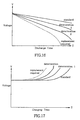
- Fig. 16 shows the relation between discharge characteristics and deterioration of unit cells B 1 to B n , with discharge time (T) taken along the horizontal axis and voltage (V) along the vertical axis. The characteristics shown are based on obtaining a fixed discharge current at a fixed load.
- Fig. 17 shows the relation between charging characteristics and deterioration of unit cells B 1 to B n , with charging time (T) taken along the horizontal axis and voltage (V) taken along the vertical axis.
- the characteristics shown are based on charging using a fixed charging current. As Fig. 16 shows, it is found that as deterioration advances, discharge is accompanied by more rapid voltage drop. As Fig. 17 shows, it is found that as deterioration advances, voltage increases, and charging is completed, within a shorter time.
- the voltage of unit cells B 1 to B n changes according to whether the cells are being charged or discharged (cell polarity), and according to the value of the cell current. Assuming that the standard voltage of unit cells B 1 to B n is 12V, it is found that if charging and discharging are repeated in cells of a certain type with the cells in a normal state, their terminal voltage varies between 11.4V and 13.2V. It is therefore useful for example to take 11.4V as the voltage at which charging is required (i.e., the first preset value) and to take 13.2V as the voltage at which charging is ended (i.e., the second preset value). These two preset values should be set in accordance with the properties of the cells, and should include a margin according to how the cells are used.
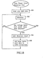
- Fig. 18 is a flowchart showing the operating flow of first preset value detection unit TH 1 in this third comparative example of the present invention.
- any currently held data is first of all reset (S31).
- the respective voltage values 18, of unit cells B 1 to B n are then detected (S32) and when a voltage value equal to or below the first preset value has been detected (S33), this result is held (S34), red lamp R lights, and the data is sent to transmitter TX (S35).
- a voltage of below the first preset value (11.4V) is generally detected when a current is being extracted from the battery, namely, when a load is being applied to unit cells B 1 to B n .
- red lamp R operates as follows. An over-discharge condition occurs In unit cells B 1 to B n when a load is applied, and for any unit cells B 1 to B n at which the voltage has decreased to below the first preset value, the red lamp will continue to light even though the terminal voltage rises again. Subsequently, if the voltage increases further and reaches the second preset value, green lamp G lights, but even then the red lamp continues to light.
- the data sent to radio transmitter TX is sent only once.
- Fig. 19 is a flowchart showing the operation of second preset value detection unit TH 2 of the third comparative example of the present invention.
- any currently held data is first of all reset (S41).
- the voltage values of each unit cell B 1 to B n are then detected (S42) and if a voltage value equal to or greater than the second preset value is detected (S43), this result is held (S44), and green lamp G lights and the data is sent to radio transmitter TX (S45).
- Green lamp G lights when the terminal voltage of a unit cell B 1 to B n exceeds the second preset value. In this example, green lamp G remains lit as well. Green lamp G lights when overcharging occurs in a unit cell B 1 to B n . Thereafter, even if discharge is carried out and the overcharging condition is eliminated, green lamp G remains lit.
- the data sent to radio transmitter TX is sent only once.
- Red lamp R and green lamp G are not directly related to the present invention.
- the driver or supervisor can ascertain the state of unit cells B 1 to B n by means of the lighting of the red lamps and the green lamps.
- the red lamp and green lamp of that unit cell B i will tend to light before those of the other unit cells, and therefore a supervisor can perform efficient inspection by simply inspecting unit cell B i on which the red lamp and the green lamp are lit.
- Fig. 20 is a flowchart showing the operating flow pertaining to detection of the first preset value by the program processing circuit in this third comparative example. If information relating to the detection of the first preset value is input to program processing circuit P (S51), it is decided whether the number of unit cells at which the first preset value has been detected exceeds a threshold (S52). If the threshold is exceeded, an indication that charging is required is output to indicator M (S53). Indicator M is a liquid crystal display panel provided at the driver's seat.
- Program processing circuit P outputs to indicator M a display for making information to this effect known to the driver or supervisor.
- Fig. 21 is a flowchart showing the operating flow pertaining to detection of the second present value by the program processing circuit in this third comparative example. If information relating to the detection of the second preset value is input to program processing circuit P (S61), it is decided whether the number of unit cells at which the second preset value has been detected exceeds a threshold (S62). If the threshold is exceeded, an indication that discharging is required is output to indicator M (S63).
- Program processing circuit P outputs to indicator M a display for making information to this effect known to the driver or supervisor.
- this indicator M is displayed at the driver's seat where it prompts the driver to drive appropriately.
- it can be utilized to modify the control state by being applied to CPU 12 shown in Fig. 12. Namely, when the battery is only slightly charged, it is controlled so that the contribution of internal combustion engine 1 during acceleration is increased, whereas when the battery is well charged the contribution of the electric motor during acceleration is increased. The battery is also controlled so that when the battery is only slightly charged, the contribution of regenerative braking during deceleration is increased and more braking energy is regenerated in the battery, whereas when the battery is well charged the contribution of regenerative braking during deceleration is decreased and energy is dissipated by frictional braking.
- Fig. 22 is a flowchart showing another operating flow pertaining to the detection of the second preset value by program processing circuit P in this third comparative example of the present invention. If information relating to the detection of the second preset value is input to program processing circuit P (S71), the time of this detection is recorded (S72). The variability of these second preset value detection times is also detected over the plurality of unit cells B (S73). If there is a unit cell B i for which this variability deviates by more than a certain threshold from the average range of variability within which the great majority of other unit cells B are contained (S74), battery deterioration is indicated for this unit cell B i (S75).
- a cell in which deterioration is advanced generally has a shorter charging and discharging time than a cell which has not deteriorated.
- Cells in which deterioration is advanced can therefore be extracted by noticing any cells for which charging is completed particularly soon compared with other cells.
- the time at which charging is completed can be detected by recording when the second preset value is detected. This can therefore be utilized to make a cell with a specific deterioration known to the driver or supervisor, by indicating on indicator M any cell for which the time required for completion of charging is considerably shorter than other cells.
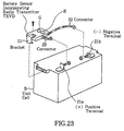
- FIG. 23 serves to explain how battery sensor TXVD, which incorporates a radio transmitter, is attached to unit cell B in this third embodiment.
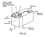
- Fig. 24 shows battery sensor TXVD, incorporating a radio transmitter, after it has been attached to unit cell B in this third comparative example.
- Battery sensor, TXVD, which incorporates a radio transmitter, and switching circuit SW are connected on top of unit cell B to terminals 21a and 21b by connectors 22, and are fixed to the casing of unit cell B by bracket 11.
- Fig. 25 shows unit cells B mounted on a vehicle in this third comparative example of the present invention.
- a plurality of unit cells B are mounted in centralized manner on battery carrier 31 and are housed in a battery compartment provided behind opening and closing door 32.
- the driver or supervisor can inspect unit cells B by pulling out battery carrier 31.
- receiver RX and indicator M are provided adjacent to opening and closing door 32, thereby enabling the condition of unit cells B to be inspected without pulling out battery carrier 31.
- FIG. 26 An example of the installation of indicator M in this third comparative example of the present invention is shown in Fig. 26 and Fig. 27.
- the driver or supervisor can ascertain the state of unit cells B, without opening the battery compartment, by means of radio receiver RX and indicator M installed at the driver's seat, and via radio receiver RX' and indicator M installed in the battery compartment, and antenna cable 24.
- indicator M set up at the driver's seat as shown in Fig. 27 enables the driver to ascertain, while driving, whether charging and discharging are required or not, and the state of deterioration of unit cells B.
- the present invention makes maintenance and inspection easy and can serve to increase the working life of batteries. It can also simplify battery maintenance. Further, the present invention enables maintenance personnel to make measurements without touching live parts of the battery. It also enables the state of deterioration of the battery to be found while the battery is in use. In other words, the state of a battery mounted on an electric vehicle can be detected while the vehicle is operating.
- Fig. 28 is a block diagram showing the overall configuration of this embodiment, of which the object is to perform still more detailed control by providing current measuring unit CD so that control is based on current as well as voltage.
- unit cells B 1 to B n are connected electrically in series, only one current measuring unit CD is provided in this series-connected circuit.
- the current measuring unit CD used in this embodiment does not cut the series-connected circuit. Instead, current is measured by providing a Hall element in proximity to the current path. Accordingly, the state of deterioration of unit cells B 1 to B n can be detected by measuring voltage and current.
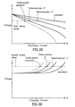
- Fig. 29 and Fig. 30 show the relation between charging and discharging characteristics and deterioration in unit cells B 1 to B n in this embodiment of the present invention, with discharge current (A) taken along the horizontal axis and voltage (V) along the vertical axis.
- Fig. 30 shows the relation between charging characteristics and deterioration of unit cells B 1 to B n in this embodiment, with charging current (A) taken along the horizontal axis and voltage (V) along the vertical axis.
- the voltage drop accompanying an increase in the discharge current becomes larger as deterioration proceeds.
- Fig. 30 the voltage rise accompanying an increase in charging current becomes larger as deterioration proceeds.
- a unit cell in an advanced stage of deterioration has a smaller storage capacity.
- Program processing circuit P has a memory which stores the relations between charging and discharging characteristics and deterioration shown in Fig. 29 and Fig. 30, and can detect the state of deterioration of unit cells B 1 to B n from the relation between a first preset value or a second preset value, these being sent as radio signals, and the corresponding value of the electric current.
- the results of this detection are displayed on indicator M as for example "unit cell B i : deterioration 1", "unit cell B j : deterioration 2", "unit cell B m : replacement required", and so forth.
- FIG. 31 shows the overall configuration of this fourth comparative example
- Fig. 32 is a block diagram showing the configuration of a battery sensor in this fourth comparative example.
- the distinguishing feature of this fourth comparative example is that it provides temperature sensors T 1 to T n for respective unit cells B 1 to B n .
- the data signal transmitted by radio transmitter TX contains, as well as the voltage information explained in the third comparative example, information relating to temperature as measured by temperature sensor T.
- Program processing circuit P can detect the state of deterioration of individual unit cells B 1 to B n in accordance with this voltage information and temperature information transmitted via radio receiver RX, and in accordance with the current information obtained from current measuring unit CD. In other words, it can detect the state of deterioration by comparing the voltage and current information with the volt-ampere characteristics shown in Fig. 29 and Fig. 30 in the manner indicated in the embodiment, but if there are a plurality of unit cells exhibiting equal volt-ampere characteristics, it can refer to the temperature information and specify a unit cell with a higher temperature than other unit cells as a unit cell in which deterioration is particularly advanced. The results of this detection are displayed on indicator M as "unit cell B i : deterioration I", "unit cell B j : deterioration 2", "unit cell B m : replacement required”, and so forth.
Landscapes
- Engineering & Computer Science (AREA)
- Power Engineering (AREA)
- Transportation (AREA)
- Mechanical Engineering (AREA)
- Chemical & Material Sciences (AREA)
- General Chemical & Material Sciences (AREA)
- Chemical Kinetics & Catalysis (AREA)
- Life Sciences & Earth Sciences (AREA)
- Electrochemistry (AREA)
- Sustainable Development (AREA)
- Sustainable Energy (AREA)
- Combustion & Propulsion (AREA)
- Manufacturing & Machinery (AREA)
- General Physics & Mathematics (AREA)
- Physics & Mathematics (AREA)
- Microelectronics & Electronic Packaging (AREA)
- Health & Medical Sciences (AREA)
- General Health & Medical Sciences (AREA)
- Medical Informatics (AREA)
- Secondary Cells (AREA)
- Charge And Discharge Circuits For Batteries Or The Like (AREA)
- Electric Propulsion And Braking For Vehicles (AREA)
Abstract
Claims (2)
- Système de commande couplé à une batterie embarquée sur un véhicule, le système comprenant une machine tournante à courant alternatif polyphasé (2) couplée au pignon d'entraínement d'un véhicule, un circuit inverseur (4) disposé entre cette machine tournante à courant alternatif polyphasé (2) et la batterie embarquée sur le véhicule, ledit inverseur effectuant la conversion CA vers CC ou CC vers CA, un circuit de commande par programme (5) pour commander ce circuit inverseur (4), et un moyen (13) pour mesurer le courant et la tension de la batterie précitée durant la décharge et durant la charge, le circuit de commande par programme (5) comprenant un moyen pour commander, via l'inverseur précité et à partir des informations de tension et de courant mesurées par le moyen précité, le courant de charge et/ou le courant de décharge de la batterie ;
et qui est caractérisé en ce que la batterie précitée est munie de détecteurs de batterie pour détecter la tension aux bornes et le courant des cellules unitaires (B1 à Bn) de la batterie, la sortie de détection de ces détecteurs de batterie (VD1 à VDnCD) étant fournie au circuit de commande par programme (5), le circuit de commande par programme comprenant un moyen poura) déterminer à partir des sorties de détection des détecteurs de batterie (VD1 à VDnCD) à quelle région, parmi une pluralité de régions d'état de détérioration de cellule, chaque cellule unitaire appartient ; et,b) ajuster le courant de charge ou de décharge selon les besoins, si l'une quelconque des cellules unitaires est dans un état détérioré, afin que la charge ou la décharge soit adaptée à la ou aux cellules détériorées. - Système de commande selon la revendication 1, dans lequel le détecteur de batterie comprend des détecteurs de température (T1 à Tn) pour détecter les informations liées à la température des cellules unitaires.
Applications Claiming Priority (7)
| Application Number | Priority Date | Filing Date | Title |
|---|---|---|---|
| JP15570796A JP3351682B2 (ja) | 1996-06-17 | 1996-06-17 | 車載電池の情報伝達装置 |
| JP15570796 | 1996-06-17 | ||
| JP155707/96 | 1996-06-17 | ||
| JP16191696 | 1996-06-21 | ||
| JP161916/96 | 1996-06-21 | ||
| JP16191696A JP3351683B2 (ja) | 1996-06-21 | 1996-06-21 | 車載電池の制御装置 |
| PCT/JP1997/001980 WO1997048569A1 (fr) | 1996-06-17 | 1997-06-10 | Regulateur pour batterie d'accumulateurs embarquee sur un vehicule |
Publications (3)
| Publication Number | Publication Date |
|---|---|
| EP0845383A1 EP0845383A1 (fr) | 1998-06-03 |
| EP0845383A4 EP0845383A4 (fr) | 1998-10-07 |
| EP0845383B1 true EP0845383B1 (fr) | 2004-09-22 |
Family
ID=26483636
Family Applications (1)
| Application Number | Title | Priority Date | Filing Date |
|---|---|---|---|
| EP97925305A Expired - Lifetime EP0845383B1 (fr) | 1996-06-17 | 1997-06-10 | Regulateur pour batterie d'accumulateurs embarquee sur un vehicule |
Country Status (5)
| Country | Link |
|---|---|
| EP (1) | EP0845383B1 (fr) |
| KR (1) | KR100508788B1 (fr) |
| CN (1) | CN1139502C (fr) |
| DE (1) | DE69730802T2 (fr) |
| WO (1) | WO1997048569A1 (fr) |
Cited By (1)
| Publication number | Priority date | Publication date | Assignee | Title |
|---|---|---|---|---|
| US8011467B2 (en) | 2003-03-28 | 2011-09-06 | Mitsubishi Denki Kabushiki Kaisha | Vehicle power supply system |
Families Citing this family (16)
| Publication number | Priority date | Publication date | Assignee | Title |
|---|---|---|---|---|
| JP4432168B2 (ja) * | 1998-11-30 | 2010-03-17 | ソニー株式会社 | 移動体搭載用バッテリ装置 |
| KR20030034936A (ko) * | 2001-10-29 | 2003-05-09 | 현대자동차주식회사 | 하이브리드 전기 차량의 배터리 점검장치 |
| DE10225658A1 (de) * | 2002-06-10 | 2003-12-24 | Delphi Tech Inc | Batteriesystem und Verfahren zur Übertragung einer Information über eine Batterieeigenschaft |
| DE102005024403A1 (de) * | 2005-05-27 | 2007-01-18 | Güttler, Gerhard, Prof. Dr. | Verfahren und Vorrichtung zum Einsparen von Energie in einem Fahrzeug |
| FR2889742B1 (fr) * | 2005-08-09 | 2007-10-19 | Accumulateurs Fixes | Systeme et procede de controle d'une batterie rechargeable |
| DE102007021921B4 (de) * | 2007-05-10 | 2009-03-19 | Siemens Ag | Vorrichtung zum Überwachen eines Energiespeichers |
| DE102007029847A1 (de) * | 2007-06-28 | 2009-01-02 | Siemens Ag | Energiespeichereinrichtung und Verfahren zu deren Betrieb |
| FR2920884B1 (fr) * | 2007-09-11 | 2009-11-27 | Peugeot Citroen Automobiles Sa | Procede d'estimation de l'etat de sante d'une batterie embarquee dans un vehicule automobile. |
| DE102007047823A1 (de) * | 2007-11-20 | 2009-05-28 | Zf Friedrichshafen Ag | Verfahren zur Entkopplung des Funktionsmoduls des Hybrid-Antriebsstrangs |
| DE102011002707A1 (de) | 2011-01-14 | 2012-07-19 | Siemens Aktiengesellschaft | Ladevorrichtung zum Laden eines Fahrzeugakkumulators |
| DE102012202751A1 (de) | 2012-02-23 | 2013-08-29 | Robert Bosch Gmbh | Batteriesensordatenübertragungseinheit und ein Verfahren zum Übertragen von Batteriesensordaten |
| US9522599B2 (en) * | 2012-03-19 | 2016-12-20 | GM Global Technology Operations LLC | Method for estimating parameters for a vehicle battery |
| CN102602388B (zh) * | 2012-03-29 | 2015-11-18 | 潍柴动力股份有限公司 | 一种优化混合动力发动机怠速下工况的方法和装置 |
| CN103887866B (zh) * | 2014-02-28 | 2016-02-03 | 成都宇能通能源开发有限公司 | 一种车载直流发电机最大输出功率跟踪隔离装置 |
| CN109895634A (zh) * | 2019-03-12 | 2019-06-18 | 中铁轨道交通装备有限公司 | 一种跨坐式单轨车辆车载电源的控制系统及方法 |
| KR20240022458A (ko) * | 2021-04-15 | 2024-02-20 | 씨피에스 테크놀로지 홀딩스 엘엘씨 | 지능형 납산 배터리 시스템 및 그 작동 방법 |
Family Cites Families (9)
| Publication number | Priority date | Publication date | Assignee | Title |
|---|---|---|---|---|
| US4305254A (en) * | 1980-02-20 | 1981-12-15 | Daihatsu Motor Co., Ltd. | Control apparatus and method for engine/electric hybrid vehicle |
| FR2589008B1 (fr) * | 1985-10-17 | 1994-10-21 | Cga Alcatel | Systeme de surveillance d'un ensemble d'accumulateurs electrochimiques et dispositif de surveillance pour un accumulateur |
| JPH03203501A (ja) * | 1989-12-27 | 1991-09-05 | Aisin Aw Co Ltd | 電動車両の電源切り換え制御方式 |
| JPH03115478U (fr) * | 1990-03-09 | 1991-11-28 | ||
| JP3235167B2 (ja) * | 1992-02-06 | 2001-12-04 | 株式会社タツノ・メカトロニクス | 電気自動車 |
| JP3331529B2 (ja) * | 1993-01-29 | 2002-10-07 | キヤノン株式会社 | 蓄電装置及び電力システム |
| JPH06261411A (ja) * | 1993-03-05 | 1994-09-16 | Hino Motors Ltd | 内燃機関の制動および補助動力装置 |
| JP3088900B2 (ja) * | 1994-04-01 | 2000-09-18 | 日野自動車株式会社 | 補助制動および補助動力装置 |
| JP3288928B2 (ja) * | 1996-06-14 | 2002-06-04 | 日野自動車株式会社 | 車載電池の制御装置 |
-
1997
- 1997-06-10 DE DE69730802T patent/DE69730802T2/de not_active Expired - Fee Related
- 1997-06-10 CN CNB971907250A patent/CN1139502C/zh not_active Expired - Fee Related
- 1997-06-10 KR KR1019970709921A patent/KR100508788B1/ko not_active IP Right Cessation
- 1997-06-10 EP EP97925305A patent/EP0845383B1/fr not_active Expired - Lifetime
- 1997-06-10 WO PCT/JP1997/001980 patent/WO1997048569A1/fr active IP Right Grant
Cited By (1)
| Publication number | Priority date | Publication date | Assignee | Title |
|---|---|---|---|---|
| US8011467B2 (en) | 2003-03-28 | 2011-09-06 | Mitsubishi Denki Kabushiki Kaisha | Vehicle power supply system |
Also Published As
| Publication number | Publication date |
|---|---|
| DE69730802T2 (de) | 2005-02-10 |
| KR100508788B1 (ko) | 2005-11-21 |
| CN1195325A (zh) | 1998-10-07 |
| CN1139502C (zh) | 2004-02-25 |
| EP0845383A1 (fr) | 1998-06-03 |
| WO1997048569A1 (fr) | 1997-12-24 |
| EP0845383A4 (fr) | 1998-10-07 |
| DE69730802D1 (de) | 2004-10-28 |
| KR19990028599A (ko) | 1999-04-15 |
Similar Documents
| Publication | Publication Date | Title |
|---|---|---|
| US5955865A (en) | Control system for a vehicle-mounted battery | |
| EP0845383B1 (fr) | Regulateur pour batterie d'accumulateurs embarquee sur un vehicule | |
| US5939861A (en) | Control system for on-vehicle battery | |
| EP0841208B1 (fr) | Controleur pour batterie de vehicule embarquee | |
| EP1293377B1 (fr) | Dispositif de commande d'accumulateur | |
| JP3351682B2 (ja) | 車載電池の情報伝達装置 | |
| US6501250B2 (en) | Device and method for controlling input/output of secondary battery | |
| JP4377164B2 (ja) | 蓄電装置の異常検出方法、蓄電装置の異常検出装置および蓄電システム | |
| US5965991A (en) | Control system for a vehicle-mounted battery | |
| US5659240A (en) | Intelligent battery charger for electric drive system batteries | |
| EP3723235A2 (fr) | Dispositif de protection et procédé de supercondensateur de système d'alimentation électrique de véhicule | |
| JP4066732B2 (ja) | バッテリ残容量推定方法 | |
| US20020084768A1 (en) | Method for controlling a charging state of a battery for an electric vehicle | |
| WO1990004188A1 (fr) | Moniteur servant a controler l'etat general d'une batterie d'automobile | |
| WO1999012044A2 (fr) | Temoin de charge de batterie | |
| KR100254424B1 (ko) | 하이브리드 전기 자동차 구동 장치 및 그 방법 | |
| JP3411753B2 (ja) | 車載電池の制御装置 | |
| JP3288927B2 (ja) | 車載電池の表示装置 | |
| CN113533993A (zh) | 电池组的状态判定装置及状态判定方法 | |
| JP3351683B2 (ja) | 車載電池の制御装置 | |
| JP2003045387A (ja) | 電池パックシステムおよび電池パックの劣化判定方法 | |
| JPH104603A (ja) | 車載用電池の表示装置 | |
| JP3281408B2 (ja) | 充電装置 | |
| KR980012693A (ko) | 자동차의 밧데리 과방전 방지방법 |
Legal Events
| Date | Code | Title | Description |
|---|---|---|---|
| PUAI | Public reference made under article 153(3) epc to a published international application that has entered the european phase |
Free format text: ORIGINAL CODE: 0009012 |
|
| 17P | Request for examination filed |
Effective date: 19980306 |
|
| AK | Designated contracting states |
Kind code of ref document: A1 Designated state(s): DE FR GB IT SE |
|
| A4 | Supplementary search report drawn up and despatched | ||
| AK | Designated contracting states |
Kind code of ref document: A4 Designated state(s): DE FR GB IT SE |
|
| 17Q | First examination report despatched |
Effective date: 20010214 |
|
| RAP1 | Party data changed (applicant data changed or rights of an application transferred) |
Owner name: HINO JIDOSHA KABUSHIKI KAISHA |
|
| GRAP | Despatch of communication of intention to grant a patent |
Free format text: ORIGINAL CODE: EPIDOSNIGR1 |
|
| GRAS | Grant fee paid |
Free format text: ORIGINAL CODE: EPIDOSNIGR3 |
|
| GRAA | (expected) grant |
Free format text: ORIGINAL CODE: 0009210 |
|
| AK | Designated contracting states |
Kind code of ref document: B1 Designated state(s): DE FR GB IT SE |
|
| PG25 | Lapsed in a contracting state [announced via postgrant information from national office to epo] |
Ref country code: IT Free format text: LAPSE BECAUSE OF FAILURE TO SUBMIT A TRANSLATION OF THE DESCRIPTION OR TO PAY THE FEE WITHIN THE PRESCRIBED TIME-LIMIT;WARNING: LAPSES OF ITALIAN PATENTS WITH EFFECTIVE DATE BEFORE 2007 MAY HAVE OCCURRED AT ANY TIME BEFORE 2007. THE CORRECT EFFECTIVE DATE MAY BE DIFFERENT FROM THE ONE RECORDED. Effective date: 20040922 |
|
| REG | Reference to a national code |
Ref country code: GB Ref legal event code: FG4D |
|
| REF | Corresponds to: |
Ref document number: 69730802 Country of ref document: DE Date of ref document: 20041028 Kind code of ref document: P |
|
| PG25 | Lapsed in a contracting state [announced via postgrant information from national office to epo] |
Ref country code: SE Free format text: LAPSE BECAUSE OF FAILURE TO SUBMIT A TRANSLATION OF THE DESCRIPTION OR TO PAY THE FEE WITHIN THE PRESCRIBED TIME-LIMIT Effective date: 20041222 |
|
| ET | Fr: translation filed | ||
| PLBE | No opposition filed within time limit |
Free format text: ORIGINAL CODE: 0009261 |
|
| STAA | Information on the status of an ep patent application or granted ep patent |
Free format text: STATUS: NO OPPOSITION FILED WITHIN TIME LIMIT |
|
| 26N | No opposition filed |
Effective date: 20050623 |
|
| PGFP | Annual fee paid to national office [announced via postgrant information from national office to epo] |
Ref country code: GB Payment date: 20060607 Year of fee payment: 10 |
|
| PGFP | Annual fee paid to national office [announced via postgrant information from national office to epo] |
Ref country code: FR Payment date: 20060608 Year of fee payment: 10 Ref country code: DE Payment date: 20060608 Year of fee payment: 10 |
|
| GBPC | Gb: european patent ceased through non-payment of renewal fee |
Effective date: 20070610 |
|
| REG | Reference to a national code |
Ref country code: FR Ref legal event code: ST Effective date: 20080229 |
|
| PG25 | Lapsed in a contracting state [announced via postgrant information from national office to epo] |
Ref country code: DE Free format text: LAPSE BECAUSE OF NON-PAYMENT OF DUE FEES Effective date: 20080101 |
|
| PG25 | Lapsed in a contracting state [announced via postgrant information from national office to epo] |
Ref country code: GB Free format text: LAPSE BECAUSE OF NON-PAYMENT OF DUE FEES Effective date: 20070610 |
|
| PG25 | Lapsed in a contracting state [announced via postgrant information from national office to epo] |
Ref country code: FR Free format text: LAPSE BECAUSE OF NON-PAYMENT OF DUE FEES Effective date: 20070702 |