EP0845145B1 - Zeigereinrichtung - Google Patents
Zeigereinrichtung Download PDFInfo
- Publication number
- EP0845145B1 EP0845145B1 EP97922898A EP97922898A EP0845145B1 EP 0845145 B1 EP0845145 B1 EP 0845145B1 EP 97922898 A EP97922898 A EP 97922898A EP 97922898 A EP97922898 A EP 97922898A EP 0845145 B1 EP0845145 B1 EP 0845145B1
- Authority
- EP
- European Patent Office
- Prior art keywords
- pointer
- light
- luminous
- reflecting surface
- hub
- Prior art date
- Legal status (The legal status is an assumption and is not a legal conclusion. Google has not performed a legal analysis and makes no representation as to the accuracy of the status listed.)
- Expired - Lifetime
Links
Images
Classifications
-
- G—PHYSICS
- G01—MEASURING; TESTING
- G01D—MEASURING NOT SPECIALLY ADAPTED FOR A SPECIFIC VARIABLE; ARRANGEMENTS FOR MEASURING TWO OR MORE VARIABLES NOT COVERED IN A SINGLE OTHER SUBCLASS; TARIFF METERING APPARATUS; MEASURING OR TESTING NOT OTHERWISE PROVIDED FOR
- G01D13/00—Component parts of indicators for measuring arrangements not specially adapted for a specific variable
- G01D13/22—Pointers, e.g. settable pointer
- G01D13/28—Pointers, e.g. settable pointer with luminescent markings
-
- G—PHYSICS
- G01—MEASURING; TESTING
- G01D—MEASURING NOT SPECIALLY ADAPTED FOR A SPECIFIC VARIABLE; ARRANGEMENTS FOR MEASURING TWO OR MORE VARIABLES NOT COVERED IN A SINGLE OTHER SUBCLASS; TARIFF METERING APPARATUS; MEASURING OR TESTING NOT OTHERWISE PROVIDED FOR
- G01D11/00—Component parts of measuring arrangements not specially adapted for a specific variable
- G01D11/28—Structurally-combined illuminating devices
-
- G—PHYSICS
- G12—INSTRUMENT DETAILS
- G12B—CONSTRUCTIONAL DETAILS OF INSTRUMENTS, OR COMPARABLE DETAILS OF OTHER APPARATUS, NOT OTHERWISE PROVIDED FOR
- G12B11/00—Indicating elements; Illumination thereof
- G12B11/04—Pointers; Setting-mechanisms therefor
Definitions
- the invention is based on a pointer device according to the genus Main claim.
- a pointer device is already known from DE 33 47 014 C2 known.
- This pointer device has one which is rotatably mounted about a pointer axis Pointer, which consists of transparent light-conducting material.
- the light of which is fixed is permanently mounted on the side of the pointer facing away from the viewer is coupled axially to the pointer axis in the light-conducting material of the luminous pointer.
- the light, which is coupled axially in this way, is directed into the radial via a light guide insert Direction of longitudinal extension of the pointer can be deflected.
- DE 34 25 029 A1 describes a lighting device in a measuring instrument is known in which a pointer of the measuring instrument has an intermediate part, the one light receiving section forms. Open cavities are formed in the pointer, that of reflective surfaces of an insert are limited. The reflective surfaces serve to to redirect the light of the pointer into the pointer flag.
- DE 32 01 571 A1 is a Display device with a hub that can be rotated about an axis in front of a dial and existing pointer arm known. The pointer has on the observer side directed light reflection surfaces that can be illuminated by a light source.
- the pointer device has the features of the main claim in contrast, the advantages that the luminance of a passive luminous pointer is significantly increased. This offers the advantage in cases where a very good one Illumination of the pointer is also necessary to use a passive luminous pointer can and to the use of a much more expensive active luminous pointer dispense.
- the arrangement makes the practically lossless total reflection of Rays that strike at a large angle to the surface normal with the additional reflection of rays at a small angle to meet the surface normal, combined.
- Embodiments of the invention are in the drawing shown and in the description below explained.
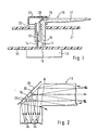
- 1 shows an embodiment of the Invention and
- Figure 2 shows the beam path of light in Embodiment according to FIG. 1.
- Figure 1 shows a pointer arrangement with a passive Luminescent hands. This is in contrast to the active Luminous hands, the light source is not in the pointer itself integrated, but the light is from a fixed Light source in the rotatable luminous pointer coupled.
- Figure 1 are on a circuit board 11th several LEDs 12 mounted, the here For the sake of simplicity, only a single light-emitting diode is shown is. These multiple light emitting diodes 12 are preferably approximately mounted at a distance of 60 ° on the circuit board and contacted.
- the luminous pointer 16 is fastened with its pointer hub 15.
- This pointer hub 15 and the luminous pointer 16 are in one piece formed from a light guide.
- the luminous pointer 16 itself consists of a right angle, radial section, which represents the pointer flags 17, and an axial section, which has a light fetch 18 forms.
- the light of the light emitting diodes 12 is axially in coupled the lightholder 18 and then on the mirror surface 19 by means of total reflection in the radial pointer flag 17 diverted. Parallel to the mirror surface 19 is with a a small distance from the mirror surface 19 Surface mirror 20 is provided.
- the Dial 21 On the viewer opposite side of the luminous pointer 16 is the Dial 21, which has an opening 22 through which the pointer hub 15 and the Lichtholer 18 passed are.
- the breakthrough 22 in the dial 16 the The pointer hub and the light fetch are through a cap 23 covered. This cap 23 is colored white on the inside, so that Light emerging from the pointer 16 back into the pointer is reflected back.
- the beam path for the light deflection from the axial Part of the luminous pointer 16 in the radial part of the Luminous pointer 16 is shown in Figure 2. Same parts are given the same reference numerals here.
- the schematic course of light propagation in the light-conducting material of the luminous pointer 16 is with the Arrows 24 indicated.
- the light comes out of here LED 12 not shown again and is in the axial light feeder 18 is coupled.
- the front mirror 20 is still provided.
- There a Part of the light rays from the LED due to Angle of incidence on the mirror surface 19 from the can leak light-conducting material is the Front mirror 20 provided.
- the surface mirror 20 can for example consist of a metallized plastic film (polycarbonate) are punched out and first into a designated one Forming the cap 23 inserted and initially fixed in this way become. With the insertion of the light guide it will then finally captured.
- a metallized plastic film polycarbonate
Landscapes
- Physics & Mathematics (AREA)
- General Physics & Mathematics (AREA)
- Details Of Measuring Devices (AREA)
Description
Claims (7)
- Zeigereinrichtung mit einem um eine Zeigerachse drehbar gelagerten Leuchtzeiger aus lichtleitendem Material, mit einer außerhalb des Leuchtzeigers festmontierten Lichtquelle, deren Licht parallel zu der Zeigerachse in den Leuchtzeiger eingekoppelt wird, wobei der Leuchtzeiger aus einem radialen Abschnitt, welcher eine Zeigerfahne bildet, und einem axialen Abschnitt, welcher einen Lichtholer bildet, besteht, dadurch gekennzeichnet, dass eine Umlenkung von Licht von dem axialen Abschnitt zu dem radialen Abschnitt über eine Spiegelfläche (19) zur Totalreflexion und einen zusätzlichen Oberflächenspiegel (20), der beabstandet zu der Spiegelfläche (19) angeordnet ist, derart erfolgt, dass die an der Spiegelfläche (19) nicht in Totalreflexion reflektierten, aus dem lichtleitenden Material des Leuchtzeigers (16) austretenden Lichtstrahlen (25) an dem Oberflächenspiegel (20) wieder durch die Spiegelfläche (19) hindurch in den Leuchtzeiger (16) hinein zurückreflektiert werden.
- Zeigereinrichtung nach Anspruch 1, dadurch gekennzeichnet, dass der zusätzliche Oberflächenspiegel (20) parallel zur Spiegelfläche (19) angebracht ist.
- Zeigereinrichtung nach einem der vorherigen Ansprüche, dadurch gekennzeichnet, dass der Oberflächenspiegel (20) aus einer metallisch bedampften Kunststofffolie besteht.
- Zeigereinrichtung nach einem der vorherigen Ansprüche, dadurch gekennzeichnet, dass die Lichtquelle (12) auf einer Leiterplatte (11) montiert ist.
- Zeigereinrichtung nach einem der vorherigen Ansprüche, dadurch gekennzeichnet, dass eine Zeigernabe (15) und der Leuchtzeiger (16) einteilig aus einem Lichtleiter geformt sind.
- Zeigereinrichtung nach einem der vorherigen Ansprüche, dadurch gekennzeichnet, dass auf der einem Betrachter abgewandten Seite des Leuchtzeigers (16) ein Zifferblatt (21) angeordnet ist.
- Zeigereinrichtung nach Anspruch 6, dadurch gekennzeichnet, dass in dem Zifferblatt (21) ein Durchbruch (22) zum Durchführen der Zeigernabe (15) und des Lichtholers (18) angeordnet ist und dass der Durchbruch (22), die Zeigernabe (15) und der Lichtholer (18) durch eine Kappe (23) abgedeckt sind.
Applications Claiming Priority (3)
| Application Number | Priority Date | Filing Date | Title |
|---|---|---|---|
| DE19624081A DE19624081A1 (de) | 1996-06-17 | 1996-06-17 | Zeigereinrichtung |
| DE19624081 | 1996-06-17 | ||
| PCT/DE1997/000935 WO1997049090A1 (de) | 1996-06-17 | 1997-05-09 | Zeigereinrichtung |
Publications (2)
| Publication Number | Publication Date |
|---|---|
| EP0845145A1 EP0845145A1 (de) | 1998-06-03 |
| EP0845145B1 true EP0845145B1 (de) | 2004-10-13 |
Family
ID=7797144
Family Applications (1)
| Application Number | Title | Priority Date | Filing Date |
|---|---|---|---|
| EP97922898A Expired - Lifetime EP0845145B1 (de) | 1996-06-17 | 1997-05-09 | Zeigereinrichtung |
Country Status (5)
| Country | Link |
|---|---|
| US (1) | US6032608A (de) |
| EP (1) | EP0845145B1 (de) |
| JP (1) | JPH11510913A (de) |
| DE (2) | DE19624081A1 (de) |
| WO (1) | WO1997049090A1 (de) |
Families Citing this family (23)
| Publication number | Priority date | Publication date | Assignee | Title |
|---|---|---|---|---|
| DE19828041A1 (de) | 1998-06-24 | 2000-01-05 | Mannesmann Vdo Ag | Zeigerinstrument |
| IT1303569B1 (it) * | 1998-09-01 | 2000-11-14 | Magneti Marelli Spa | Gruppo indice monoblocco retroilluminabile. |
| DE19956542A1 (de) * | 1999-11-24 | 2001-05-31 | Mannesmann Vdo Ag | Anzeigeinstrument, insbesondere in einem Kraftfahrzeug |
| DE10063875A1 (de) * | 2000-12-21 | 2002-07-04 | Siemens Ag | Anzeigeinstrument |
| JP2003302261A (ja) * | 2002-04-05 | 2003-10-24 | Yazaki Corp | 指針式指示装置 |
| DE10225946A1 (de) * | 2002-06-11 | 2003-12-24 | Borg Instr Ag | Zeiger mit Hohlwelle |
| JP4615931B2 (ja) * | 2004-08-18 | 2011-01-19 | 矢崎総業株式会社 | 指針 |
| US7458695B2 (en) * | 2005-06-20 | 2008-12-02 | Continental Automotive Systems Us, Inc. | High light-efficiency illumination cluster |
| US7404374B2 (en) * | 2006-11-07 | 2008-07-29 | Denso International America, Inc. | Gauge pointer and light guide structure |
| SE530699C2 (sv) * | 2006-12-21 | 2008-08-19 | Scania Cv Abp | Instrumentkluster för ett mororfordon |
| DE102007001737B4 (de) * | 2007-01-11 | 2012-10-11 | Audi Ag | Zeigeranordnung für ein Zeigerinstrument |
| US7665413B2 (en) * | 2007-04-27 | 2010-02-23 | Continental Automotive Systems Us, Inc. | Illuminated hub pointer |
| GB2450109B (en) * | 2007-06-12 | 2011-09-07 | Visteon Global Tech Inc | Backlit display |
| US20090038535A1 (en) * | 2007-08-07 | 2009-02-12 | Jorge Morales | Instrument Pointer Assembly |
| US8261686B2 (en) * | 2008-09-17 | 2012-09-11 | Continental Automotive Systems Us, Inc. | Flood illuminated cluster with telltales |
| US8016442B2 (en) * | 2009-01-27 | 2011-09-13 | Denso International America, Inc. | Illuminated indicating devices for instrument panels |
| US8225736B2 (en) * | 2009-01-27 | 2012-07-24 | Denso International America, Inc. | Hub glow pointer |
| US8579448B2 (en) * | 2010-01-25 | 2013-11-12 | Johnson Controls Technology Company | Pointer structure of an instrument cluster |
| US8935989B2 (en) * | 2011-03-31 | 2015-01-20 | Denso International America, Inc. | Backlit reflective pointer |
| CN102522125A (zh) * | 2011-11-04 | 2012-06-27 | 埃泰克汽车电子(芜湖)有限公司 | 一种汽车组合仪表总成 |
| WO2017147518A1 (en) * | 2016-02-26 | 2017-08-31 | Continental Automotive Systems, Inc. | Front pick-up illuminated pointer |
| EP3637200B1 (de) * | 2018-10-09 | 2022-09-14 | The Swatch Group Research and Development Ltd | Leuchtanzeigevorrichtung |
| CN117308064A (zh) * | 2022-06-24 | 2023-12-29 | 上海携福电器有限公司 | 具有发光端盖的个人护理用具 |
Citations (2)
| Publication number | Priority date | Publication date | Assignee | Title |
|---|---|---|---|---|
| DE3425029A1 (de) * | 1983-07-08 | 1985-01-31 | Yazaki Corp., Tokio/Tokyo | Beleuchtungseinrichtung in einem messinstrument |
| EP0295165A1 (de) * | 1987-05-25 | 1988-12-14 | Jaeger | Beleuchteter Zeiger, insbesondere für Instrumentenbrett |
Family Cites Families (19)
| Publication number | Priority date | Publication date | Assignee | Title |
|---|---|---|---|---|
| US2902970A (en) * | 1957-10-09 | 1959-09-08 | Avien Inc | Illuminated dial pointer |
| JPS5467454A (en) * | 1977-11-09 | 1979-05-30 | Nissan Motor | Meter with pointer |
| JPS5813693Y2 (ja) * | 1978-06-26 | 1983-03-17 | 日産自動車株式会社 | メ−タの指針 |
| US4339400A (en) * | 1981-05-11 | 1982-07-13 | Sorko Ram Paul A | Process for producing three-dimensional, mirrored acrylic articles |
| DE3201571A1 (de) * | 1982-01-20 | 1983-07-28 | Vdo Adolf Schindling Ag, 6000 Frankfurt | Anzeigeeinrichtung |
| DE3300270A1 (de) * | 1983-01-07 | 1984-07-12 | Vdo Adolf Schindling Ag, 6000 Frankfurt | Anzeigegeraet |
| DE3347014A1 (de) * | 1983-12-24 | 1985-07-04 | Vdo Schindling | Zeigereinrichtung |
| JPH0713572B2 (ja) * | 1987-01-23 | 1995-02-15 | 日産自動車株式会社 | メ−タ |
| DE3824391A1 (de) * | 1988-07-19 | 1990-01-25 | Vdo Schindling | Anzeigeinstrument |
| GB8917411D0 (en) * | 1989-07-29 | 1989-09-13 | Combined Optical Ind Ltd | Improvements in or relating to pointers |
| US4959759A (en) * | 1989-08-04 | 1990-09-25 | Delco Electronics Corporation | Automotive instrument display having a thickfilm electroluminescent lightpipe pointer |
| JPH03259714A (ja) * | 1990-03-09 | 1991-11-19 | Nippondenso Co Ltd | 計器の指針照明装置 |
| US5291851A (en) * | 1990-06-29 | 1994-03-08 | Yazaki Corporation | Gauge for automobile |
| FR2672676B1 (fr) * | 1991-02-13 | 1993-06-04 | Jaeger | Aiguille eclairante perfectionnee. |
| FR2710978B1 (fr) * | 1993-10-08 | 1995-12-29 | Jaeger | Ensemble indicateur à aiguille, aiguille pour celui-ci et application aux tableaux de bord de véhicules automobiles. |
| US5458082A (en) * | 1994-03-24 | 1995-10-17 | Delco Electronics Corp. | Tip to tail illuminated pointer |
| US5546888A (en) * | 1994-09-09 | 1996-08-20 | Delco Electronics Corporation | Surface mounted gauge with illuminated pointer |
| JP2584961B2 (ja) * | 1995-09-08 | 1997-02-26 | 株式会社カンセイ | 指示計器 |
| US5690049A (en) * | 1996-02-05 | 1997-11-25 | Ford Motor Company | Compact gauge assembly |
-
1996
- 1996-06-17 DE DE19624081A patent/DE19624081A1/de not_active Ceased
-
1997
- 1997-05-09 WO PCT/DE1997/000935 patent/WO1997049090A1/de not_active Ceased
- 1997-05-09 DE DE1997512010 patent/DE59712010D1/de not_active Expired - Lifetime
- 1997-05-09 US US09/011,926 patent/US6032608A/en not_active Expired - Fee Related
- 1997-05-09 EP EP97922898A patent/EP0845145B1/de not_active Expired - Lifetime
- 1997-05-09 JP JP10502044A patent/JPH11510913A/ja active Pending
Patent Citations (2)
| Publication number | Priority date | Publication date | Assignee | Title |
|---|---|---|---|---|
| DE3425029A1 (de) * | 1983-07-08 | 1985-01-31 | Yazaki Corp., Tokio/Tokyo | Beleuchtungseinrichtung in einem messinstrument |
| EP0295165A1 (de) * | 1987-05-25 | 1988-12-14 | Jaeger | Beleuchteter Zeiger, insbesondere für Instrumentenbrett |
Also Published As
| Publication number | Publication date |
|---|---|
| EP0845145A1 (de) | 1998-06-03 |
| DE19624081A1 (de) | 1997-12-18 |
| JPH11510913A (ja) | 1999-09-21 |
| US6032608A (en) | 2000-03-07 |
| WO1997049090A1 (de) | 1997-12-24 |
| DE59712010D1 (de) | 2004-11-18 |
Similar Documents
| Publication | Publication Date | Title |
|---|---|---|
| EP0845145B1 (de) | Zeigereinrichtung | |
| EP1166013B1 (de) | Frontbeleuchtete Anzeigevorrichtung | |
| DE60036073T2 (de) | Instrument | |
| EP0967464B1 (de) | Zeigerinstrument | |
| EP1886871A1 (de) | Signalleuchte für Fahrzeuge | |
| DE3904656A1 (de) | Zeigerinstrument | |
| DE4339192A1 (de) | Anzeigevorrichtung für ein Fahrzeug | |
| DE69911567T2 (de) | Beleuchtbares Zeigerinstrument | |
| EP1495910B1 (de) | Leuchtelement mit einem Leuchtmittel | |
| DE69606744T2 (de) | Anzeigegerät am Armaturenbrett | |
| EP1227458A2 (de) | Anzeige- und/oder Signalsiervorrichtung | |
| DE10257876A1 (de) | Fahrzeug-Instrument | |
| DE112014004247T5 (de) | Struktur einer Skalenteilung und und Fahrzeuginstrument | |
| EP1010579B1 (de) | Anzeigeeinheit | |
| DE102005057166A1 (de) | Anzeigeelement für ein elektrisches Gerät | |
| DE4433150A1 (de) | Anzeigeinstrument mit einem beleuchteten Zeiger | |
| DE10145036A1 (de) | Anzeigevorrichtung | |
| DE10112640C1 (de) | Anzeigeeinrichtung | |
| EP0931976B1 (de) | Anordnung zum gleichmässigen Be- bzw. Ausleuchten einer Fläche zum Anzeigen von Informationen | |
| DE3314323A1 (de) | Vorrichtung zur ausleuchtung passiver anzeigen | |
| EP0814322B1 (de) | Anzeigeeinheit mit passivem Leuchtzeiger | |
| EP0330737B2 (de) | Schutzkappe für ein Wandgehäuse einer Fernmeldeanlage | |
| DE69302100T2 (de) | Anzeigevorrichtung mit beleuchtetem Zeiger | |
| DE2902009A1 (de) | Messinstrument mit zeigerscheibe | |
| WO1996018085A1 (de) | Anzeigevorrichtung |
Legal Events
| Date | Code | Title | Description |
|---|---|---|---|
| PUAI | Public reference made under article 153(3) epc to a published international application that has entered the european phase |
Free format text: ORIGINAL CODE: 0009012 |
|
| AK | Designated contracting states |
Kind code of ref document: A1 Designated state(s): DE ES FR GB IT |
|
| 17P | Request for examination filed |
Effective date: 19980624 |
|
| 17Q | First examination report despatched |
Effective date: 20020313 |
|
| GRAP | Despatch of communication of intention to grant a patent |
Free format text: ORIGINAL CODE: EPIDOSNIGR1 |
|
| GRAS | Grant fee paid |
Free format text: ORIGINAL CODE: EPIDOSNIGR3 |
|
| GRAA | (expected) grant |
Free format text: ORIGINAL CODE: 0009210 |
|
| AK | Designated contracting states |
Kind code of ref document: B1 Designated state(s): DE ES FR GB IT |
|
| PG25 | Lapsed in a contracting state [announced via postgrant information from national office to epo] |
Ref country code: GB Free format text: LAPSE BECAUSE OF FAILURE TO SUBMIT A TRANSLATION OF THE DESCRIPTION OR TO PAY THE FEE WITHIN THE PRESCRIBED TIME-LIMIT Effective date: 20041013 |
|
| REG | Reference to a national code |
Ref country code: GB Ref legal event code: FG4D Free format text: NOT ENGLISH |
|
| REF | Corresponds to: |
Ref document number: 59712010 Country of ref document: DE Date of ref document: 20041118 Kind code of ref document: P |
|
| PG25 | Lapsed in a contracting state [announced via postgrant information from national office to epo] |
Ref country code: ES Free format text: LAPSE BECAUSE OF FAILURE TO SUBMIT A TRANSLATION OF THE DESCRIPTION OR TO PAY THE FEE WITHIN THE PRESCRIBED TIME-LIMIT Effective date: 20050124 |
|
| GBV | Gb: ep patent (uk) treated as always having been void in accordance with gb section 77(7)/1977 [no translation filed] |
Effective date: 20041013 |
|
| ET | Fr: translation filed | ||
| PLBE | No opposition filed within time limit |
Free format text: ORIGINAL CODE: 0009261 |
|
| STAA | Information on the status of an ep patent application or granted ep patent |
Free format text: STATUS: NO OPPOSITION FILED WITHIN TIME LIMIT |
|
| 26N | No opposition filed |
Effective date: 20050714 |
|
| PGFP | Annual fee paid to national office [announced via postgrant information from national office to epo] |
Ref country code: IT Payment date: 20090527 Year of fee payment: 13 Ref country code: FR Payment date: 20090519 Year of fee payment: 13 |
|
| REG | Reference to a national code |
Ref country code: FR Ref legal event code: ST Effective date: 20110131 |
|
| PG25 | Lapsed in a contracting state [announced via postgrant information from national office to epo] |
Ref country code: IT Free format text: LAPSE BECAUSE OF NON-PAYMENT OF DUE FEES Effective date: 20100509 |
|
| PG25 | Lapsed in a contracting state [announced via postgrant information from national office to epo] |
Ref country code: FR Free format text: LAPSE BECAUSE OF NON-PAYMENT OF DUE FEES Effective date: 20100531 |
|
| PGFP | Annual fee paid to national office [announced via postgrant information from national office to epo] |
Ref country code: DE Payment date: 20110726 Year of fee payment: 15 |
|
| REG | Reference to a national code |
Ref country code: DE Ref legal event code: R084 Ref document number: 59712010 Country of ref document: DE |
|
| REG | Reference to a national code |
Ref country code: DE Ref legal event code: R084 Ref document number: 59712010 Country of ref document: DE Effective date: 20120127 |
|
| REG | Reference to a national code |
Ref country code: DE Ref legal event code: R119 Ref document number: 59712010 Country of ref document: DE Effective date: 20121201 |
|
| PG25 | Lapsed in a contracting state [announced via postgrant information from national office to epo] |
Ref country code: DE Free format text: LAPSE BECAUSE OF NON-PAYMENT OF DUE FEES Effective date: 20121201 |